Copyright © 2012 Ruckus Wireless, Inc.
Published November 2012, Part Number 800-70432-001
2Press <Enter> to initiate the connection. When a security
alert dialog box appears, click OK/Yes to proceed.
3When the Ruckus Wireless Admin login page appears,
enter the following:
•Username: super
•Password: sp-admin
4Click Login.
STEP 4: CUSTOMIZE THE WIRELESS SETTINGS
1On the Web interface menu, click Configuration >
Wireless [2.4G/5G]. The Configure :: Wireless :: Com-
mon options appear.
2Verify that the following options are active:
•Channel: SmartSelect
•Country Code: If you are not located in the United
States, select your current country.
3Click Update Settings if you made any changes.
4Click any of the eight “Wireless #” tabs at the top of the
page.
5In Wireless Availability, click Enabled.
6Delete the text in the SSID field and enter a name for the
wireless network that will help your users identify the AP
in their wireless network connection application.
7Click Update Settings to save your changes.
8Repeat Steps 4-7 for each Wireless # interface that you
want to enable.
9Click Logout to exit the Ruckus Web Admin interface.
10 When the Web Admin login page reappears, you can
exit your browser.
11 Disconnect the AP from the computer and from the cur-
rent power source, and then restore your computer’s
original network settings.
STEP 5: MOUNT THE AP TO THE OUTLET BOX
1Prepare the electrical outlet box.
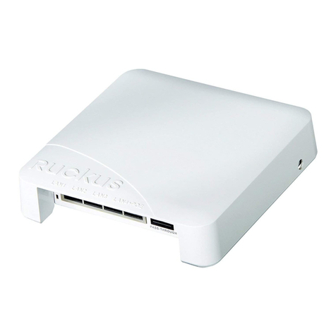
The ZoneFlex 7055 can be mounted to a variety of com-
monly used electrical outlet box formats, including US-
style outlet boxes conforming to NEMA-WD6, and EU-
style outlet boxes conforming to BS 4662.
• Remove the outlet box cover from the outlet box,
retaining the original box cover screws.
• Align the mounting bracket with the outlet box so
that the screw holes line up (the bracket provides
multiple holes for different outlet box designs), and
pull the Ethernet cable through the center of the
mounting bracket.
• Affix the mounting bracket to the outlet box using
the original outlet box cover screws. If the original
outlet box screw heads extend over 2mm from the
bracket, then use the enclosed low profile mounting
screws instead.
• Run the required cables through the electrical outlet
box allowing sufficient slack for the cables to reach
the not yet installed ZoneFlex 7055.
2Connect the cables.
• Connect an Ethernet cable providing PoE power and
network connectivity to the PoE In LAN / Uplink port
using either a standard RJ45 connector or the 110
punch-down block. Do not connect both. (See
ZoneFlex Indoor Access Point User Guide for ZF 7055
110 punch-down block wiring details).
• If PoE power is not available, the AP can be powered
using an optional DC power adapter (Ruckus part
#902-0170-XX10, sold separately)
• If required, connect the cable providing support for
pass-through devices to the Pass Through port.
3Mount the AP to the bracket.
• Snap the AP onto the mounting bracket by hooking
the two locking tabs on the bottom of the bracket
into the slots on the bottom of the AP. Then push the
top of the AP in toward the wall until it snaps in
place.
• Use the two Torx bracket screws provided to secure
the AP to the mounting bracket using a T10 Torx
screwdriver.
You have completed the physical installation.
Congratulations! Your wireless network is active and ready
for use.
FOR MORE INFORMATION
Refer to the ZoneFlex Indoor Access Point User Guide for
more detailed configuration and management information.
IMPORTANT: The AP and all interconnected equipment
must be installed indoors within the same building, includ-
ing the PoE powered network connection as described by
Environment A of the 802.3af standard.
IMPORTANT: Ensure that you use a Cat5e or better Ether-
net cable to supply PoE power and LAN connectivity run-
ning to the outlet box where the AP will be installed.
NOTE:
The ZoneFlex 7055 comes with a bracket for a single 1-
gang electrical outlet box. For adjacent outlet boxes, use
the optional Ruckus Wireless ZF7055 adjacent wall bracket
kit (part number 902-0111-000).
Rear view
PoE In Punch-down
block
LAN/Uplink
110
Pass Through
port
NOTE:
The status LEDs are intentionally not visible once the 7055
is mounted. Complete any verification or troubleshooting
that requires visibility of the LEDs before mounting.


