manuals.online logo
Brands
  1. Home
  2. •
  3. Brands
  4. •
  5. Ruckus Wireless
  6. •
  7. TV Mount
  8. •
  9. Ruckus Wireless T610 User manual

Ruckus Wireless T610 User manual

Copyright © 2017 Ruckus Wireless, Inc.
Published March 2017, Part Number 800-71404-001 Rev C Page 1 of 2
T610/T610s Mounting Bracket
Accessory Kit
Quick Setup Guide
This Quick Setup Guide provides step-by-step instructions on
how to field-install the Ruckus Wireless T610 access point (AP)
using the T610/T610s Mounting Bracket Accessory Kit (part
number 902-0125-0000).
The T610/T610s Mounting Bracket Accessory Kit includes two
different length Linkage Brackets, one for T610 (omni antenna
version) and one for T610s (sector antenna). If you are installing
a T610, use the longer linkage bracket (175 mm). If you are
installing a T610s, use the shorter (100 mm) linkage bracket.
For detailed information on planning the installation, performing
a site survey, and operating the AP, refer to the ZoneFlex
Outdoor Access Point User Guide, available at https://
support.ruckuswireless.com.
PACKAGE CONTENTS
A complete T610/T610s Mounting Bracket Accessory Kit
includes all of the items listed below:
• Mounting Bracket Hardware Kit (includes the following):
• Bolt, M8 x 1.25, 50 mm long, SS (2)
• Washer, Spring Lock, SS, DIN 127B, M8 (2)
• Washer, Flat, SS, DIN 125A, M8 (2)
• Clamp, Pipe, 1.5 in. to 2.5 in., +/-0.1 in. ID., SUS304 SST(4)
• Washer, Serrated External Tooth, Lock, M8, SST (2)
• Washer, .250, Split Lock, 18-8 SS (8)
• Washer, .250, Flat, 8-18 SS (8)
• Bolt, .250-28 x .50"L, Hex Head, SS (8)
• U Joint Bracket, Aluminum, 3mm thick
• Wall Mount Bracket, Aluminum, 3mm thick
• AP Bracket, Aluminum, 3mm thick
• 2 Linkage Brackets (100 mm, 175 mm length):
• For T610, use the 175 mm bracket;
• For T610s, use the 100 mm bracket
• Safety Cable Kit
•ThisQuick Setup Guide
REQUIRED HARDWARE AND TOOLS
• 1/2” (13mm) flat-blade screwdriver or equivalent
• No. 2 Phillips screwdriver
• Torque wrench or torque screwdriver with sockets
• Pipe or pole --OR-- a sturdy flat surface
• Electric drill with drill bits and customer-supplied wall anchors,
flat washers, and hex nuts for flat-surface mount
•Ruler
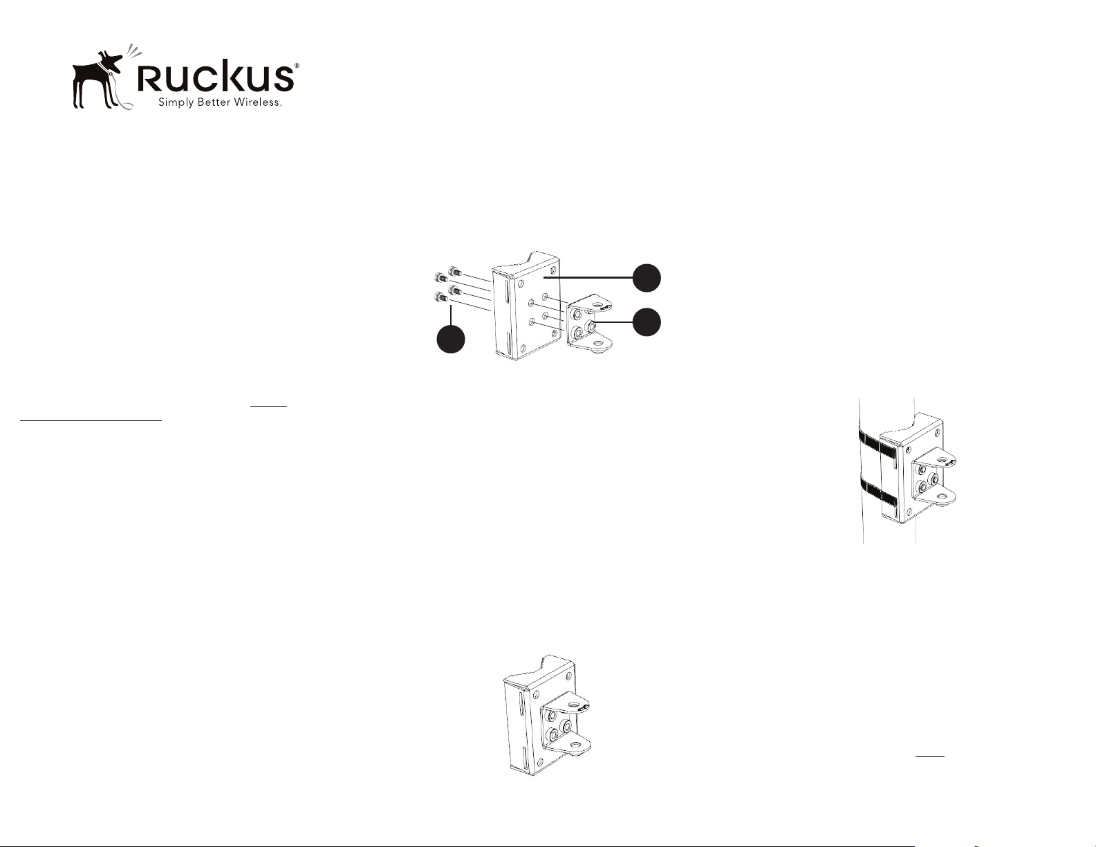
STEP 1: ATTACH THE U-JOINT BRACKET TO THE
MOUNTING BRACKET
1Position the U-joint bracket on the mounting bracket.
Figure 1: U-joint bracket attached horizontally to the mounting bracket
NOTE: Mount the U-joint bracket in any direction on the mounting
bracket, preferably to allow AP azimuth adjustments. Then the AP
bracket allows AP elevation adjustments.
2Use four 1/4-28 bolt and washer sets (A) to mount the U-joint
bracket (B) to the mounting bracket (C). Tighten the bolts to 9.5
N.m (7 ft-lbs).
3Continue with Step 2a: Attach the Mounting Bracket to a Flat
Surface or Step 2b: Attach the Mounting Bracket to a Metal
Pole.
STEP 2A: ATTACH THE MOUNTING BRACKET TO A
FLAT SURFACE
1Place the mounting bracket at the location on the flat surface
where you want to mount the AP. Use the holes on the mounting
bracket as a template to mark the locations of the mounting
holes.
Figure 2: Mounting bracket flat surface holes
2Remove the mounting bracket from the flat surface.
3Drill holes required for the mounting hardware.
NOTE: The hardware required for mounting to a wall is not
included in the mounting kit.
4Attach the mounting bracket to the flat surface using the
mounting hardware.
5Using the mounting hardware instructions, tighten the hardware to
secure the mounting bracket.
6Continue with Step 3: Mount the Linkage Bracket to the U-
Joint Bracket.
STEP 2B: ATTACH THE MOUNTING BRACKET TO A
METAL POLE
1Insert the open end of one steel clamp into the upper two slots on
the mounting bracket.
2Take the other steel clamp and insert it into the lower two slots on
the mounting bracket.
NOTE: The clamps can be daisy-chained together to accommodate
larger poles.
3Use the clamps to attach the mounting bracket to the pole.
Tighten the clamps to 3 N.m or 27 in-lbs, or per manufacturer’s
specifications.
Figure 3: Attaching the mounting bracket to a vertical pole
4Continue with Step 3: Mount the Linkage Bracket to the U-
Joint Bracket.
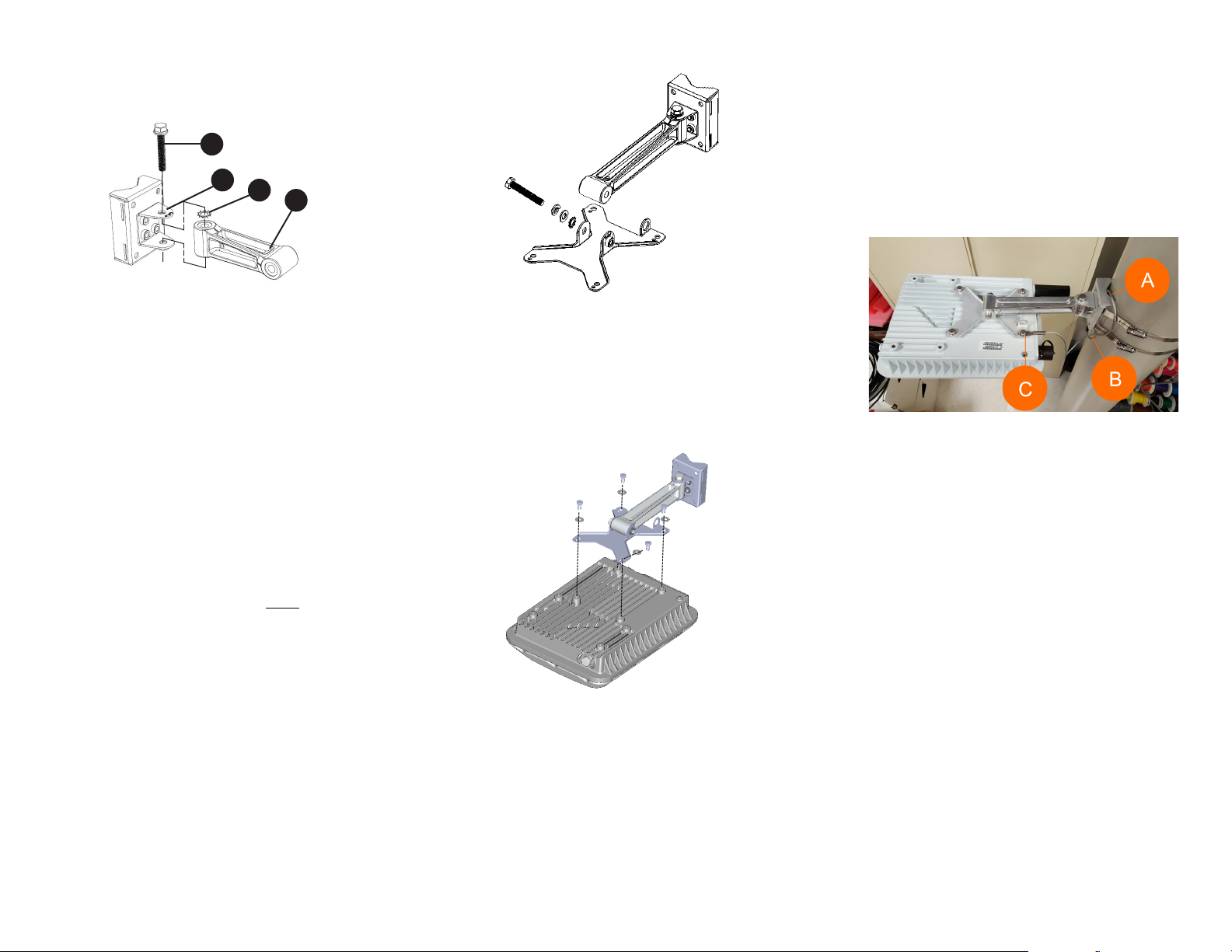
STEP 3: MOUNT THE LINKAGE BRACKET TO THE U-
JOINT BRACKET
NOTE: If you are mounting a T610 (omni), use the longer (175
mm) linkage bracket. If you are mounting a T610s, use the shorter
(100 mm) linkage bracket.
The linkage bracket attaches to the U-joint bracket using an M8
bolt and washer set. The linkage bracket is symmetrical, and
either end can be attached to the U-joint bracket.
NOTE: Make sure that linkage bracket is installed with its serrated
external-tooth lock washer on the inside of the U-joint bracket
flanges. This ensures that the azimuth adjustment does not
change.
C
B
A
Copyright © 2017 Ruckus Wireless, Inc.
Published March 2017, Part Number 800-71404-001 Rev C Page 2 of 2
1Loosely assemble the linkage bracket (A), the U-joint bracket (C),
one serrated external-tooth lock washer (B), and one M8 bolt
and washer set (D).
Figure 4: Attaching the linkage bracket to the U-joint bracket
2Set the azimuth required by the AP.
3Tighten the M8 bolt to 13.6 N-m (10 ft-lbs).
4Continue with Step 4: Attach the AP bracket to the linkage
bracket.
STEP 4: ATTACH THE AP BRACKET TO THE LINKAGE
BRACKET
NOTE: If you are mounting a T610 (omni), use the longer (175
mm) linkage bracket. If you are mounting a T610s, use the shorter
(100 mm) linkage bracket.
Attach the AP bracket to the linkage bracket using the included
bolt, nut, lock washer, flat washer, serrated external-tooth
washer shown in Figure 5.
The AP bracket attaches to the linkage bracket using an M8
bolt and washer set. The linkage bracket is symmetrical, and
either end can be attached to the AP bracket.
NOTE: Make sure that the linkage bracket is installed with its
serrated external-tooth lock washer on the inside of the AP
bracket flanges. This ensures that the elevation adjustment does
not change.
1As described in Step 3: Mount the Linkage Bracket to the U-
Joint Bracket, loosely assemble the AP bracket (shown in
Figure 6), the linkage bracket (A in Figure 4), the second
serrated external-tooth lock washer (B in Figure 4), and the
second M8 bolt and washer set (D in Figure 4).
Figure 5: Attach the linkage bracket to the AP bracket
STEP 5: ATTACH THE AP BRACKET TO THE ACCESS
POINT
1Place the AP bracket onto the back side of the AP so that the four
larger screw holes on the bracket align with the four screw holes
on the AP. Make sure that the end of the AP bracket with the
hoisting loop is on the same side as the AP PoE IN port.
Figure 6: Attaching the AP bracket to the AP
2Use four 0.5-inch x 0.250-28 hex bolts with split lock and flat
washer sets to mount the AP bracket to the AP. Tighten the bolts
to 2.5-3.0 N.m or 22-27 in-lbs.
CAUTION: Make sure that the screws are no longer than 0.5 inch.
If a screw is longer than 0.5 inch, it can damage the AP chassis.
3If required, suspend the AP by attaching a carabiner to the
hoisting loop on the AP bracket.
NOTE: This kit may include extra screws, nuts and washers. You
may use the extras wherever required.
4Continue with Step 6: Set the Elevation and Tighten Elevation
Bolt.
STEP 6: SET THE ELEVATION AND TIGHTEN ELEVA-
TION BOLT
1Set the elevation required by the AP.
2Tighten the M8 bolt to 13.6 N-m (10 ft-lbs).
STEP 7: INSTALL THE SECURITY CABLE
1Thread the security cable through the mounting bracket (A) and
through the eye on the cable itself (B), as shown in Figure 7.
2Attach the safety cable to the AP (C) in Figure 7.
Figure 7: Attaching the security cable
Congratulations! You have mounted your T610/T610s access
point.
A
C
B
D

This manual suits for next models

1

Popular TV Mount manuals by other brands

Novus NVB-5300JB user manual

Novus

Novus NVB-5300JB user manual

Hama 00118611 operating instructions

Hama

Hama 00118611 operating instructions

ACT AC8336 Quick install

ACT

ACT AC8336 Quick install

Ergotron StyleView SV31 user guide

Ergotron

Ergotron StyleView SV31 user guide

Sanus FTVS1 instruction manual

Sanus

Sanus FTVS1 instruction manual

Mounting Dream MD2377-02 Installation instruction

Mounting Dream

Mounting Dream MD2377-02 Installation instruction

ERARD EXO400OLEDTW3 manual

ERARD

ERARD EXO400OLEDTW3 manual

PEERLESS PLP PION50 Installation and assembly

PEERLESS

PEERLESS PLP PION50 Installation and assembly

Wisenet SBP-137WM quick start guide

Wisenet

Wisenet SBP-137WM quick start guide

peerless-AV LCZ-4F430B Installation and assembly

peerless-AV

peerless-AV LCZ-4F430B Installation and assembly

PEERLESS Smartmount ST630P  and assembly Installation and assembly manual

PEERLESS

PEERLESS Smartmount ST630P and assembly Installation and assembly manual

SMS Func Flatscreen CHVSTD2 Installation and adjustment manual

SMS

SMS Func Flatscreen CHVSTD2 Installation and adjustment manual

Sanus VMD2 installation instructions

Sanus

Sanus VMD2 installation instructions

Sanus Systems VisionMount VMPL2 manual 

Sanus Systems

Sanus Systems VisionMount VMPL2 manual 

Vivo MOUNT-VW11 instruction manual

Vivo

Vivo MOUNT-VW11 instruction manual

Vivo MOUNT-VW080P instruction manual

Vivo

Vivo MOUNT-VW080P instruction manual

Crimson CMR-301 user guide

Crimson

Crimson CMR-301 user guide

Suptek MD6821 installation manual

Suptek

Suptek MD6821 installation manual

manuals.online logo
manuals.online logoBrands
  • About & Mission
  • Contact us
  • Privacy Policy
  • Terms and Conditions

Copyright 2025 Manuals.Online. All Rights Reserved.