RUD VWBG-V 0.3 M8 User manual

For further information on our complete range of products and services please visit our website at www.rud.com.au
VWBG-V LOAD RING
For further information on our complete range of products and services please visit our website at www.rud.com.au
Complies with the machinery directives 2006/42/EC
NB: Please ensure that the safety instructions have been fully read and understood before initial use of the
VWBG-V bolt-on
lifting point
.Failure to do so may resultin seriousinjuries and/or material damage and eliminates manufacturers warranty.
User Instructions - Part 1
Safety instructions
This safety instruction/declaration of the manufacturer must be
ATTENTION: Please inspect all components prior to use.
Damaged, incorrect assembly or improper use may result
in serious injuries and/or material damage.
EC-Declaration of the manufacturer
According to the Machinery Directive 2006/42/EC, annex II B
and amendments.
We hereby declare that the design and construction of the
equipment detailed within this document, adheres to the
appropriate level of health and safety of the corresponding EC
regulation.
the equipment not adhered to within these user instructions
waivers this declaration invalid.
The equipment must be regularly tested and inspected as per
BGR 500. Failure to carry out the recommended maintenance
and testing waivers this declaration invalid.
Designation of the equipment:
Type: Hoist Ring for Bolting Vario VWBG-V
Manufacturer’s mark:
Drawings (iges, dxf and step), product information and other
support material can be downloaded from www.rud.com.au.
EC-Declaration of conformity
According to the EC-Machinery Directive 2006/42/EC, annex II A and amendments
Manufacturer:
RUD Ketten
Rieger & Dietz GmbH u. Co. KG
Friedensinsel
73432 Aalen
We hereby declare that the equipment sold by us because of its design and construction,
as mentioned below, corresponds to the appropriate, basic requirements of safety and
health of the corresponding EC-Machinery Directive 2006/42/EC as well as to the below
mentioned harmonized and national norms as well as technical specifications.
In case of any modification of the equipment, not being agreed upon with us, this declara-
tion becomes invalid.
Product name:
Load ring
_____________________________________________
VWBG-V / VWBG
_____________________________________________
The following harmonized norms were applied:
EN 12100 :2011-03 EN 1677-1 :2009-03
__________________________________
EN 1677-4 :2009-03
__________________________________
__________________________________
__________________________________
__________________________________
The following national norms and technical specifications were applied:
BGR 500, KAP2.8 :2008-04
__________________________________
__________________________________
__________________________________
__________________________________
__________________________________
Authorized person for the configuration of the declaration documents:
Reinhard Smetz, RUD Ketten, 73432 Aalen
Aalen,den 27.06.2014
Dr.-Ing. Arne Kriegsmann,(Prokurist/QMB)
_____________________________________________
Name, function and signature of the responsible person

The German testing authority BG, recommends the
following minimum for the bolt lengths:
1.0 x M in steel (minimum quality S235JR [1.0037])
≈AS3678 GR250.
1.25 x M (thread diameter) in cast iron (e.g. GG 25)
2 x M (thread diameter) in aluminium
2.5 x M (thread diameter) in light alloys of low strength
(M = thread size/diameter, e.g. M20)
• When lifting light metals, nonferrous metals and gray cast
iron the thread has to be chosen in such a way that the
WLL of the thread corresponds to the requirements of the
base material.
• The min. quality of the hexagon bolt of the VWBG-V must
be class 10.9 according to EN 24014 (DIN 931) with correct
nominal diameter.
• RUD supplies the Vario length complete with a washer and
crack-detected nut corresponding to DIN EN ISO 7042
(DIN 980) or will be supplied with a crack inspected collar
nut acc. to DIN 6331 or 2 x crack inspected hex nuts Class
8 AS1112.1 with washer.
• The position of the lifting points must be carried out in such
be avoided.
• For single leg lifts, the lifting point should be vertically
above the centre of gravity of the load.
• For two leg lifts, the lifting points must be equidistant to/
or above the centre of gravity of the load.
• For three and four leg lifts, the lifting points should be
arranged symmetrical around the centre of the gravity, in
the same plane if possible.
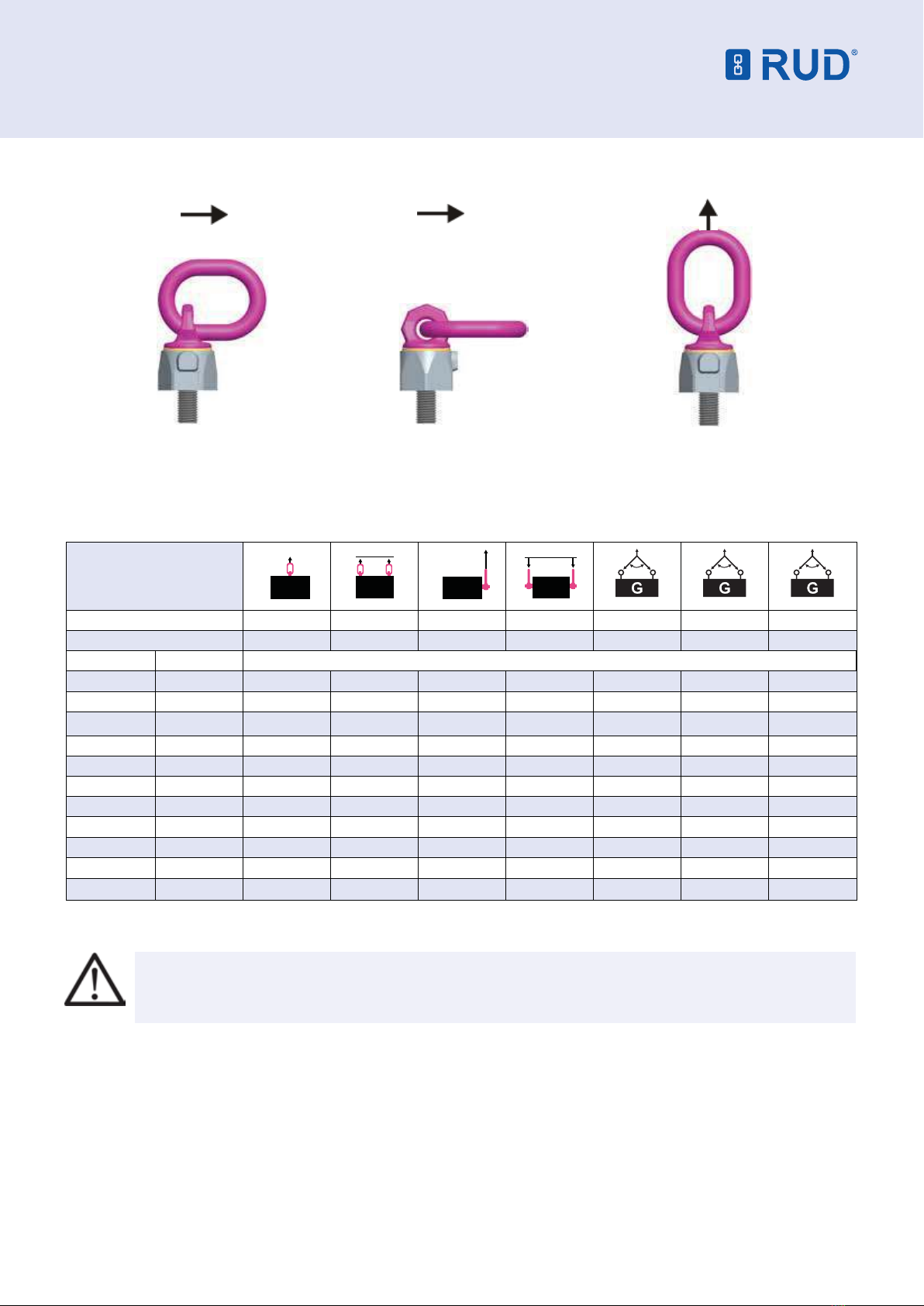
Load Symmetry: The working load limit of individual RUD
lifting points are calculated using the following formula and
are based on symmetrical loading:
NOTE: For WLL Calculations
• ß angle is taken from the vertical plane.
• Included angle is the angle between the sling legs.
Number of load bearing legs is as follows:
Symetrical Unsymetrical
2/3/4 leg 2 1
Load bearing legs (compare also with table 1)
• When lifting points are used in a multileg assembly, care
should be taken to calculate the WLL (Working Load Limit)
due to the deration caused by forces acting in multiple
directions. The reduction in WLL (Working Load Limit)
for multileg assemblies should be checked with relevant
Standards e.g. AS 3775.2:2014 Chain slings for lifting
purposes - Grade T(80) and V(100) - Care and use.
• The lifting points should be mounted in such a way that
they may easily be accessed for inspection and assembly/
disassembly of the sling.
VWBG-V LOAD RING
User Instructions - Part 2
1. Safety Instructions
ATTENTION: Please inspect all lifting points
prior to use. Damage, incorrect assembly or
improper use may result in serious injuries
and/or material damage.
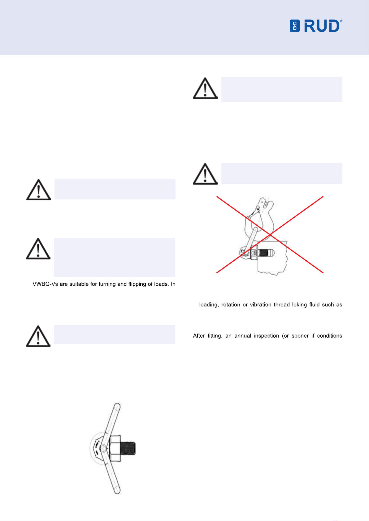
• Not suitable for permanent turning operations under load.
Lifting point cannot be turned to 90° from the bolt-on
direction under full load.
• The ball bearing must not be disassembled.
• The load ring must not be free to articulate.
• RUD VWBG-V lifting points must only be used by instructed
and competent persons considering BGR 500 / DGUV 100-
statutory regulations.
2. Intended use of VWBG-V
RUD VWBG-V lifting points must only be used for the assembly
at the load or at lifting means.
They are intended to be bolted into the payload and can be
turned under load, but not under full load, especially not in the
90° direction. Not suitable for permanent turning operations
under load.
RUD VWBG-V lifting points can also be used as lashing points
to attach lashing means.
If the lifting points are used exclusively for lashing the value
of the WLL (working load limit) can be doubled. LC (lashing
capacity) = 2 x WLL.
RUD VWGB-V lifting points must only be used in the hereby
described operation purpose.
Before installing and every use, visually inspect RUD lifting
points, with particular attention to any evidence of corrosion,
wear and weld cracks and deformations. Please ensure
compatibility of bolt thread and tapped hole.
3. Assembly and Instruction Manual
3.1 General Information
• Temperature range:
Usage at higher temperatures is not recommended due to
necessary, the working load limit (WLL) of the VWBG-V
must be reduced as follows:
-40°C up to 100°C no reduction
100°C up to 200°C minus 15 %
200°C up to 250°C minus 20 %
250°C up to 350°C minus 25 %
Temperatures exceeding 350°C are prohibited!
Please pay attention when using DIN EN 7042 (DIN 980)
nuts the max. operation temperature of 150°C (acc. to DIN
EN ISO 2320).
• RUD VWBG-V lifting points must not be used with
aggressive chemicals such as acids, alkaline solutions and
their vapours.
3.2 Hints for the assembly
• The material construction to which the lifting point will be
attached should be of adequate strength to withstand forces
during lifting without deformation.
WLL = required of lifting point/individual leg (kg)
G = load weight (kg)
n = number of load bearing legs
ß = angle of inclination of the individual leg
WLL = G
n x cos ß

Pic. 1: Pivoting area
ca. 230°
• A plane bolting surface must be guaranteed to ensure
correct mating of the lift compoment. The thread must be
carried out acc. to DIN 76 (countersink max. 1.05xd).
• Tapped holes must be machined deep enough so that
the bearing surface of the lifting point will be supported.
Machine through holes up to DIN EN 20273-middle.
• For single use just tighten with spanner. For long term
application and when turning loads the VWBG-V should be
tightened to torque according to relevant table (+/- 10%).
In case of turning movements (continuous operation) the
recommended torques have to be checked regulary.
• The type VWBG-V can be supplied with different thread
lengths (see Fvario in table 2), and the metric versions with
washer and crack detected nut.
ATTENTION: Check the correct assembly
(see chapter 4, Inspection Criteria).
3.3 User Instructions
• Check frequently and before each initial operation the
whole lifting mean for corrosion, wear, deformation etc.
(see chapter 4, Inspection criteria).
ATTENTION: Incorrectly assembled or
damaged lifting points, as well as improper
use can lead to injuries to persons and
plant damage. Please inspect all lifting
points before each use.
•
doing so, all positions of the ring can occur. The stated
WLL at the lifting point is given for the most inappropriate
possible case of operation (see picture 5 - part X). When
ring has been adjusted manually (see picture Y) the higher
(WLL) values from table 3 can be used.
ATTENTION: Pay attention during the usage
that the load type will not be changed.
If the VWBG-V is to be loaded only perpendicular (in
axial direction of the thread, see picture 3 - part Z) the
corresponding WLL values from table 3 (inclination angle
0°) can be used.
• The ring of the manually adjusted VWBG-V can be pivoted
by approx. 230° (see picture 1).
VWBG-V LOAD RING
User Instructions - Part 2
Pic. 2: Forbidden contact or support at/or with edge
ATTENTION: The lifting ring must rotate
and pivot without interference during lifting
(see picture 2).
• When lifting means (sling chains) are hinged or unhinged,
no pinching, shearing or joint spots must occur during the
handling. Avoid damage of lifting means resulting from
sharp edges.
• Distance yourself from the direct danger zone.
• Always watch the load during the lift.
• Avoid sudden or shock loading.
ATTENTION: Loading or vibration can lead
to unintentional loosening.
• To prevent unintentional dismounting through shock
Loctite (depending on the application, please refer to the
manufacturer‘s instruction) should be used to secure the bolt.
3.4 Hints for regular inspection
dictate) should be carried out by a competent person
examining for continued suitability. Also inspect after damage
and special occurance.

VWBG-V LOAD RING
User Instructions - Part 2
4 Inspection criteria
Observe and control the following points before each initial
operation at regular time intervals, after the assembly and
after special incidents:
• Correct bolt- and nut size plus thread engagement.
• Inspection of bolting torque.
• The bearing surface of the VWBG-V must be plane.
• Completeness of the lifting point.
• Complete readable WLL markings and manufacturer sign.
• Deformation at load bearing components e.g. base body,
load ring and threaded bolt.
• Mechanical damage, like notches, especially in areas
where tensile stress occurs.
• Locking screw at the side must be tightened.
• Reduction of cross-section due to wear >10 % or when the
wear marks have been reached in the main load bearing
directions.
• Cracks or any other damage.
• Function and damage of bolt threads and nuts.
• Smooth rotation between upper and base part of the
VWBG-V must be guaranteed.
• The maximum gap “S” between upper and base part must
not be exceeded:
VWBG-V 0.3 - 0.45: max. 1.2 mm
VWBG-V 0.6 - 2.0: max. 1.5 mm
VWBG-V 3.5 - 5.0: max. 3.0 mm
5 Hints for the Repairing
Repair work must only be carried out by a competent person
at RUD or by a RUD trained and authorised service station,
which has obtained the necessary knowledge and skills.
RUD-VWBG-V’s are designed for a dynamical loading
of 20.000 load cycles at nominal working load. The BG
recommends: At a high dynamic loading with high numbers
of load cycles (continious work) the bearing stress acc. to
FEM group 1Bm (M3 acc. to DIN 818-7) must be reduced.
Example to investigate the required thread length F vario:
Plate thickness 50 mm, through hole for M 20 bolt, height of
nut 20 mm, thickness of the washer 3mm, plus bolt projection
5 mm (2x pitch).
Order length: VWBG-V-2.0 M 20 x 78.
Bearing wear groove
S
Pic. 3: Distance between upper and
base part plus bearing wear groove

Method of lifting
Number of Legs 1 2 1 2 2 / 3 / 4 2 / 3 / 4 2 / 3 / 4
Load Direction 0° 0° 90 ° 90 ° 60° 90° 120°
Type Thread
WWBG-V 0.3 M8 / 5/16’’ 0.6 1.2 0.3 (0.4) 0.6 (0.8) 0.52 (0.69) 0.42 (0.56) 0.3 (0.4)
VWBG-V 0.45 M10 / 3/8’’ 0.9 1.8 0.45 (0.6) 0.9 (1.2) 0.78 (1.0) 0.63 (0.85) 0.4 (0.6)
VWBG-V 0,6 M12 / 1/2’’ 1.2 2.4 0.6 (0.75) 1.2 (1.5) 1.0 (1.3) 0.85 (1.1) 0.6 (0.7)
VWBG-V 1.0 M14 2.0 4.0 1.0 (1.25) 2.0 (2.5) 1.73 (2.2) 1.4 (1.8) 1.0 (1.25)
VWBG-V 1.3 M16 / 5/8’’ 2.6 5.2 1.3 (1.5) 2.6 (3.0) 2.2 (2.6) 1.8 (2.1) 1.3 (1.5)
VWBG-V 1.8 M18 3.6 7.2 1.8 (2.0) 3.6 (4.0) 3.1 (3.5) 2.5 (2.8) 1.8 (2.0)
VWBG-V 2.0 M20 / 3/4’’ 4.0 8.0 2.0 (2.5) 4.0 (5.0) 3.5 (4.3) 2.8 (3.5) 2.0 (2.5)
VWBG-V 2.0 M22 4.0 8.0 2.0 (2.5) 4.0 (5.0) 3.5 (4.3) 2.8 (3.5) 2.0 (2.5)
VWBG-V 3.5 M24 / 1’’ 7.0 14.0 3.5 (4.0) 7.0 (8.0) 6.1 (6.9) 4.9 (5.6) 3.5 (4.0)
VWBG-V 5.0 M27 7.0 14.0 3.5 (4.0) 7.0 (8.0) 6.1 (6.9) 4.9 (5.6) 3.5 (4.0)
VWBG-V 5.0 M30 / 11/4’’ 10.0 20.0 5.0 (6.0) 10.0 (12.0) 8.7 (10.4) 7.1 (8.5) 5.0 (6.0)
Table 1: WLL-overview VWBG-V
Vertical loading
(WLL acc. to chart)
Z
Nominal WLL
(worst case scenario)
* X
Manual adjustment
(higher values in brackets possible
depending on usage)
Y
Pic. 4: Loading directions
G
GG
A
G
A
User Instructions - Part 3
NOTE: The VWBG-V is designed to rotate and turn the load. Therefore the lifting point can engage in any position.
The WLL is embosed for the worst case situation in which the load direction may occur (see picture X).
The ring can be manually adjusted to the direction of pull (see picture Y). Then the values in the brackets can be used.
VWBG-V LOAD RING

VWBG-V LOAD RING
12 Commerce Place, Larapinta QLD 4110
p 07 3809 1300 f 07 3809 1301
107 Broadway, Bassendean WA 6054
p 08 6278 1788 f 08 6278 4788
[email protected] www.rud.com.au
VWBG-V LOAD RING
Pic. 5: Dimensioning VWBG-V (standard)
dim. without
thread
= F max
max. material
thickness
Pic. 6: Dimensioning VWBG-V (vario)
User Instructions - Part 3
Type WLL [t] A
[mm]
B
[mm]
C
[mm]
D
[mm]
Fstand
[mm]
Fmax
[mm]
G
[mm]
K
[mm]
M
[mm]
T
[mm]
X weight
[kg/
pc.]
Bolting
Torque
[Nm]
Ref.-No.
Stand.
Ref.-No.
Vario
with
washer
and nut
VWBG-V 0.3 M8 0.3 (0.4) 8 31 29 30 13 102 36 28 8 76 18 0.25 10 7103720 8600330
VWBG-V 0.45 M10 0.45 (0.6) 8 31 29 36 17 122 38 30 10 78 19 0.3 10 7103715 8600331
VWBG-V 0.6 M12 0.6 (0.75) 10 49 35 42 21 140 47 36 12 107 19 0.4 10 7100180 8600332
VWBG-V 1.0 M14 1.0 (1.25) 13 46 38 48 21 65 56 41 14 113 - 0.6 25 - 8600337
VWBG-V 1.3 M16 1.3 (1.5) 13 46 38 48 25 180 56 41 16 113 28 0.6 30 7100430 8600333
VWBG-V 1.8 M18 1.8 (2.0) 13 54 35 62 27 83 67 55 18 137 - 1.1 50 - 8600338
VWBG-V 2.0 M20 2.0 (2.5) 13 54 35 62 33 223 67 55 20 137 30 1.4 70 7100800 8600334
VWBG-V 2.0 M22 2.0 (2.5) 13 54 35 62 33 94 64 55 22 137 - 1.5 120 - 8600334
VWBG-V 3.5 M24 3.5 (4.0) 18 66 40 81 40 255 88 70 24 173 25 2.6 150 7100640 8600335
VWBG-V 3.5 M27 3.5 (4.0) 18 66 40 81 40 92 88 70 27 173 - 2.9 200 - 8600335
VWBG-V 5.0 M30 5.0 (6.0) 22 90 50 99 50 330 106 85 30 221 32 5.5 225 7100650 8600336
Table 2: Dimensioning (metric)
Type WLL [t] A
[mm]
B
[mm]
C
[mm]
D
[mm]
F
[mm]
G
[mm]
K
[mm]
M
[mm]
T
[mm]
weight
[kg/pc]
Bolting-
torque
[Nm]
Ref.-No.
Stand.
VWBG-V 0.3 - 5/16’’ - 18 UNC 0.3 (0.4) 8 31 29 30 13 36 28 5/16’’ 76 0.25 10 7991090
VWBG-V 0.45 - 3/8’’ - 16 UNC 0.45 (0.6) 8 31 29 36 17 38 30 3/8’’ 78 0.3 10 7991091
VWBG-V 0.6 - 1/2’’ - 13 UNC 0.6 (0.7) 10 49 35 42 21 47 36 1/2’’ 107 0.4 10 7991092
VWBG-V 1.3 - 5/8’’ - 11 UNC 1.3 (1.5) 13 46 38 48 29 56 41 5/8’’ 114 0.6 30 7991093
VWBG-V 2.0 - 3/4’’ - 10 UNC 2.0 (2.5) 13 54 35 62 29 67 55 3/4’’ 137 1.4 70 7991094
VWBG-V 3.5 - 1’’ - 8 UNC 3.5 (4.0) 18 66 40 81 40 88 70 1’’ 173 2.6 150 7991095
VWBG-V 5.0 - 11/4’’ - 7 UNC 5.0 (6.0) 22 90 50 99 48 106 85 11/4’’ 221 5.5 225 7991096
Table 3: Dimensioning VWBG-V*
This manual suits for next models
10
Other RUD Construction Equipment manuals
Popular Construction Equipment manuals by other brands

S.D.P.
S.D.P. EZ Hauler 3000 Training & Procedure Manual

Inder
Inder Hydraulic P-281 User instruction manual

MULTIQUIP
MULTIQUIP WM90SE Operation manual

Global Manufacturing
Global Manufacturing GWE Series operating instructions

Scheppach
Scheppach HP1200S Translation of original instruction manual

KRAUSE
KRAUSE MONTO ProTec 1000 Assembly instructions and user's manual