Table of Figures
5
RuggedCom®RuggedSwitch® RS940G Installation Guide rev101
Table of Figures
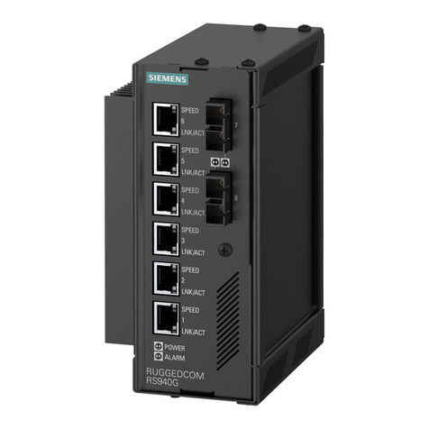
Figure 1 - RS940G Front Panel Description .............................................................................................. 7
Figure 2 - RS940G Bottom Panel Description............................................................................................ 8
Figure 3 - RS940G DIN Rail Mounting...................................................................................................... 9
Figure 4 - RS940G Power Supply Inputs ................................................................................................. 10
Figure 5 - DC Power supply wiring and grounding diagram................................................................. 11
Figure 6 - Dielectric Strength Testing....................................................................................................... 12
Figure 7 - RS940G Failsafe Output Relay................................................................................................ 13
Figure 8 - RS232 DCE pin-out................................................................................................................... 14
Figure 9: 1000LX SFP (mini-GBIC) Module and LC connector.......................................................... 16
Figure 10: 1000LX SC connector............................................................................................................. 16
Figure 11: 1000LX LC connector............................................................................................................. 16
Figure 12: SFP Bail Latch location.......................................................................................................... 18
Figure 13: SFP Removal........................................................................................................................... 18
Figure 14: Copper Port LED Description................................................................................................ 18
Figure 15: Fiber Port LED Description.................................................................................................... 18
Figure 16 - Mechanical Specifications...................................................................................................... 23
Table of Tables
Table 1 - Status LEDs................................................................................................................................... 7
Table 2: Cabling categories and 1000BaseTx compliance defined........................................................ 15
Table 3 – RJ45 Ethernet port 9 LED description.................................................................................... 19
Table 4 - Operating Environment............................................................................................................. 20
Table 5 - Power Supply Specifications...................................................................................................... 20
Table 6 - Failsafe Relay Specifications...................................................................................................... 20
Table 7- Networking Standards Supported ............................................................................................. 21
Table 8- Twisted-Pair Port Specifications................................................................................................ 21
Table 9 - Mechanical Specifications.......................................................................................................... 21
Table 10 - IEC 61850-3 Type Tests........................................................................................................... 23
Table 11 - IEEE 1613 Type Tests.............................................................................................................. 25
Table 12 - Environmental Type Tests....................................................................................................... 25
