Drive Roller RDR BL-2 Version 1.1 User installation, connection & Warranty Manual
User-Man-RDR BL-2 v.1.1 - Rev 30-03-17.docx pag. 2
wires section
0.2 mm²
A white wire is present in the cable with no customer use, to be kept
isolated. The input-output signals are PNP type and possible to be
directly connected to PLC.
•POWER SUPPLY: connect the BLUE (GND) and BROWN (24VDC)
bigger section wires to a 24VDC power supply, sufficient for all the
connected RDR running at a time, at the max transported load
absorbed current. If a PLC or outer signals are used, the 0V-GND of
RDR power supply and the one of PLC must be jumped together.
IMPORTANT: Verify that no high spikes over 40V are present on the
DC supply or on the signals, or in case put filters on disturb sources
(contactors, AC motors etc.), or use different power supplies, with
separate +24VDC. Avoid to connect RDR 0VDC to the AC ground, if
this is required please ensure that no eddy currents are present.
In case of very long 24VDC main supply line, verify on RDR a voltage
around to 24V (or in any case in between the admitted voltage
18-28V) on nearer and farer loaded RDRs from power supply.
In case adjust power supply voltage, increase wires section and/or
connect 24VDC supply as closed loop.
WARNING: in case a power supply is feeding many RDRs with
frequent contemporary start/stops or inclined conveyor, please use
a Motor Brake Controller system (Chopper). Example Cabur MBC2K
or Maxon Motor Shunt Regulator or Mi-Control mod. mcER-L40 o
L41, not included in the delivery, 1 each power supply (please ask
technical details to Rulmeca).
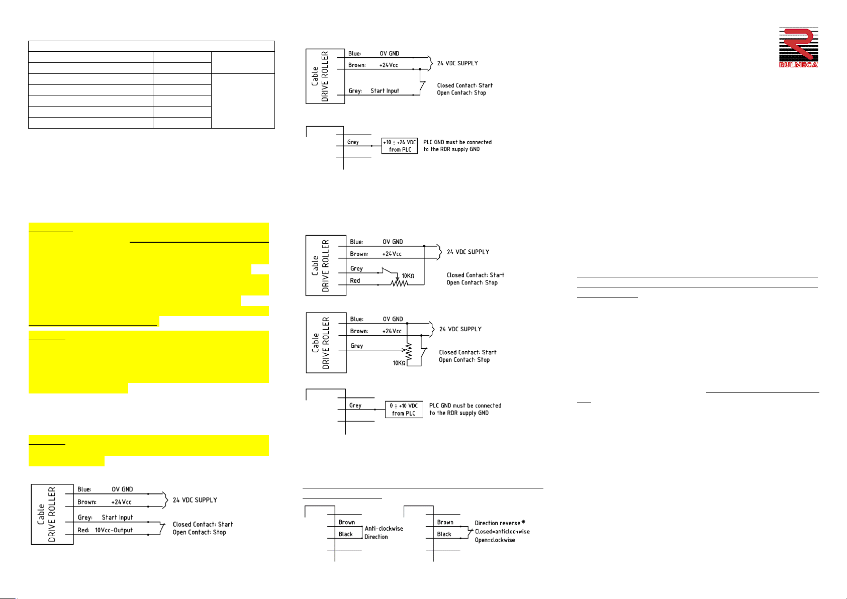
•START : after having connected the 24 VDC supply, to start the RDR
at max speed apply 10-24VDC to the GREY wire or jump the RED and
GREY leads.
WARNING: do not switch off the RDR by direct contacts on the main
24VDC supply, because the load inertia can cause RDR over-voltages
and electronics faults.
Start-stop by contact near the RDR (max 3 m)
Start-stop by remote contact
Start-stop by PLC
•SPEED VARIATION : apply a variable voltage 0÷10V or 24V, to GREY
wire: 2.3VDC standing; 2.3 ÷ 10 VDC min-max speed adjust;
10 ÷ 24 VDC all max speed.Use a 10KΩpotentiometer.
The RED wires, gives a 10VDC for the signal supply.
Speed adjustment by potentiometer near the RDR
Speed adjustment by remote potentiometer
Speed adjustment by PLC
•DIRECTION REVERSAL: the not connected BLACK wire voltage level is
low (0V) and the RDR is running in the default clockwise direction.
To invert the RDR rotation into anti-clockwise direction, give a +24V
to the BLACK wire. The rotation direction is seen from the cable side.
WARNING: The reverse signal must be given before the start signal,
with the standing RDR.
•TTL Signal: green wire. The internal TTL sensors give a
square wave 0–5V (TTL signal) with a resolution of 12
pulses per motor rotor revolution, at any speed.
•FAULT: in case the RDR is running at correct temperature and
current, the Fault signal output voltage on the YELLOW cable is
+24VDC. In case of over-temperature (>85°C) or over-current the
Fault signal output voltage is going down to GND-0V (alarm logic).
The fault signal output can provide max 20 mA.
Over-temperature fault: RDR BL-2 gets an inner temperature sensor.
When the motor temperature goes over 85°C, the RDR activates the
Fault signal output (YELLOW wire), by pulling it from +24V down to
0V. After 60 seconds, if the RDR is not manually switched off, the
inner drive provides to switch off the motor. The over-temperature
Fault signal automatically resets after the motor reaches a
temperature <75°C and the RDR resumes to work.
Over-current fault: the RDR BL-2 motor is protected against over-
current due to roller overloading or material block on the conveyor.
If the current goes over 3A, the inner drive reduces the current down
to 1.5A for 2 sec., then stops the motor. Then it is trying to restart
the roller 3 times. If still blocked, the fault signal output is activated
by pulling it from +24V down to 0V and the motor is switched off.
To reset the over-current Fault, the material block must be removed
and then the mains supply must be switched off and after few
seconds back on. The RDR restarts normally.
•SAFETY PROTECTION:the RDR Drive Roller is protected against
polarity inversion of the supply voltage, for a safe connection
avoiding burning risks.
WARRANTY
Rulmeca gives a 12 months warranty, starting from the delivery date, on
the RDR Drive Rollers and on the external Electronic boards (if any),
against material or production defects. According to this warranty, the
products returned to our factory site: Via Toscanini 1, 24011 Almè (BG),
Italy, or to our Rulmeca sister company sites and found defective, will be
repaired or replaced under warranty.
-As pure components, the present warranty doesn't cover the costs for
RDR disassembling-reassembling from the conveyor and for return
transports.
-This warranty is void in case of clear overloaded products, twisted cables,
incorrect assembly, wrong connection (not according to the present
diagrams and instructions), tampering, alteration, wrong cleaning with
aggressive procedures or products and intervention by people not
qualified by Rulmeca.
-The std. warranty is not covering the working wear of the shell, rubber or
coatings or other damages due to shocks or accidents.
-The warranty is not covering indirect damages or loss of production due
to product brake down (for critical applications keep proper spare parts,
suitable for fast replacement).
- This warranty is applying to the Rulmeca client and it is not transferable
to a third part.


