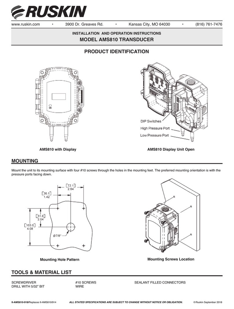
Ruskin AMS Series Owner's manual

)LJ6HWXS
6ZLWFKHVIRU
6WDQGDUG
5DQJH8QLWV
6HOHFW287387
6HOHFW5$1*(
,IXQLWLVRUGHUHGZLWKD&XVWRP5DQJH
WKHQWKHVZLWFKPXVWEHVHWWR5
&KRRVH',5(&7,21
%LGLUHFWLRQDOLVDSOXVPLQXVUDQJHVR
FKRRVLQJ´UDQJHLV´WR´%LGLUHFWLRQDO
DQG´WR´8QLGLUHFWLRQDO
&KRRVH81,76,QFKHV:&RU3$6&$/6
&KRRVH5(63216(7,0(
)DVW5HVSRQVH VHFRQG
6ORZ5HVSRQVH VHFRQGV
0RXQW7HUPLQDWHDQG$XWR=HURWKHXQLW
DVGHVFULEHGLQODWHUVHFWLRQV$WWDFK
WKHGHDGKHDGWXELQJWRWKHSRUWVGXULQJ
$XWR=HURLQJ
www.ruskin.com • 3900 Dr. Greaves Rd. • Kansas City, MO 64030 • (816) 761-7476
INS ALLA ION AND OPERA ION INS RUC IONS
AMS SERIES RANSDUCERS (AMS8100, AMS8100LR)
SWI CH SE UP - OU PU S, RANGES, UNI S/RESPONSE
ALL STATED SPECIFICATIONS ARE SUBJECT TO CHANGE WITHOUT NOTICE OR OBLIGATION. © Ruskin October 2019
II-AMS8100-1019/Replaces -AMS8100-619
Figure 1
Do not have power applied to unit when changing settings. After changing settings, apply power and Auto-Zero the unit in its
orientation of operation.
Ruskin’s AMS series are the most versatile pressure
transducers on the market with selectable
pressure ranges and selectable voltage or current
output to satisfy the most demanding air measure-
ment applications. Switch selectable fast or slow
response time provides the ability to smooth out
velocity pressure measurements that are the result
of less than ideal installation locations and turbulent
air flows.
The LCD display shows the actual velocity pressure
independent of the output pressure range selected.
This makes it extremely easy for the installing tech-
nician to know what pressure range to use for each
application. With the maximum air flow passing
through the air measurement station just look at the
displayed value and select the lowest range that
includes the pressure. t’s that easy! By selecting
the correct pressure range, the electrical output can
be scaled for the greatest measurement resolution
and corresponding air flow control.
At a glance troubleshooting can save hours of work.
The three LEDS on the face of the AMS series
low-pressure transducer, above the display, indi-
cate when the velocity pressure being measured is
“Out of Range Low” (or negative), “Out of Range
High” or operating as expected when the “ n
Range” LED is illuminated.
PRODUC IDEN IFICA ION
AMS Series Transducer with Display
1. Select OUTPUT
2. Select RANGE
f unit is ordered with a Custom Range,
then the switch must be set to R6.
3. Choose D RECT ON
Bidirectional is a plus/minus range so
choosing 5” range is -5” to +5” Bidirectional
and 0” to +5” Unidirectional
4. Choose UN TS - nches WC or PASCALS
5. Choose RESPONSE T ME
Fast Response = 1/2 second
Slow Response = 4 seconds
6. Mount, Terminate and Auto-Zero the unit
as described in later sections. Attach
the deadhead tubing to the ports during
Auto-Zeroing
Field Selectable Ranges (inches water column)
Model AMS8100LR: 0-0.1", 0-0.25", 0-0.50", 0-0.75", 0.1.0"
Model AMS8100: 0-0.1", 0-0.25", 0-0.50", 0-1.0", 0-2.5"

MOUN ING
)LJ
0RXQWLQJ+ROH
7HPSOD W H VK R Z Q
DFWXDOVL]H
5XVNLQUHFRPPHQGV
FUHDWLQJ´SLORW
KROHVIRUWKH
[´VHOIWDSSLQJ
PRXQWLQJVFUHZV
Attach the unit to its mounting surface with
four self-tapping #10x3/4” sheet metal screws
through the holes in the mounting feet. The
preferred mounting orientation is with the
ressure ports facing down.
Remove the deadhead tubing and push the
system tubing onto the port nipple without
creating any kinks or holes.
Fig. 3: Transducer Mounting Fig. 4: Transducer Mounting
Fig. 5: Cover
Latch Screw
A locking screw can
be inserted into the
hole in the cover
latch to prevent
unintentional cover
openings.
Fig. 6:
Mounting Hole
Template - shown
actual size
(Ruskin recommends
creating 5/32” pilot
holes for the
#10x3/4” self-tapping
mounting screws.)

OU PU ERMINA ION
/('2II1RSRZHULVDSSOLHGRUWKHXQLWLVLQWRP$0RGH
/('2Q/('LVRQZKHQSRZHULVDSSOLHGDQGYROWDJHRXWSXWLVVHOHFWHG
:KHQWRP$RXWSXWLVVHOHFWHGWKHOLJKWLVRQIRUVHFRQGVDWSRZHUXS
WKHQJRHVRII
/('%OLQNLQJ)DVW$XWR=HURRU(UURU0RGH
/('%OLQNLQJ6ORZ7KHSUHVVXUHPHDVXUHPHQWLVDERYHRUEHORZWKH
VHOHFWHGSUHVVXUHUDQJH1RWH:KHQWKHUHDGLQJLVDERYHRUEHORZWKH
VHOHFWHGSUHVVXUHUDQJHWKH/&'RQWKHIDFHRIWKHXQLWZLOODOWHUQDWHEHWZHHQ
VKRZLQJWKHDFWXDOUHDGLQJDQGVKRZLQJ³HUU´
5XVNLQUHFRPPHQGVZLULQJWKHSURGXFWZLWKSRZHUGLVFRQQHFWHG
3URSHUVXSSO\YROWDJHSRODULW\DQGZLULQJFRQQHFWLRQVDUH
LPSRUWDQWWRDVXFFHVVIXOLQVWDOODWLRQ1RWREVHUYLQJWKHVH
UHFRPPHQGDWLRQVPD\GDPDJHWKHSURGXFWDQGYRLGWKHZDUUDQW\
3:5
7HUP L QDO
*1'
7HUP L QDO
9RXW
7HUP L QDO
6WDWXV/('2SHUDWLRQ
)LJ
6WDWXV/('RQWKH
LQVLGHRIWKHFRYHU
$XWR=HURLQJPXVWEHGRQHDIWHUWKHLQLWLDOVHWXSDQGDIWHUDQ\FKDQJLQJRI
VHWWLQJV
0DNHVXUHSRZHULVDSSOLHG
'HDGKHDGSRUWV
3UHVVWKH$XWR=HUREXWWRQIRUVHFRQGV/('EOLQNV
5HPRYHGHDGKHDGDIWHU/('VWRSVEOLQNLQJ
$WWDFKV\VWHPWXELQJ
$XWR=HUR2SHUDWLRQ
)LJ
$XWR=HUR
%XWWRQ
2XWSXW6LJQDO 3:57HUPLQDO *1'7HUPLQDO 9RXW7HUPLQDO
WRP$ WR9'&
WRP$6LJQDO7R
&RQWUROOHU$QDORJ,QSXW 1RW8VHG
WRRUWR9'& WR9'&
RUWR9$& 7R&RQWUROOHU*URXQG
9'&6LJQDO7R&RQWUROOHU
$QDORJ,QSXW
WRRUWR9'&
WR9'&
RUWR9$& 7R&RQWUROOHU*URXQG
9'&6LJQDO7R&RQWUROOHU
$QDORJ,QSXW
7RH Q VXUH WKD W DO O ZLU H VD U HS U RSHU O \W H UPL Q DWHG WZ L VW W KHV WULS S HG H QGV RIH D FK
ZLUHWRJHWKHUEHIRUHLQVHUWLQJLQWRWKHWHUPLQDOV*HQWO\WXJRQWKHZLUHDIWHU
LQVHUWLQJLQWRWKHWHUPLQDOWRYHULI\DJRRGFRQQHFWLRQ
7DEOHTransducer7HUPLQDWLRQ
Ruskin recommends wiring the product with power disconnected. Proper supply
voltage, polarity and wiring connections are important to a successful
installation. Not observing these recommendations may damage the product
and void the warranty.
To ensure that all wires are properly terminated, twist the stripped ends of each wire together
before inserting into the terminals. Gently tug on the wire after inserting into the terminal to
verify a good connection.
Auto-Zeroing must be done after the initial setup and after any settings are changed.
1. Make sure power is applied
2. Deadhead ports
4. Press the Auto-Zero button for 2 seconds (LED blinks)
5. Remove deadhead tube after LED stops blinking
6. Attach system tubing to corresponding high and low pressure ports .
NO E: Velocity Pressure = Total Pressure – Static Pressure
LED Off: No power is applied or the unit is in 4 to 20 mA Mode
LED On: LED is on when power is applied and voltage output is selected.
When 4 to 20 mA output is selected, the light is on for 2 seconds at power up
then goes off.
LED Blinking Fast: Auto-Zero or Error Mode
LED Blinking Slow: The pressure measurement is above or below the
selected pressure range. Note: When the reading is above or below the
selected pressure range, the LCD on the face of the unit will alternate between
showing the actual reading and showing “err”.
Fig. 8:
Auto-Zero
Button
Fig. 9:
Status LED on the
inside of the cover
Figure 7. Transducer Wiring Terminals

3900 Dr. Greaves Rd.
Kansas City, MO 64030
(816) 761-7476
FAX (816) 765-8955
www.ruskin.com
3RZHU
WR9'&RUWR9$&IRU
WRRUWR92XWSXW
WR9'&RUWR9$&
IRUWRRUWR92XWSXW
WR9'&
IRUWRP$2XWSXW
3RUW6L]H
´WXELQJ´WR´,'
6HOHFWDEOH6WDQGDUG5DQJHV
,QFKHV:&3DVFDOV
WRWR
WRWR
WRWR
WRWR
WRWR
6SHFLILFDWLRQV
3266,%/(352%/(06
/('GRHVQRWOLJKW
/('LVEOLQNLQJIDVW
VHFRQGRQVHFRQGRII
'LVSOD\LVDOWHUQDWLQJEHWZHHQD
QXPEHUDQG³HUU´
2XWSXWVWXFNKLJKRUORZ
2XWSXWQRWWUDFNLQJSUHVVXUHSURSHUO\
3266,%/(62/87,216
&KHFNSRZHUFRQQHFWLRQVIRUSURSHUSRZHU
7KHXQLWPD\EHSHUIRUPLQJDQDXWR]HUR:DLWVHFRQGVDQGFKHFNDJDLQ
6HQVRULVLQDQ(UURU0RGH&\FOHSRZHU
7KHPHDVXUHPHQWLVRXWRIVHOHFWHGUDQJH
5HPRYHSUHVVXUHIURPSRUWVDQGSHUIRUPDXWR]HURSURFHGXUH
&KHFNURWDU\VZLWFKIRUSURSHUSUHVVXUHUDQJHVHOHFWLRQ
&KHFNURWDU\VZLWFKIRUSURSHURXWSXWUDQJHVHOHFWLRQ
7\SLFDO$SSOLFDWLRQV
7URXEOHVKRRWLQJ
)LJ'XFW6WDWLF3UHVVXUH0RQLWRULQJ
3UHVVXUH6HQVRUPRXQWHGRQWKHGXFWZLWK
D6WDWLF3UHVVXUH3UREHLQWKHGXFW
)LJ$LU)LOWHU3UHVVXUH'URS
0RQLWRULQJ3UHVVXUH6HQVRUPRXQWHGRQ
WKHGXFWZLWKD6WDWLF3UHVVXUH3UREHRQ
HLWKHUVLGHRIWKHILOWHULQDGXFW
Fig. 10: Duct Static Pressure Monitoring
Pressure Sensor mounted on the duct with
a Static Pressure Probe in the duct.)
Fig. 11: Air Filter Pressure Drop
Monitoring ( Pressure Sensor mounted on
the duct with a Static Pressure Probe on
either side of the filter in a duct.)
POSSIBLE PROBLEMS:
LED does not light
POSSIBLE SOLU IONS:
- Check power connections for proper power
LED is blinking fast
(1/2 second on, 1/2 second off)
- The unit may be performing an auto-zero. Wait 10 seconds and check again.
- Sensor is in an Error Mode. Cycle power.
Display is alternating between a
number and “err”
- The measurement is out of selected range.
Output stuck (high or low) - Remove pressure from ports and perform auto-zero procedure
Output not tracking pressure properly
Power:
7 to 40 VDC or 18 to 32 VAC for
0 to 5 or 1 to 5 V Output
13 to 40 VDC or 18 to 32 VAC
for 0 to 10 or 2 to 10 V Output
7 to 40 VDC
for 4 to 20 mA Output
Port Size:
1/4” tubing (1/8” to 3/16” .D.)
Selectable Standard Ranges
nches WC Pascals
0 to 0.10 ....................................................0 to 25
0 to 0.25 ....................................................0 to 65
0 to 0.50 ..................................................0 to 125
0 to 1.00 ..................................................0 to 250
*0 to 2.50.................................................0 to 625
0 to 2.50 ........only available on model AMS8100;
.......................................special order 61355900
- Check rotary switch for proper pressure range selection
- Check rotary switch for proper output range selection
*
Note: Best practice is to form a drip loop in the tubing to prevent condensation from reaching the transducer.
This manual suits for next models
2
Other Ruskin Transducer manuals
Popular Transducer manuals by other brands

Airmar
Airmar P58 Owner's guide & installation instructions

Omega
Omega RH62C-MV manual

Allen-Bradley
Allen-Bradley PowerFlex 4M installation instructions

MAMAC SYSTEMS
MAMAC SYSTEMS HU-224 installation instructions

S+S Regeltechnik
S+S Regeltechnik PREMASGARD SHD operating instructions

Setra Systems
Setra Systems DPT264 Series installation guide