II-AMS8100-0123/Replaces II-AMS8100-619 ALL STATED SPECIFICATIONS ARE SUBJECT TO CHANGE WITHOUT NOTICE OR OBLIGATION. © Ruskin January 2023
Page 1
3.63in
(92.1mm)
1/2”
Conduit
Fitting
AUTHORITY IN AIR CONTROL
Ruskin’s AMS series are the most versatile pressure transducers on the market with
selectable pressure ranges and selectable voltage or current output to satisfy the most
demanding air measurement applications. Switch selectable fast or slow response
time provides the ability to smooth out velocity pressure measurements that are the
result of less than ideal installation locations and turbulent air flows.
The LCD display shows the actual velocity pressure independent of the output pressure
range selected. This makes it extremely easy for the installing technician to know what
pressure range to use for each application. With the maximum air flow passing through
the air measurement station just look at the displayed value and select the lowest
range that includes the pressure. It’s that easy! By selecting the correct pressure
range, the electrical output can be scaled for the greatest measurement resolution and
corresponding air flow control.
At a glance troubleshooting can save hours of work. The three LEDS on the face of
the AMS series low-pressure transducer, above the display, indicate when the velocity
pressure being measured is “Out of Range Low” (or negative), “Out of Range High” or
operating as expected when the “In Range” LED is illuminated.
Do not have power applied to unit when changing settings. After changing settings, apply power and Auto-Zero the unit in its orientation of operation.
Field Selectable Pressure Ranges
(inches water column)
AMS8100LR:
0-0.10”, 0-0.25”, 0-0.50”, 0-0.75”, 0-1.00”.
AMS8100:
0-0.10”, 0-0.25”, 0-0.50”, 0-0.75”, 0-1.00”, 0-2.50”
Model AMS8100LR Model AMS8100
APPLICATION
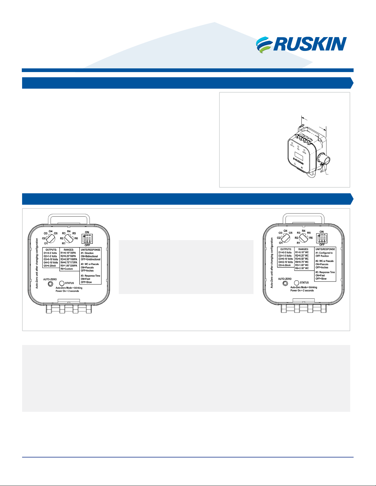
SWITCH SETUP - OUTPUTS, RANGES, UNITS/RESPONSE
AMS8100/AMS8100LR
Installation and Operation Instructions
AMS Series Transducers
Figure 1
Figure 2: Setup Switches for AMS8100LR & AMS8100
AMS Series Transducer with Display
PRODUCT IDENTIFICATION
1. Select desired OUTPUT range (O1 through O5)
2. Select desired PRESSURE range (R1 through R6)
3. Choose UNITS/RESPONSE options:
1. Direction – this is a plus/minus range, so choosing the 0.75”/175PA range (R4) equates to -0.75”/-175PA to +0.75”/+175PA Bi-directional
and 0” to +0.75” Unidirectional.
2. Choose UNITS - WC or Pascals
3. Response Time – Fast Response = ½ second; Slow Response = 4 seconds
4. Mount, Terminate, and Auto-Zero the unit as described in the following sections. Attach the deadhead tubing to the ports during Auto-Zeroing


