RUSTGO 139 Instruction Manual

Phone: 402-589-1247

MANUAL 2010 March
1
INTRODUCTION
TO
RUSTGO MANUALLY PROPELLED WORK PLATFORMS
The purpose of this manual is to provide the user with the thorough understanding of the proper operating procedures
necessary to comply with the intended use of the RUSTGO mobile work platform (manually propelled elevating aerial
platform).
Do not attempt to operate this work platform until you have read all the information in this manual and understand it.
Familiarize yourself with the unit’s functions and operations of the controls and have a good understanding of their
limitations and capabilities. Read all the various decals that are attached to this work platform before operating unit.
They contain important information regarding the safety and operations of this unit.
It is YOUR RESPONSIBILITY to follow procedures while operating this RUSTGO product. The manufacturer of this work
platform cannot control the wide range of applications that it may be used in carrying out a variety of jobs. Therefore, IT
IS THE USER’S RESPONSIBILITY to consider all of the personnel when making decisions regarding the intended use of
this work platform.
It is also YOUR RESPONSIBILITY to understand and obey all federal, state and local regulations regarding the operations
and use of manually propelled elevating aerial platforms. A copy of the ANSI/SIA A92.3-1990 Manual of
Responsibilities is included for your use.
DO NOT ALTER OR MODIFY THIS RUSTGO PRODUCT IN ANY MANNER
WITHOUT PRIOR WRITTEN APPROVAL FROM RUSTGO CO.
Many of the parts used in the manufacture of this RUSTGO mobile work platform have specific properties, and the
manufacturer recommends that replacement parts be purchased through RUSTGO CO. in order to ensure the original
integrity of the product. Repairs and adjustments should only be made by trained and qualified personnel. Please refer
to this manual for information on parts, service and maintenance of this RUSTGO product.
RUSTGO Co. reserves the right to modify, improve, add, and/or delete certain design features without obligation to
incorporate new features into previously sold products.

MANUAL 2010 March
2
MANUALLY PROPELLED WORK PLATFORMS
Are manufactured by
RUSTGO CO., 48926 State Hwy. 12, Spencer, NE 68777 USA
CLASSIFICATIONS OF RUSTGO MOBILE WORK PLATFORMS:
RUSTGO work platforms are categorized by the following ANSI Standard:
ANSI/SIA A92.3-1990 Manually Propelled Elevating Aerial Platforms
RUSTGO work platforms are categorized by the following OSHA Standard:
General OSHA Standard Part 1910
Subpart D 1910.29 Manually Propelled Mobile Ladder Stands and
Scaffolds (Towers)
(a) General requirements Section(e) Mobile work platforms
When in use in the field on a job site refer to 1926.452(w), then
(NON-MANDATORY) APPENDIX A TO SUBPART L – SCAFFOLD SPECIFICATIONS
1926.450(W) MOBILE SCAFFOLDS. Stability test as described in the ANSI A92 series documents, as appropriate for the type
of scaffold, can be used to establish stability for the purpose of Sec. 1926.452(w)(6).
RUSTGO mobile work platforms may be used as a guardrail system for fall protection. RUSTGO mobile work platforms
meet the OSHA requirements for a guardrail system under SUBPART M 1926.502 FALL PROTECTION SYSTEMS CRITERIA AND
PRACTICES (a) General and (b) Guardrail systems. Any additional requirements such as tying off, screens, mesh, etc. shall be the
users responsibility.
NOTE: RUSTGO mobile work platforms are not designed to withstand the forces imposed by the Personal fall arrest systems or
Positioning device systems as in OSHA Section 1926.502(d & e) Subpart M.
IMPORTANT: A COPY OF THE ANSI/SIA A92.3-1990 MANUAL OF RESPONSIBILITIES IS INCLUDED WITH THIS INSTRUCTION
MANUAL. IT CONTAINS IMPORTANT OPERATING INFORMATION FOR THIS RUSTGO PRODUCT. READ IT BEFORE OPERATING THIS
RUSTGO WORK PLATFORM.
When properly used in accordance with the listed OSHA requirements and ANSI standard RUSTGO manually propelled work
platforms meet said standards.

MANUAL 2010 March
3
GENERAL CODE OF SAFE PRACTICES
FOR
OPERATIONS OF MANUALLY PROPELLED WORK PLATFORMS
It shall be the responsibility of all users to read & comply with the following common sense rules which are designed to promote
safety in the operations of manually propelled work platforms. These rules do not purport to be all-inclusive nor supplant or replace
other additional safety & precautionary measures to cover usual or unusual conditions.
If these rules conflict in any way with any state, local, or federal statue or regulation said statute or regulation shall supersede
these rules and it shall be the responsibility of each user to comply therewith.
1. GENERAL RULES
A. SURVEY THE JOB SITE: A survey shall be made of the job site for hazards such as untamed earth fills, ditches, debris,
high tension wires, unguarded openings, hazardous conditions created by other trades.
B. INSPECT ALL EQUIPMENT BEFORE USING: Never use any equipment which has an obvious defect. Defective
equipment must be repaired before using.
C. NEVER USE EQUIPMENT FOR PURPOSES OR IN WAYS FOR WHICH IT WAS NOT INTENDED.
D. REPORT ANY UNSAFE CONDITION.
E. NEVER TAKE CHANCES: Do not work on platform if your physical condition is such that you feel dizzy or unsteady in any
way.
F. RUSTGO brand manually propelled work platforms are not insulated for use near electrically energized circuits. User
should therefore consider the work platform to be non-insulated unless otherwise labeled.
G. The operation of any work platform is subject to certain hazards that cannot be protected against by mechanical means
but only by the exercise of intelligence, care, and common sense. It is, therefore essential to have competent, careful
operators, physically and mentally fit and thoroughly trained in the safe operations of this type of equipment.
2. OPERATING RULES
A. FOLLOW ALL STATE, LOCAL, AND GOVERNMENT CODES, ORDINANCES AND REGULATIONS PERTAINING TO WORK
PLATFORMS.
B. Read manufacturer’s operating instructions. Never exceed manufacturer’s recommended load. All accessories must
be installed and used in accordance with manufacturer’s recommended procedures.
C. Perform daily maintenance checks and make visual inspection of work platform & surrounding area to be sure both are
clear of other personnel & obstructions.
D. Guardrails: Do not use machine without guardrails. Do not stand on guardrails to gain extra reach. Do not use
guardrails to carry materials.
E. Do not lean out over platform railings to perform work.
F. Do not use ladders or makeshift devices on the platforms to obtain greater height.
G. Do not operate equipment near electrical power lines (see enclosed additional information).
H. Care must be taken to prevent ropes, electrical cords, hoses, etc. from becoming entangled in equipment when
platform is being raised or lowered or equipment moved.
I. Do not alter equipment or override safety devices in any way.
J. Do not ride on platform while it is being moved.
K. Remove all material and equipment from platform before moving.
L. DO NOT OVERLOAD WORK PLATFORM.
M. Use proper guardrails and toe boards when required.
N. Consult your scaffolding supplier when in doubt. Never take chances.

MANUAL 2010 March
4
O. Employees shall not work on platforms during storms, high winds, freezing rain or other adverse weather conditions
that could endanger workman. Employees shall not work on platforms which are covered with ice, snow, or frost,
unless all ice, snow or frost is removed and decking sanded to prevent slipping.
P. Overhead protection shall be provided for employees on a platform exposed to overhead hazards.
DANGER: *DO NOT ALLOW MACHINE, PERSONNEL OR CONDUCTIVE MATERIALS INSIDE PROHIBITED ZONE.
*MAINTAIN M.S.A.D. FROM ALL ENERGIZED LINES AND PARTS AS WELL AS THOSE SHOWN.
*ASSUME ALL ELECTRICAL PARTS AND WIRES ARE ENERGIZED UNLESS KNOWN OTHERWISE
CAUTION: *DIAGRAMS SHOWN ARE ONLY FOR PURPOSES OF ILLUSTRATING M.S.A.D. WORK POSITIONS, NOT ALL WORK
POSITIONS.

MANUAL 2010 March
5
PRE-ERECTION JOB SITE INSPECTION & PREPARATION
The following guidelines are not all inclusive; rather they are examples of job site conditions to be aware of.
A survey of all obstructions, impediments or encumbrances that would pose a danger during the entrance onto the job site,
during the course of working on the job site and during the exiting of the job site should be taken prior to arrival of the equipment at the
job site.
This shall include, but is not limited to, aerial, ground and any buildings surveys. It shall include such potential hazards as:
Uneven ground, untamed earth fills, ditches/trenches, holes or depressions in the ground.
Electrical power, distribution lines. Guy wires
Protrusions from out of the ground or overheard from buildings or poles.
Debris, unguarded openings, hazardous conditions created by other trades or unauthorized people on the job site.
Weather conditions and forecasts and other possible unsafe conditions.
All potential hazards should be corrected or flagged and barricaded.
iThe common types of accidents scaffolding and mobile work platforms are most likely to be involved in are tip over,
collapse, and electrocution.
iTip over would most likely be caused by one or a combination of the following: wind, uneven ground conditions,
overloading and/or failure to keep uprights vertically plumb or failure to properly erect equipment.
iCollapse would most likely be caused by overloading or failure to properly erect equipment.
iElectrocution would most likely be caused by failure to lower platform(s) and/or remove the upright extensions to maintain
safe clearances of electrical power distribution lines. KNOW THE HEIGHT AND VOLTAGE OF ALL POWER LINES ON AND
ADJACENT TO THE JOBSITE. KNOW THE HEIGHT OF ALL EQUIPMENT AND MATERIALS BEING USED AT THE JOBSITE.
iTHE MAXIMUM HEIGHT OF A STANDARD MODEL 139 WITH THE MAIN PLATFORM FULLY EXTENDED IS APPROXIMATELY
23ft. 2in. (+ or – 2”) Approx. 7.06 meters
iTHE MAXIMUM HEIGHT OF A STANDARD MODEL 195 WITH THE MAIN PLATFORM FULLY EXTENEND IS APPROXIMATELY
29ft. 3in. (+ or – 2”) Approx. 8.9 meters

MANUAL 2010 March
6
--GENERAL INSPECTION & MAINTENANCE—
Daily visual inspection shall be conducted of the structural components and other critical components, such as pin, bolts and locking
devises (including pawls). Check for metal/weld fatigue on all parts including slide mechanism on platforms. Check for bent or worn
parts or components that need maintenance, repair or replacement. When parts or components need replacement, they shall be
identical or equivalent to original parts or components.
Environmental conditions such as acidic rain, salt water air or extremely wet conditions can have an impact on various equipment
parts and must be taken into account when determining if inspections should be made more frequently than the recommended
minimums. Amount of use and amount of towing should also be taken under considerations to determine if inspections should be
made more frequently than the recommended minimums.
The following are minimum frequency recommendations regarding the inspection and maintenance of the unit:
KEY: D-Daily W-Weekly M-Monthly
D 1. Check to be sure Instruction Manual is in Instruction Manual storage holder
D 2. ALL decals are in place and legible
D 3. Check brake handles, they should move easily. Oil or grease pivot.
D 4. Lock brakes. If wheels turn easily, re-adjust brake adjusting bolt on brake band until wheel is securely locked. If
wheels still turn, brake band linings are probably damaged-replace.
D 5. Check tire pressure & wear. Maintain maximum recommended tire pressure. Replace worn out tires. Tires
should be matched sets on each axle. Check lug nuts for tightness.
D 6. Front & Rear tongue bolts tight.
D 7. Is Rear steering tongue working properly. CHECK BEFORE TOWING ON STREETS & ROADS.
D 8. Check Extension Ladder safety catch; it should move freely.
D 9. Ladders should not have bent or broken rungs.
D 10. Check winch cables. If frayed or badly pinched, replace. Make sure Hair pin clips are in place.
D 11. All guardrails are straight, in place, and secured with ¼” safety pins.
D 12. Entry latches are in working order.
D 13. All x-brace are straight. Check for excessive wear or metal cracks at connections and/or brackets.
W 14. Inspect cable sheaves & clevis pins for wear. Lubricate with heavy oil or grease
W 15. Check lift arm ropes for wear and/or deteriorations, replace as needed.
W 16. If uprights or extensions have been bent or severely twisted-replace.
W 17. Grease inside lip of uprights to prevent lift arms from binding or dragging.
W 18. Grease adjusting arm threads, two zirks per arm. Oil ball joints located on each end of arms.
W 19. Grease platform slide brackets and inspect for cracks and/or metal fatigue.
W 20. All toe boards are in place and in good conditions.
W 21. Inspect decking for holes, soft spots or any other deterioration.
M 22. Grease front & rear axles, three zirks per axle.
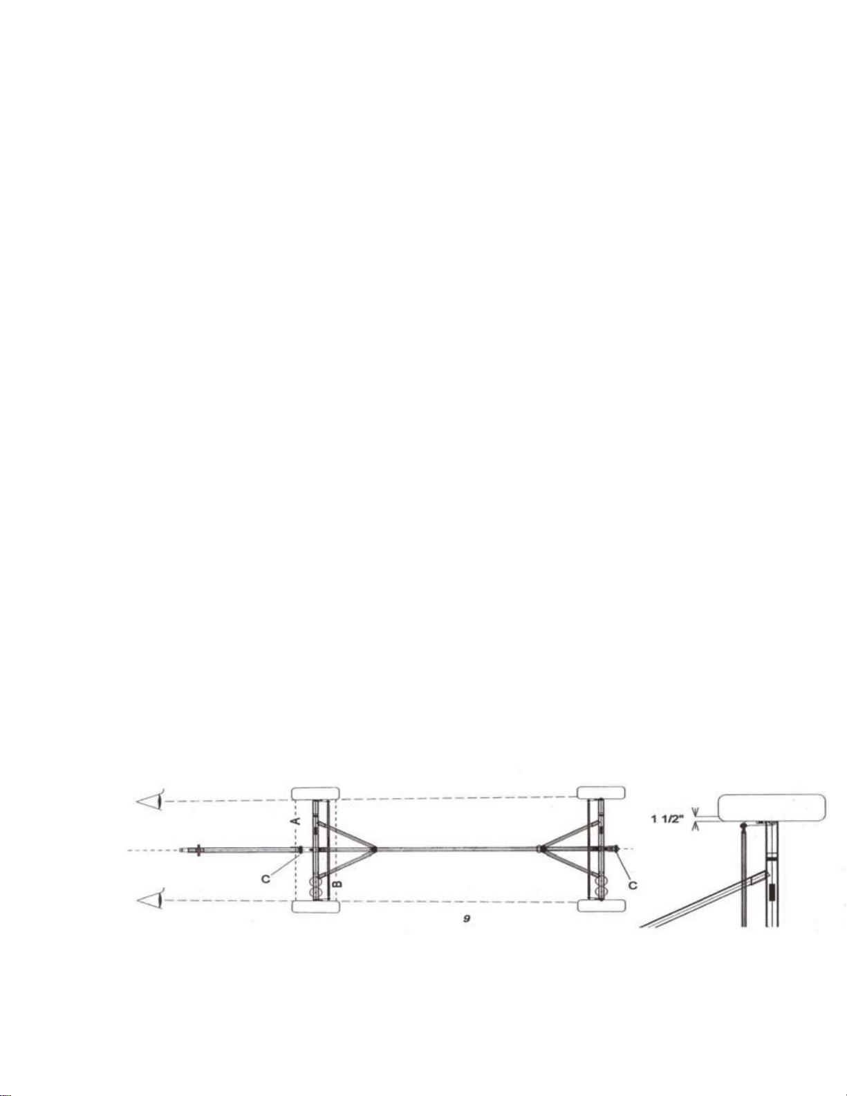
M 23. Check the wheel alignment for proper tow.
M 24. Grease wheel bearings and check for play. Should be repacked at a minimum-annually.
M 25. Inspect reach pipe bolts & square washers for wear.
M 26. Reach pipe is straight, not bent. CHECK BEFORE TOWING ON STREETS & ROADS.
M 27. Check spherical tierod ends for wear.
M 28. Inspect the lift arm pawls & springs for wear & tension.
M 29. Inspect all bolts for wear. Replace or tighten as needed.


MANUAL 2010 March
8
TROUBLE SHOOTING
If you have trouble raising and/or lowering the platform(s), check the following items:
1. Grease the inside lips of the front & rear uprights and upright extensions.
2. Grease the slide mechanism of the platform.
3. Be sure that the uprights are in line. If they are too out of line, the binding of the platform at the lift arm attachment pints
will transfer to the uprights and make it very hard to raise and/or lower the platform.
4. Is one or both of the uprights bent? Replace if needed.
5. Are the cables on the sheaves at the top of the uprights? Is the hair pin cotter in place to prevent cable from slipping off of
sheave?
6. Are the sheaves out of round or worn out? Replace entire sheave or brass busing insert. Oil brass sheave bushings.
7. Is the cable threaded through the space between the upright and the welded on backbone (u-shaped)? It should not be.
8. If you have a model 195 (goes to 25’6” deck height), do not thread the cable through the eye located just above the winch.
9. Is the winch free turning or is the cable wound over itself?
10. Check the welds of the slide mechanism, where it is welded to the platform. Are any of the welds broken? This would cause
the platform & slide to bind and work against each other.
TOWING
Poor towing can be a combination of several factors, including speed and road conditions. Check each of the following before
continuing to the “Guide to Proper Steering Alignment”.
1. Keep each axle free and non-binding.
2. Keep Front & Rear tongue bolts tight (snug).
3. A bent reach pipe or tie rod(s) can cause towing problems. Replace.
4. Use matched pairs of tires on each axle. Inspect tires for out-of-round or being severely out of balance.
5. Inspect rims for being out-of-bound or bent. Make sure the lug nuts have the rims securely on hubs.
6. Check for excess play of the wheel bearings.
7. Check for excess play of the tie rod ends and hairpin connections.
GUIDE TO PROPER STEERING ALIGNMENT
1. Keep all side play out of tongue by tightening 5/8” bolts at Point C.
2. FRONT TIRES: Align Front hairpin and tongue with center reach pipe and set tow in by sight or string as shown in drawing.
Viewed from the front, the point of projection on the Rear tire should be 1-1/2” from the inside face. (See Drawing Below).
The differential in measurement from the Front Point A to Rear Point B of the Front tires should be ½” to ¾”. With the
distance at Point A being the smaller of the two.
REAR TIRES: The Rear steering tongue must be in the latched position. Viewed from the rear, the Rear tires should align
with the front. The differential in the measurement of the front of the Rear tires to the back of the Rear tires should be 0”
or no toe in.

MANUAL 2010 March
9
UNCRATING & BASIC ASSEMBLE OF UNIT
UNCRATING
Inspect all crates or packages for damages. Report any damage or breakage to the delivering carrier. Break banding and
remove all parts from the deck of main platform. Break the banding securing platform to base skit and remove platform.
Remove all remaining parts from skid base.
GEAR ASSEMBLY
Install tires & rims on hubs (brakes are preinstalled).
The axles & corresponding tongues are stamped FRONT & REAR. Couple FRONT & REAR axles assemblies together with 2-
1/2” reach pipe. Using 2 ½”x4” bolts w/square washers on the top & bottom of reach pipe, secure with ½” locknuts. Attach
corresponding FRONT & REAR tongues to hairpins using 5/8”x4-1/2” bolts & locknuts.
MODEL 139 ONLY—ATTACHMENT OF COUNTER WEIGHTS
COUNTER WEIGHTS: MODEL 139
Bold 2 weights per axle onto gear in
pre-drilled holes on right side of
axles. Place counterweight w/angle
iron on top as shown.
IF APPLICABLE: Bolt intermediate
level carrying bracket (Part #192-129)
to angle iron as shown with
3/8”x2-1/4” bolts. Intermediate
level is then pinned to brackets using
3/8” safety pins. Tighten counterweight
bolts at this time.
Main 2’x20’ Platform
Install Instruction Manual tube. Install toe boards. Toe board installation diagram is with toe boards. Five ¼”x1-3/8” safety pins are
used to secure removable guardrails.
UPRIGHT ASSEMBLY
Sheaves are preinstalled.
1. Mount winch to upright 2-3/8”x1-1/2” bolts, thick washers, lock washers, and locknuts as shown in drawings. (This makes
two additional stops for the Intermediate Level).
2. Slide lift arm into upright from the lower end that pins to axle. Attach cable to lift arm using cable clevis.
3. Thread cable from lift arm up the inside of upright channel, over sheave and back down to winch and secure. DO NOT run
cable through channel on backside of upright. DO NOT thread cable through chain link eye located above winch on Model
195. Install hairpin clip in holes above sheave to keep cable on sheave. DO NOT attach 6ft upright extensions at this time.
4. Attach adjusting arms to uprights with 5/8”x2-1/2” bolts, locknuts & reducer bushings. Spinner wheel should be located at
the winch end of the upright. May be preassembled on Model 139.


MANUAL 2010 March
14
6FT. UPRIGHT EXTENSION ASSEMBLY
1. To attach, place extensions, x-brace pipes & ladder
Extensions on the platform and raise platform to within a
foot of the top uprights. Two 3/8” & two 3/4 “ safety
pins should be stored on the extensions when not in use.
This way the are readily available when installing
extensions.
2. Climb ladder, step onto platform & close gate. To
prevent possible injury from falling objects, the area
below the work platform shall be clear of workman while
the upright extension assembly is being attached. While
standing on platform, remove hairpin cotter from rear
upright and pull up enough slack (2-3ft) in the cable to
lay cable off the th side of upright.
3. Remove the 3/4 “ pin from rear extension. With a firm
grip, stand up extension, slide into place on top of the
upright & secure with 3/4”. Pull up enough cable slack to
place cable on sheave at the top of the upright extension
and insert hairpin cotter at top of extension. Repeat
procedure to install the front upright extension.
NOTE: Rear extension has ladder bracket.
4. Pin one extension x brace, at a time, to the top of each
extension using 3/8” safety pins provided. Reach down
and “walk” the bottom of an x-brace to the other upright
and secure to the top pin holes of the upright head
section using a 3/8” safety pn. Repeat with other
extension x-brace. These 2-3/8” pins should be stored in
these holes when the upright extensions are not being
used.
5. Install ladder extension on rear upright extension. The
tabs at the bottom of the extension ladder should be
started into the top end of the main ladder before
securing upper ladder rung/safety toggle into ladder
bracket on extension.
TOGGLE SHOULD BE KEPT FREE AND NONBINDING
SPECIAL NOTE:
STORE 3/4" SAFETY PINS FOR EXTENSIONS ON THE
EXTENSIONS, NOT ON THE TOP OF THE UPRIGHTS.
NEVER SET UP THE UNIT WITH THE 6’ EXTENSIONS
ATTACHED TO THE UPRIGHTS. ALWAYS ATTACH THEM
AFTER THE UNIT HAS BEEN SET UP.
The winches provided for use on these units have a friction pad to prevent or lessen spooling of the cables.
The winches are still free spooling with respect to supporting the platforms. The notch systems is still the
method of support for the platforms

MANUAL 2010 March
15
INSTALLATION & USE OF
I NTERMEDIATE LEVELS
1. When using a unit that has intermediate Level Inches,
remove the handle of the main winch and place it on the
intermediate Level Winch.
2. Insert guide pins ( located at the top) of Intermediate Level
Lift Arm into the bottom of the upright channel. (PHOTO 1)
3. Raise arm until it comes into position (NOTE: Notches
on bottom of lift arm) so the notches on the bottom
end of the lift arm will slip into the upright channel lips.
(PHOTO 2)
4. Raise lift arm until pawl engages a notch on the
upright channel. Unwind I/L winch to provide enough
cable slack to attach link snap into loop welded on face
of lift arm. Take up cable slack with I/L winch.
(PHOTO 3)
5. Place Intermediate Level on lift arms(with gate end
near ladder) as you would a main platform. Secure with
2-3/8” safety pins provided. Due to the weight of the
platform, you may wish to use lifting equipment, such
as a forklift, to initially place the platform on lift arms.
6. To raise, crank clockwise on the I/Level winch.
Raising (PHOTO 4) and lowering (PHOTO 5) the
Intermediate Level using the I/Level winches is
accomplished in the same manner as the main platform.
(See RUSTGO GENERAL OPERATING INSTRUCTIONS
page for full explanation.)
If you are using two Intermediate Level, the lower one is
raised & lowered in the same manner as the upper one.
Detach Link Snap from upper I/L lift arm and reattach to
lower platform. Repeat procedures for raising and
lowering.
In addition to the rope, the Intermediate level lift arms
are provided with a cable, sheathed in vinyl tubing, to
lower the platform the final few feet, if so desired. To
lower, raise platform slightly, grasping the cable and
angled brace squeeze cable to disengage pawl from
notches and carefully let platform down to desired
height. Then release cable to engage pawl in notch or
remove from unit.
NOTE: When you lower the Intermediate level down to
the bottom 2 stops (winch bolts) of the upright, you are
not able to move the main (2’x20’) platform because
the winch handle will not clear the I/Level platform.

MANUAL 2010 March
16
RUSTGO GENERAL OPERATING INSTRUCTIONS
The Rustgo mobile work platform is designed to easily adjust to most terrain encountered on a job site. However, good judgment
and common sense must be exercised to use this product in a safe manner. Care must be taken to maintain good stability &
adequate clearance of the unit while maneuvering & using the unit on the job site. SEE: PRE-ERECTION JOB SITE INSPECTION &
PREPARATIONS before assembling & using unit.
When maneuvering the unit around the job site it is a good practice to lower the platforms as low as possible and to slightly adjust
the platform away from the building or work area using the spinner wheels on the two adjusting arms. This is done to help avoid
potential electrical contact, and/or damage to the building or work area. When in doubt, always remove extensions to avoid
potential electrical contact.
Using front & rear steering, roll the work platform up to and along side of the building or work to be done. NOTE: You’ll find it
easier steering into place if each person concentrates on positioning their own and instead of watching where the other end is going.
THIS DOES NOT MEAN IGNORING POTENTIOAL HAZARDS THE OTHER END MAY BE APPROACHING. After moving into desired
position, LOCK ALL FOUR WHEEL BRAKES. Plumb the uprights using the spinner wheels on the adjusting arms.
TO RAISE PLATFORM:
Raise and level the main 2’x20’ platform to the desired height using the winches provided on the uprights. Keep a firm grip on the
winch handle, these are free spooling to allow positive engagement of the pawl into the upright notches. As you raise the platform
you will notice a clicking sound, this is the pawl slipping over the notches. To insure that the pawl is engaged in a notch after
reaching the desired height, it is a good practice to raise the platform slightly, about 1-2 inches, and back off the winch. You will be
able to feel the contact of the pawl and notch. The cable should now be slack.
TO LOWER PLATFORM:
Raise platform by ¼ turn of winch. Pull down on rope and hold. Lower platform using winches, keeping a steady downward pull on
the ropes and a firm grip on the winch handles. When platform is lowered to desired height, release rope and winch down until you
feel and hear the pawl engage one of the notches in the upright. To insure that the pawl is engaged in a notch after reaching the
desired height, it is a good practice to raise the platform slightly, about 1-2 inches and back off the winch. You will be able to feel
the contact of the pawl and notch. The cable should now be slack.
NOTE: When moving a unit over rough, uneven or sloping ground other factors come into play. This is a judgment call that can only
be made in the field. To reduce sway and increase stability you may want to:
1. Lower the platform(s) as far as possible, thereby lowering the center of gravity. You may also want to lower the platform(s)
to avoid potential overhead hazards. If overhead electrical power lines are present you must lower the platform(s) as far
as possible to provide adequate clearance. If necessary you may need to remove Intermediate Levels and/or 6ft. Upright
Extensions. This unit is NOT insulated. It shall not be used near electrically energized circuits or power lines without
adequate safety measures being taken. Refer to MINIMUM SAFE APPROACH DISTANCE (M.S.D.A.) GUIDELINES. Contact
your local, state, federal safety agencies and/or your local electrical utility for more information concerning the safe
distances, safety measures and voltage of power lines on or near the job site.
2. Plumb the uprights using the adjusting arms if they start getting excessively out of plumb while moving the unit.
3. All counterweights must be on the unit, use all parking brakes and the work platforms shall not be raised, lowered, or
moved with workmen on platform(s).
4. Read & understand warning decals on unit. Follow the rules from the “General Code of Safe Practices of Operation of
Manually Propelled Work Platforms”.
5. After disassembly for tow, secure various parts on the platform(s) using provided tarp straps (Part# 486-128) or ratchet
straps (Part# 486-129_.

MANUAL 2010 March
17
TRANSPORTING YOUR WORK PLATFORM
MODEL 195 MODEL 139
TRAIL POSITION IN TRAIL POSITION
Shown above is an example of a Model 195 Shown above is an example of a Model 139.
in trial position for highway tow. The example in trail position for highway tow. The example
consists of a Model 195 with optional wide tires, consists of a Model 139 with optional wide tires,
2” ball hitch, and 2 Intermediate Levels. Saddle 2” ball hitch, 1 Intermediate Level, and a Light Bar.
weights are not to be lift on unit when towing To tow, in trail position, adjusting arm threads
and should not be transported separately. Must be screwed completely in to give a clearance
ofapproximately13ft.5in.
When readying for tow behind a vehicle, be sure REAR STEERING TONGUE IS LOCKED DOWN IN PLACE
ADDITIONAL WINCH OPERATING INSTRUCTIONS
WHEN LOWERING THE PLATFORM(S) ONLY 1 PERSON SHOULD BE OPERATING THE WINCH AND
RELEASE ROPE FOR EACH WINCH. THE OPERATOR SHOULD NOT BE UNDER THE PLATFORM.
THE OPERATOR SHOULD FIRMLY GRAB THE WINCH IN ONE HAND AND THE ROPE IN THE OTHER.
IF YOU LOSE YOUR GRIP ON THE WINCH, RELASE THE ROP.
DO NOT ALLOW ANYONE EXCEPT THE WINCH OPERATOR TO HOLD THE ROPE.

MANUAL 2010 March
18
THIS
PAGE
IS
INTENTIONALLY
LEFT
BLANK

This manual suits for next models
1
Table of contents