Standard
Der LED-Strip ist nur für die Installation in tro ckenen
Innenräumen geeignet.
Stromschlagge ahr!
Beauftragen Sie mit der Installation eine Elektrofach kraft.
Für Leuchten, die nicht gemäß den euro päischen
Sicherheitsrichtlinien installiert wurden, entfällt jeder
Haftungsanspruch.
Achtung!
LED-Strip nur an ein geeignetes Netzgerät
(24 V DC) anschließen.
Nur komplett abgerollt betreiben.
LED-Strips in Parallelschaltung verbinden.
Lie erum ang
1 x 5 Meter LED-Strip
5 x Einspeisungsverbinder
1 x Direktverbinder
Technische Daten
Spannungsversorgung 24 V Netzgerät mit konstanter
Ausgangsspannung
Leistung 17,5 W
Stromstärke 0,729 A
Ausstrahlwinkel 120
Anzahl LED 240
Länge Maximal 5 Meter pro Anschluss
Abmessungen 5000 x 8 x 2,2 mm
Biegedurchmesser 40 mm
CE-konform mit den zutreffenden
europäischen Richtlinien
Schutzklasse 3 - Schutzkleinspannung
Nur für den Innenbereich geeignet
Do not cover lamps with heat-
i
Ensure that minimum
c
Use HO3VVH2-F 2x 0.75 mm cable only
f
Use low-pressure halogen
l
The lamp is suitable for moun-
t
T
L
Protection class 3 – Low-voltage 12 V.
U
Use low-voltage traction relief (except
f
H
This is only possible with specially
m
Protection class 2 – high vol-
t
Switch off voltage prior to installation.
E
Do not touch the halogen lamp with
y
DD
Bild 1
Bild 2
Beispielabbildung
Beispielabbildung
Carl-Zeiss-Str. 15
28857 Syke
Standard_BA_8431ff_01/2019
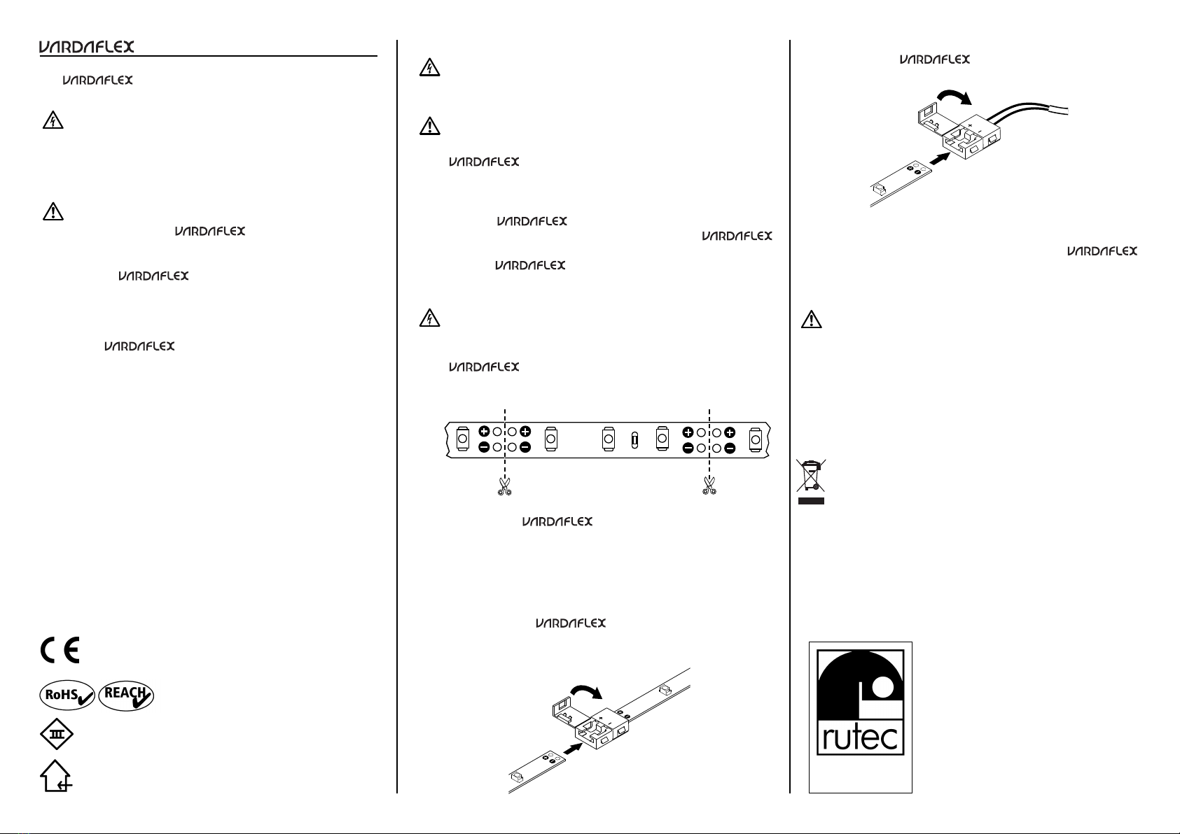
Mit Einspeisungsverbinder:
Um einen LED-Strip mit einem Netzgerät zu
verbinden, verwenden Sie einen Einspeisungverbinder.
1. Schutzfolie an der Verbindungsstelle nicht ent ernen.
2.
Verschluss des Direkt-/Einspeisungsverbinders öffnen
(Bild 2+3).
3.
Direkt-/Einspeisungsverbinder auf das Ende des
LED-Strips ste cken (Polung beachten) und den Verschluss
schließen (Bild 2+3).
Achtung!
Bei Lötverbindungen beachten: Löttemperatur 260 C und
Lötdauer maximal 10 Sekunden.
Es ist ausschließlich neutral vernetztes Silikon zu verwen-
den (keines alls essighaltiges Silikon verwenden!).
Entsorgung
Entsorgen Sie elektrische und elektronische Geräte
umweltgerecht. Nähere Informationen erhalten Sie bei
Ihrer zuständigen Behörde.
Do not cover lamps with heat-
i
Ensure that minimum
c
Use HO3VVH2-F 2x 0.75 mm cable only
f
Use low-pressure halogen
l
The lamp is suitable for moun-
t
T
L
Protection class 3 – Low-voltage 12 V.
U
Use low-voltage traction relief (except
f
H
This is only possible with specially
m
Protection class 2 – high vol-
t
Switch off voltage prior to installation.
E
Montage
Stromschlagge ahr!
Vor der Installation Spannung abschalten. Sicherstellen, dass
die Spannung nicht versehentlich wieder eingeschaltet werden
kann.
Achtung!
Bei stromführenden Oberflächen Isolierschicht zwischen
LED-Strip und Oberfläche anbringen. Ober -
flächen müssen eben, staub- und fettfrei sowie trocken sein.
1. Oberfläche vorbereiten.
2. LED-Strip, falls erforderlich, kürzen (Bild 1).
3. Schutzfolie abziehen und LED-Strip mit leichtem
Druck anpressen, dabei nicht direkt auf die elektronischen
Bauteile drücken.
4.
LED-Strip an Spannungsversorgung anschließen.
LED-Platine kürzen
Stromschlagge ahr!
Vor dem Kürzen immer spannungsfrei schalten.
LED-Strip kann jeweils nach sechs LEDs (125 mm)
getrennt werden (Bild 1).
LED-Strip an der markierten Stelle trennen.
Bei eng bestückten LED-Strips wird ein Mikroseitenschneider
oder optional ein Cutter benötigt
!
LED-Platine verbinden
Mit Direktverbinder:
Um zwei LED-Strips miteinander zu verbinden,
verwenden Sie einen Direktverbinder.
Do not cover lamps with heat-
i
Ensure that minimum
c
Use HO3VVH2-F 2x 0.75 mm cable only
f
Use low-pressure halogen
l
The lamp is suitable for moun-
t
T
L
Protection class 3 – Low-voltage 12 V.
U
Use low-voltage traction relief (except
f
H
This is only possible with specially
m
Protection class 2 – high vol-
t
Switch off voltage prior to installation.
E
Do not touch the halogen lamp with
y
Bild 3
Beispielabbildung