HOSE CONNECTIONS FOR STANDARD ABOVEGROUND POOLS
HOSE CONNECTIONS FOR TEMPORARY ABOVEGROUND POOLS
AC 124EZ5G and FILTERS EQUIPPED WITH AC 22764 FITTINGS
10
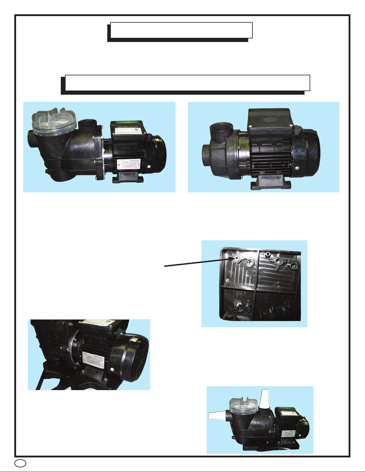
1. Take the short hose. Place a clamp onto each end of the short hose. Leave loose.
Slide one end of the short hose over the exhaust port of you pump. This is the port
opening at the top of the pump not the one in front of the pump. Once in place tighten
that clamp. Take the other end of the short hose and slide it onto the port of the multi-
port valve labeled PUMP. This port is identified by the word “PUMP” embossed on the
side of the port on the vale itself. Tighten the clamp.
2. Take one of the long hoses. Place a clamp onto each end of the hose. Again leave
them loose. Slide one end of the hose over the intake port of the pump. This is the port
attheveryfrontofthepump.Tightentheclamp.Taketheotherendofthe6’hoseand
slide it over the port of the pools thru wall skimmer. Once in place tighten the clamp.
3. Take the remaining long hose. Place a clamp over each end of the hose, again
loosely. Slide one end of the hose over the port on the multiport valve labeled “POOL”.
The word “POOL “is embossed next to the correct port on the valve. Once in place
tightenclamp.Taketheotherendofthe6’hoseandslideitoverthepoolsreturnfitting
connection on the outside of the pool wall. Once in place tighten the clamp.
1. Take the short hose. Place a clamp onto each end of the short
hose. Leave loose. Slide one end of the short hose over the
exhaust port of you pump. This is the port opening at the top of
the pump not the one in front of the pump. Once in place tighten
that clamp. Take the other end of the short hose and slide it onto
the port of the multiport valve labeled PUMP. This port is identified
by the word “PUMP” embossed on the side of the port on the vale
itself. Tighten the clamp.
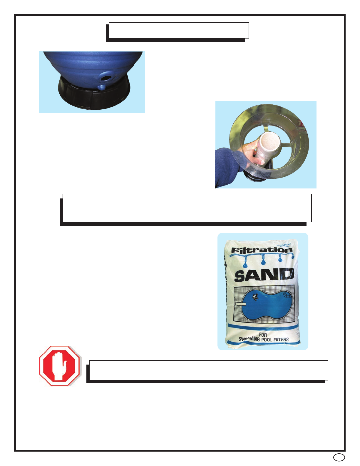
2. Take one of the long hoses. Place a clamp onto each end of the
hose. Again leave them loose. Slide one end of the hose over the
intake port of the pump. This is the port at the very front of the
pump.Tightentheclamp.Taketheotherendofthe6’hoseand
slide one of the AC 22764 fittings onto the end and tighten the
clamp. Attach the fitting (now connected to the hose) to the
suction/intake port of your temporary pool. Hand tighten fitting.
3. Take the remaining long hose. Place a clamp over each end of
the hose, again loosely. Slide one end of the hose over the port
on the multiport valve labeled “POOL”. The word “POOL”
is embossed next to the correct port on the valve. Once in place
tighten clamp. Take the other end of the long hose and slide the
other AC 22764 fitting into the end and tighten the clamp. Attach
the fitting to the pools return port on the outside of the pool wall.
Hand tighten fitting
AC 22764