RYCO RY20C User manual

OPERATION MANUAL
MOBILE AND WORKSHOP SERIES
CONNECTING PARTNERSHIPS
FOR MODELS:
RY20C
RY20CB
RY32C
RY32CB October 2018 | Version: v1-0


1MOBILE AND WORKSHOP SERIES OPERATION MANUALOctober 2018 | Version: v1-0
CONTENTS
GENERAL...................................................................................................................................................................2-6
HECKLIST............................................................................................................................................................................................................. 3
Pre-Delivery Checklist............................................................................................................................................................................................ 3
Pre-Commencement Inspection ............................................................................................................................................................................. 3
SAFETY............................................................................................................................................................................................................. 4-11
Restriction ............................................................................................................................................................................................................. 4
Danger Zones ........................................................................................................................................................................................................ 5
Safety Notes .......................................................................................................................................................................................................... 5
Hose Assembly...................................................................................................................................................................................................... 5
Machine Installation ............................................................................................................................................................................................... 5
Safety Instruction................................................................................................................................................................................................... 6
Battery and Oil....................................................................................................................................................................................................... 7
Oil Fill.................................................................................................................................................................................................................... 7
Running-In............................................................................................................................................................................................................. 7
Greasing................................................................................................................................................................................................................ 7
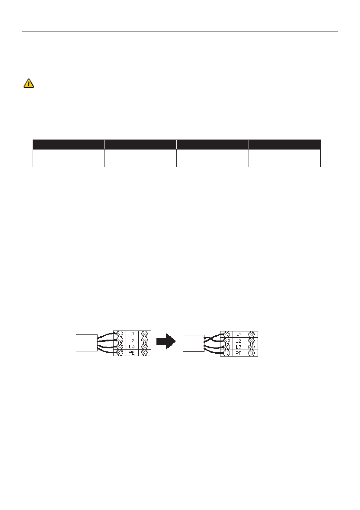
Installation of Power Supply................................................................................................................................................................................... 8
Transporting .......................................................................................................................................................................................................... 9
Base Mounting....................................................................................................................................................................................................... 9
Danger Zones and Warning Labels ..................................................................................................................................................................10-11
OPERATION............................................................................................................................................................12-17
START UP..............................................................................................................................................................................................................12
Hydraulic System..................................................................................................................................................................................................12
Functional Tests and Re-Testing...........................................................................................................................................................................12
SELECTING THE DIE SETS ......................................................................................................................................................................................13
RY20 Die Sets ......................................................................................................................................................................................................13
RY32 Die Sets ......................................................................................................................................................................................................13
MOBILE AND WORKSHOP SERIES ...........................................................................................................................................................................14
Start Up ................................................................................................................................................................................................................14
Operation..............................................................................................................................................................................................................14
Installing The Die Set............................................................................................................................................................................................14
QUICK CHANGE TOOL.............................................................................................................................................................................................15
Quick Change Tool ...............................................................................................................................................................................................15
Change of a Single Die Set ..................................................................................................................................................................................15
CONTROL IDENTIFICATION.....................................................................................................................................................................................16
Digital Control Panel .............................................................................................................................................................................................16
Crimping ..............................................................................................................................................................................................................17
SPECIFICATIONS ....................................................................................................................................................18-22
RY20C..................................................................................................................................................................................................................18
RY32C..................................................................................................................................................................................................................19
RY20CB ...............................................................................................................................................................................................................20
RY32CB ...............................................................................................................................................................................................................21
Calibration ............................................................................................................................................................................................................22
MAINTENANCE.......................................................................................................................................................23-24
HOW TO MAINTAIN YOUR CRIMPER.........................................................................................................................................................................23
Cleaning ...............................................................................................................................................................................................................23
Lubrication/Greasing.............................................................................................................................................................................................23
Oil Change ...........................................................................................................................................................................................................23
Master Spring Change ..........................................................................................................................................................................................23
Pressure Pipes .....................................................................................................................................................................................................23
Troubleshooting ....................................................................................................................................................................................................24
TECHNICAL ............................................................................................................................................................25-34
ELECTRICAL SCHEME ............................................................................................................................................................................................25
Electrical Components List - RY20CB/RY32CB .....................................................................................................................................................26
Electrical Components List - RY20C/RY32C..........................................................................................................................................................27
ASSEMBLY ............................................................................................................................................................................................................28
Assembly of RY20/RY32.......................................................................................................................................................................................28
Assembly of RY20CB/RY32CB .............................................................................................................................................................................29
Assembly of RY20C/RY32C ..................................................................................................................................................................................30
Master Die Misalignment Troubleshooting ........................................................................................................................................................31-34

2MOBILE AND WORKSHOP SERIES OPERATION MANUAL October 2018 | Version: v1-0
GENERAL INFORMATION
GENERAL
Do not unpack or operate the crimping machine until you have thoroughly read this manual.
All operators using the crimping machine must read this manual.
This manual provides necessary information for the safe use of this machine.
This manual is the result of continual development, testing and technical evaluations that are registered and veried according to
2006:42/EG, 2004:108/EG, 2006:95/EG, EN614-2, 97/23/EG.
The information within this manual is intended only for trained operators who can operate the machine without risk to themselves,
other persons, property, the machine, or the environment. The operator should have proven competence in
• Trouble-shooting methods
• Performing machine inspections
• Simple maintenance procedures
• Safe hose making practices and procedures, in compliance with, this manual, appropriate legislation and RYCO
Hydraulics Safe Work Instructions.
The scope of this manual does not cover disassembly or comprehensive maintenance procedures. These may only be performed
by an authorised service technician.
Store this manual and keep it in good condition for future use. Contact your nearest authorised RYCO distributor for replacement
manual or additional information if required.
RYCO is not liable for injury/damage to persons/machine or property as a result of improper use, having made prohibited
modications to the machine or misinterpreting this manual’s safety instructions.
The machine is transported on a pallet, which is easy to move and lift with a fork-lift truck. After unpacking, the machine should be
lifted using an approved, appropriately rated lifting sling.
Warranty
The warranty lasts one (1) year from purchase and only under the strict condition that the manual instructions have been followed.
The warranty covers defected material/parts and awed workmanship, replacing defected parts cost.
The warranty does not cover improper use or normal wear. Travel costs, time for repair and shipping costs are not covered by the
warranty. Repairs under the warranty are to be made only by RYCO or an authorized service technician approved by RYCO.
Lost income or extra costs that may arise for any reason are not covered by the warranty.
Please contact RYCO to discuss warranty claims.

3MOBILE AND WORKSHOP SERIES OPERATION MANUALOctober 2018 | Version: v1-0
CHECKLIST
GENERAL
Pre-Delivery Checklist
Pre-Commencement Inspection
RY20C/RY32C RY20CB/RY32CB
Crimper wrapped in plastic and packed in a
suitable box for Air & Sea freight
Crimper wrapped in plastic and packed in a
suitable box for Air & Sea freight
Grease Cartridge RY20CB or RY32CB Crimper complete with
base/die storage
Grease Application Tool Foot Pedal
Technical User Manual Grease Cartridge
Manual Change Tool Grease Application Tool
Die Pins Technical User Manual
Back Stop
Quick Change Tool
Manual Change Tool
Die Pins
Die Sets
RY20
Included Dies
RY32
Included Dies
Optional Dies
If Ordered
14mm 63mm 7mm
16mm 69mm 10mm
19mm 74mm 12mm
22mm 78mm
26mm
30mm
34mm
39mm
45mm
Before using the crimper for production, this checklist should be performed using procedures outlined herein.
Check RYCO logo, safety labels and Crimp Chart decals are attached.
Grease cone-shaped surfaces in the cylinder.
Check for no abnormal noise during operation across full range of motion.
Check all dies are supplied and appropriately numbered.
Check calibration as per calibration procedure.
RYCO recommend a risk assessment be performed by the end-user prior to installation and use.

4MOBILE AND WORKSHOP SERIES OPERATION MANUAL October 2018 | Version: v1-0
SAFETY RULES
GENERAL
These Hydraulic Crimping Machine are for crimping hydraulic hose and couplings made by RYCO Hydraulics. The design &
construction of this machine conforms to local and safety design standards.
Industry Standard Year Title Standard Description
DIN EN ISO 12100-1 2004 Safety of machinery Safety of machinery. Basic concepts, general principles for
design basic terminology, methodology.
DIN EN ISO 12100-2 2004 Safety of machinery Safety of machinery. Basic concepts, general principles for
design. Technical principles.
EN 414 1992 Safety of machinery Rules for the drafting and presentation of safety standards.
EN 1050 1996 Safety of machinery Risk assessment.
EN 294 1992 Safety of machinery Safety distances to prevent danger zones being reached by the
upper limbs.
EN 982 1997 Safety of machinery Safety requirements for air power systems and components -
hydraulic.
EN 60204-1 1997 Safety of machinery Electrical equipment of machines. Part 1.
EN 61000-6-2 2005 Electromagnetic Compatibility Generic emission standard.
EN 61000-6-4 2005 Electromagnetic Compatibility Generic immunity standard.
Restriction
RYCO crimping machines are electrically operated hydraulic crimping machines for hydraulic hose assemblies. Machines are
designed for single piece and low production. The crimping machine comprises a crimping head, a hydraulic unit.
Generally, these machines will be installed under the following conditions:
1. Supply voltage: 0.9 - 1.1 nominal supply voltage
2. Source frequency: 0.99 - 1.01 nominal frequency
3. Ambient temperature: 5°C - 40°C (40°F - 104°F)
4. Altitude: shall be at altitudes up to 1000m above sea level
5. Relative humidity: not exceed 50% at 40°C (104°F)
6. Atmosphere: Free from excessive dust, acid fume, corrosive gases and salt.
7. Avoid exposing to direct sunlight or heat rays which can change the environmental temp.
8. Avoid exposing to abnormal vibration.
9. Greased frequently.
These machines are designed for certain applications only. We strongly recommend that the machines are NOT modied and/or
used for any application other than for which they are designed. If you have any questions relative to its application DO NOT use
the machine until you have had detail instruction from your RYCO representative.

5MOBILE AND WORKSHOP SERIES OPERATION MANUALOctober 2018 | Version: v1-0
GENERAL
SAFETY
Danger Zones
General Warning Label
Pay particular attention to these items.
Crimping Hose Assembly Label
When crimping a hose assembly, hold the hose far enough away to avoid any pinch or crush zones.
No Hands Label
Do not put your hands in these areas while the motor is running.
RY20/RY32
1. The Installation site for the machine must provide an adequate clear work area around the crimper.
2. A clear area must be provided along the base dimensions of the machine that’s essential to permit efcient
maintenance and assembly.
3. Refer the Technical Data section for space requirements.
To maintain stability, leveled mounting pads should be used under the four xing points at the base of the machine.
Machine Installation
Appropriate Personal Protective Equipment (PPE) must be worn during hose making and maintenance activities.
• This equipment should only be used by qualied, trained persons who are familiar with this equipment.
• To avoid personal injury, keep hands and feet away from crimper and workpiece during operation.
• Do not exceed equipment ratings. Overloading causes equipment failure and possible personal injury. The crimper is designed
for a max. pressure of 275 bar (4,000 psi).
• Never Set the relief valve pressure above 300 bar (4,350 psi). Serious personal injury could result if this maximum limit is
exceeded. Damage to crimper pump and components may also occur.
• Keep hydraulic equipment away from ames and heat. Excessive heat will soften packings and seals, resulting in uid leaks.
Heat also weakens hose materials and packaging. For optimum performance do not expose equipment to a Temperature of
50°C (122°F) or higher. Protect hoses and cylinders from weld spatter.
Safety Notes
Hose Assembly
Should a hydraulic hose rupture, burst or need to be disconnected, immediately shut off the pump and shift the control valve
to release all pressure.
• Never grasp a leaking pressurized hose with your hands.
• Always keep the hose away from re, sharp surfaces, heavy impact and extreme heat or cold. Never kink, twist, curl or
bend the hose so tightly that the oil ow within will be blocked or reduced.
• Always inspect the hose for wear periodically, as any of these conditions can damage the hose and possibly result in
personal injury.
• Hose material and coupling seal must be compatible with the hydraulic uid used.
• Hose must not come in contact with corrosive materials.
• Never paint a coupling, hose will deteriorate due to toxic materials.
• Never use the hose to move attached crimper. Stress can damage the hose and may cause personal injury.

6MOBILE AND WORKSHOP SERIES OPERATION MANUAL October 2018 | Version: v1-0
SAFETY
GENERAL
1. For your safety read instruction manual before operating the machine:
Operators of this equipment must read and understood the content of the manual, be adequately trained and evidence
competence in producing hydraulic hose assemblies utilising the crimper.
2. Earth all machines:
A terminal for the connection of the external ground conductor is provided in the vicinity of the associated phase conductor
terminals marked "PE". The "PE" terminal must be connected by a suitably qualied person.
3. Work environment:
Don't use machines in damp or wet locations, or expose them to rain. Ensure working area is well lighted and ventilated.
Do not operate electrical machines near potentially explosive environment.
4. Children and visitors:
All children and visitors should be kept at a safe distance from work area.
5. PPE apparel:
No loose clothing, neckties, rings, bracelets or other jewelry which have the potential to get caught in moving parts.
Wear protective hair covering to contain long hair. Gloves should be worn while operation, cleaning and during repairs.
6. Repairs:
Be aware of fatigue. Do not operate machine when you are tired.
Please stand in front of machine for proper position operation.
7. Disposal of packing material:
Please check local environmental regulations before disposing of packing materials.
Explore recycling opportunities to avoid disposal in land ll sites.
8. Unintentional starting:
Ensure control panel switches are in the OFF position before isolating the main power supply.
Never leave the machine running unattended.
9. Maintenance:
Shut down the machine and follow the appropriate Lock Out procedures before any inspections, maintenance
and adjustment.
10. Emergency Shutdown:
The emergency shutdown button is colored red with a yellow background located on the control panel.
11. Electrical equipment:
Keep all electrical equipment dry and in a good working order.
Electrical equipment will withstand the effects of transportation and storage temperature within the range of
-25oC to 55oC (-13°F to 130°F) and for short periods (not exceeding 24 hours) up to +70°C (158°F).
12. Machine storage:
If the machine is not to be operated for a long period of time it should be stored in a dry environment with the appropriate
protection against ingress of dust and moisture. During storage, main power supply should be disconnected.
Safety Instruction

7MOBILE AND WORKSHOP SERIES OPERATION MANUALOctober 2018 | Version: v1-0
SAFETY
GENERAL
Follow procedures herein to ll the RY20 or RY32 oil reservoir with hydraulic oil the
equivalent of RYCO Hydraulic Oil 46. It is recommended to pump the oil into the reservoirs
through a 20μ lter, to avoid transferring impurities. If any oil spills, clean up immediately
with a RYCO Spill Kit.
Oil Fill
Battery and Oil
These items are governed by International shipping requirements. Generally they will not have
batteries installed and will be delivered dry. Check the oil tank and ll as required prior to use
using procedure herein.
RYCO SPILL KIT
RYCO HYDRAULIC OIL
The Master Dies are greased at the point of manufacture after nal testing. This should not be relied on to protect the crimper
during initial use. Prior to commissioning, the machine should be greased according to operating Instructions.
Greasing of the master dies is critical to ensuring a long and trouble-free life for the crimper. Greasing frequency should be
increased when operating in aggressive or high volume environments.
Greasing
Running-In
Recommended run-in period for a new machine is 20 crimps.
It is recommended the greasing process is carried out at least twice a day, more if the machine is in constant use.
The purpose of frequent greasing is to ensure that there is always enough grease between the sliding surfaces.
Due to the surface pressure the grease sinks in to the metal pores ensuring good sliding properties for the machine’s lifetime.
During the run-in period grease the machine after every 100 crimps.

8MOBILE AND WORKSHOP SERIES OPERATION MANUAL October 2018 | Version: v1-0
Installation of Power Supply
1. The machine should be connected to the protective-earth terminal between machine and external ground before connected
to the power source.
2. The cross-section of incoming supply protective conductor and each phase conductors must be in accordance with the
following reference of supply conductor table. It is important to identify the machines voltage requirements.
The voltage requirements should be marked on the machines electrical cabinet.
Model Recom. Fuse (400V) Supply Wire Size PE Wire Size
RY20CB 25A>FUSE>20A 5.5mm25.5mm2
RY32CB 25A>FUSE>20A 5.5mm25.5mm2
3. Power supply connection, always connect the earth conductor with yellow/green color before the connection of the other
power conductor.
4. 1-Phase: Connect the phase and the neutral to the respective terminals in the supply disconnecting device.
Connect the earth connection to the ground terminal on the xing plate. Check the connection against the wiring diagram
enclosed in the spare parts list.
5. A terminal for the connection of the external ground conductor is provided in the vicinity of the associated phase conductor
terminals with marked “PE”. ensure the “PE” terminal is connection before operating the machine.
6. 3-Phase: Connection should be made to the terminal mark L1, L2 and L3 at the connecting seat in the electrical cabinet.
As a safety measure, the door of cabinet can’t be opened unless the main switch is isolated.
7. When disconnecting the power supply, disconnect the “earth” yellow/green conductor after disconnecting the other power
conductors.
8. Always disconnect the power supply from the hand-operated isolating switch mounted on the door of electrical cabinet
before any maintenance or inspection.
9. After disconnecting the power for maintenance or inspection, be sure to lock the isolation switch in “OFF” position.
10. Check that the motor rotation is parallel with the directional arrow on the motor. If the motor rotates in the reverse direction
the incoming power phase terminals L1 and L2 need to be reverse, Please change the incoming wire L1 and L2.
RY20C-12/24V & RY32C-12/24V
1. The machine should only be connected to 12V or 24V DC
2. Connect the power as per the electric cabinet markings “+” (Positive) & “-“ (Negative)
3. Always isolate the power supply from the hand-operated isolating switch mounted on the door of electrical cabinet
before any maintenance or inspection is carried out.
4. After isolating the power for maintenance or inspection, be sure to lock the isolating switch in “OFF” position.
SAFETY
GENERAL
Caution! Power supply needs to be connected by a qualified electrician.

9MOBILE AND WORKSHOP SERIES OPERATION MANUALOctober 2018 | Version: v1-0
SAFETY
Transporting
1. Before installation, ensure the area has sufcient space.
2. The ares selected for the machines installation should be at and rigid.
3. After the machine is position. Level by using a horizontal level and
adjustable absorbing base.
4. The anchorage and leveling work should be carried out by qualied
personnel.
5. It is recommended to screw the machine to the oor using four M12
expanding anchors (A) shown in Figure.3 and bore holes in the oor
Ø12 mm x depth 55 mm.
Base Mounting
GENERAL
1. Please refer to instruction manual in specications and machine weight
to arrange handling equipment.
2. Be sure to use a competent, licensed operator to lift the machine.
3. Forklift should only be operated by qualied personnel.
4. Before handling, ensure all movable parts are secured in their positions
and all movable accessories are removed from machine.
5. Make sure that the lifting capability of the forklift is sufcient to handle
the weight of the machine.
6. During handling, ensure people are excluded from the path of
machine movement.
7. The equipment is top heavy, pay attention to the balance of
the machine.
8. Only use marked forklift position to transport machine, please refer to
Figure. 1
9. The machine can be lifted from the four lifting eyes after it has been
unpacked, refer to Figure. 2
10. To avoid damage to the machine do not lift from the oil tank or the
crimper head.
The machine should only be moved by qualified personnel.
Figure. 1 - Transport via Forklift
Figure. 2 - Lifting Eyes
Figure. 3 - Anchorage
(A)

10 MOBILE AND WORKSHOP SERIES OPERATION MANUAL October 2018 | Version: v1-0
SAFETY
GENERAL
Danger Zones and Warning Labels
RY20C & RY32C
1. Do not put your hands inside the dies while the motor is running.
2. When crimping a coupling, keep hands away from crimping dies.
3. Grease frequently.
4. High voltage . The electric box is to be opened only by a qualied electrician.
5. Red wire on the “+” terminal and the black wire on the “-” terminal.
1. 2. 3.
4. 5.

11MOBILE AND WORKSHOP SERIES OPERATION MANUALOctober 2018 | Version: v1-0
GENERAL
SAFETY
Danger Zones and Warning Labels
1. 2. 3.
4. 5.
1. Do not put your hands inside the dies while the motor is running.
2. When crimping a coupling, keep hands away from crimping dies.
3. High voltage. The electric box is to be opened only by a qualied electrician.
4. When changing dies with the quick change tool, hold the handle as shown in the gures above,
make sure your hand is clear of crimping dies.
5. Grease frequently.
RY20CB & RY32CB

12 MOBILE AND WORKSHOP SERIES OPERATION MANUAL October 2018 | Version: v1-0
START UP
OPERATION
Functional Tests and Re-testing
1. Check all bolts and screws
a) We strongly recommend after the initial test run and before commencing normal production, inspect and tighten
all the bolts/screws. Especially, those on movable components.
b) Please check and tighten all the bolts/screws every two or three days within the rst two weeks.
2. Check the machine carefully before operating
a) Check the power source is connected correctly to the incoming power terminal.
b) Check the machine is clean and without any other article on the machine.
3. The function of safety equipment shall be tested before starting the machine.
Emergency stop—actuate the push button, the motor power should shut down.
4. The function of electrical equipment should be tested per half year normally, particularly the emergency push button.
5. Where a portion of the machine and its associated equipment is changed or modied, tests should be re-veried and retested,
such as continuity test of the protective bonding circuit, insulation resistance tests, voltage tests, protection against residual
voltage and functional tests.
6. Make sure the "PE" terminal is properly connected and the machine is grounded before turning on the main power.
7. Check for any abnormal noise!
8. All identied numbers on electrical wires must be correct, check if all wire terminals are properly tightened.
9. Turn on the main isolator (NFB: No-fuse Breaker) power source to the main cabinet, check if the voltage is correct on the NFB
of main control panel and sub control panel.
Hydraulic System
Prior to lling the machine with hydraulic oil, the oil tank should be checked for cleanliness.
Remove the Fill / Vent cap. It is recommended to pump the oil into the tank through a 20 μ lter because new oil in drums is not pure.
The oil should reach the oil level mark.
On the initial ll ensure the suction strainer of the hydraulic pump must be completely submerged in oil, otherwise air will be drawn in
and cause oil foaming.
RY20C & RY32C Oil Tank RY20CB & RY32CB Oil Tank

13MOBILE AND WORKSHOP SERIES OPERATION MANUALOctober 2018 | Version: v1-0
SELECTING THE DIE SETS
OPERATION
Refer to the latest RYCO Crimp Chart (available from www.RYCO.com.au) for the correct crimping specications.
Choose the appropriate size die to achieve the identied crimp diameter. The minimum crimp diameter is stamped on each die set.
Example: With die set No. RY32-10 and No. RY20-10 the minimum crimping diameter is 10 mm.
Use only original RYCO die sets in RYCO crimping machines.
RY32 Die Sets
For RY32C and RY32CB Crimpers
CRIMPING RANGE DIE LENGTH
Die Set mm inch mm inch
RY32-07 7-10 0.276-0.394 55 2.16
RY32-10 10-12 0.394-0.472 55 2.16
RY32-12 12-14 0.472-0.551 55 2.16
RY32-14 14-16 0.551-0.630 55 2.16
RY32-16 16-19 0.630-0.748 55 2.16
RY32-19 19-22 0.748-0.866 55 2.16
RY32-22 22-26 0.866-1.024 70 2.16
RY32-26 26-30 1.024-1.181 70 2.16
RY32-30 30-34 1.181-1.339 70 2.95
RY32-34 34-39 1.339-1.535 75 2.95
RY32-39 39-45 1.535-1.772 75 2.95
RY32-45 45-51 1.772-2.008 90 3.55
RY32-51 51-57 2.008-2.244 90 3.55
RY32-57 57-63 2.244-2.480 120 4.72
RY32-63 63-69 2.4802.717 120 4.72
RY32-69 63-74 2.7172.913 120 4.72
RY32-74 74-80 2.9133.150 120 4.72
RY32-78 78-87 3.0713.425 120 4.72
CRIMPING RANGE DIE LENGTH
Die Set mm inch mm inch
RY20-07 7-10 0.276-0.394 55 2.16
RY20-10 10-12 0.394-0.472 55 2.16
RY20-12 12-14 0.472-0.551 55 2.16
RY20-14 14-16 0.551-0.630 55 2.16
RY20-16 16-19 0.630-0.748 55 2.16
RY20-19 19-22 0.748-0.866 55 2.16
RY20-22 22-26 0.866-1.024 70 2.16
RY20-26 26-30 1.024-1.181 70 2.16
RY20-30 30-34 1.181-1.339 70 2.95
RY20-34 34-39 1.339-1.535 75 2.95
RY20-39 39-45 1.535-1.772 75 2.95
RY20-45 45-51 1.772-2.008 90 3.55
RY20-51 51-57 2.008-2.244 90 3.55
RY20-57 57-63 2.244-2.480 100 3.95
RY20 Die Sets
For RY20C and RY20CB Crimper

14 MOBILE AND WORKSHOP SERIES OPERATION MANUAL October 2018 | Version: v1-0
Start Up
Machine Placement
Place the machine on a stable and at surface.
Selecting Dies
Determine the crimping dimensions for the hose assembly and select the die set with the correct range that corresponds with the
required nished crimp diameter.
Example: A crimping measurement of 17.0 mm requires the die set size 16 as it covers the
16-19 mm range.
Selecting the die set within the correct range will achieve the best crimping results.
Every die is marked with the smallest crimping measurement in the range.
Note!
Crimping outside the range is not recommended.
Using dies that are too small risks the ferrule becoming oval.
Operation
The crimping machine is switched on by turning the supply main power switch.
However, the motor won’t run until the crimping or retraction push button is pressed.
The motor stops automatically and the indicator light starts to ash. If the machine is idle for 6 seconds. The motor starts when the
crimping or retraction button is repressed.
MOBILE AND WORKSHOP CRIMPERS
OPERATION
Installing The Die Set
Quick Change (RY20CB and RY32CB)
Die set are stored in the storage locker and installed in the master dies with a quick change tool one complete set at a time.
Please note: Changing the 10mm die set with the quick change tool is not recommended. The die set may get broken due to
the tool rod’s diameter. The 74mm die set and larger die sets have no quick change capabilities, these dies are too thin for quick
change tool holes.
1. Before installing dies, make sure that master dies are clean.
2. STOP THE MOTOR PRIOR TO CLEANING DIES.
3. After the master dies are cleaned, start the motor and select manual mode.
4. Set the swaging diameter dial to 0.0.
5. Open the master dies.
6. Insert the pins of the quick change tool into the mating hoes of the die set (Figure 4), turn the quick change tool clockwise and
pull the whole die set out.
7. Hold the handle of the quick change tool as shown in Figure.4 and 5. making sure your hand does not get between the dies.
8. Mount the die set between master dies so that the tool rod is tted deep enough in the centering hole and start closing the dies
in manual mode. Die set installed Figure. 6.
Figure. 4 Figure. 5 Figure. 6

15MOBILE AND WORKSHOP SERIES OPERATION MANUALOctober 2018 | Version: v1-0
Change of a Single Die
Die can also be changed one by one with the manual change tool:
1. Select MANUAL MODE
2. Open the master dies and STOP THE MOTOR
CAUTION ALWAYS TURN OFF THE POWER PRIOR TO INSTALLATION OR
CHANGE OF DIES WITH THE CHANGE TOOL
3. Prior to installing dies, clean the contact surfaces of both the die and master
dies properly to avoid damaging the surfaces.
4. Pull the pin in the master die with the tool delivered together with the machine.
5. Insert the die with the retaining pin into the master die, die number always
towards you.
6. Release the pull pin.
7. After installing all the dies , make sure they are straight and properly seated
in the master dies.
The optional die rack and QC Tool enables the storing of die sets near the machine.
The whole die set can be installed into the master dies with a quick change tool at
one time.
Prior to Installation all contact surfaces of both the die set and master dies must be
cleaned to avoid damage.
Set the crimping diameter dial at 0.0 and retract the dies to the maximum opening.
Insert the pins of the tool into the selected die set in the die rack, turn the tool
clockwise and pull the whole set out.
Hold the handle of the quick change tool (shown in Figure. 7), and make sure your
hand will not get between the dies.
Mount the die set between the master dies and start closing the dies.
Close the master dies completely until the pins are locked in.
Remove the tool. The dies are now ready for use.
The die set is removed from the master dies in reverse order: close the dies, insert
the tool into the die set open the master dies and place the set back in to the die rack.
Quick Change Tool (Optional)
Figure. 7 - Engaging the Quick Change Tool
Disconnect the power prior to cleaning dies.
To avoid damaging master dies, make sure that all die set pins locate in their holes.
QUICK CHANGE TOOL
OPERATION
Figure. 8 - Engaging the Manual Change Tool

16 MOBILE AND WORKSHOP SERIES OPERATION MANUAL October 2018 | Version: v1-0
CONTROL IDENTIFICATION
For Models:
RY20C
RY20CB
RY32C
RY32CB
1Stop
Stops the motor and control unit.
2Start
Starts the motor and control unit.
3Semi-Automatic Control
4Semi-Automatic Control Symbol
5
Manual Opening Button
The dies will open when this button is pressed. The dies open until
the button is released. When using this button manual mode must be
selected.
6Manual Crimping Button
7Foot Pedal Control Mode
When this is selected the control is via the foot pedal for both closing and
opening the dies.
8Back Stop Control Mode
If the backstop is fitted the control is via the backstop and opening the
dies.
9Mode Selection
Use this to select the different modes of operation and opening the dies.
10
Semi-Automatic Mode
Crimping starts when the control button is pressed. Once the crimp
diameter is reached the dies retract back to the set position irrespective
of whether. the button is pressed or not and opening the dies.
11 Manual Control Mode
Dies can be opened by pressing the button 5 and closed using button 18
and opening the dies.
12
Opening Data Adjustment Down
Adjust the opening of the dies once the crimp value has been
reached. Adjust so that the fitting can be easily inserted between the dies
but the extra movement is as short as possible.
13 Opening Symbol
Lights when die retraction in progress.
14 Opening Data Adjustment Up
Set as per 12 above.
15 Crimping Data Adjustment Display
16 Crimping Data Display
17 Crimping Data Adjustment Up
Use this button to increase the crimp value.
18 Crimping Data Adjustment Down
Use this button to decrease the crimp value.
19 Crimping Symbol
Digital Control Panel
OPERATION
1
2
3
4
5
6
7
16 15
14
13
12
19
17
18
9
11108

17MOBILE AND WORKSHOP SERIES OPERATION MANUALOctober 2018 | Version: v1-0
OPERATION
CONTROL IDENTIFICATION
Foot Pedal In FOOT PEDAL mode dies will move as long as the pedal is pressed or till the set
swaging diameter has been reached. The swaging movement can be interrupted by lifting
the foot from the pedal. If need be, dies can opened by using the retraction button.
Greasing and cleaning
1. Lubricate the master dies and sliding plates daily with pressure-proof grease like
Molub Alloy OG-H or equivalent.
2. Open the master dies loosely before lubricating them.
3. Grease A master dies on red zones
When crimping a hose assembly, hold the hose far enough away from the machine to avoid crimping your hand!
Do not crimp on the edge of the die!
Automatic mode is best suited for serial production. Pressing the tting against the stop
device starts the crimping operation.
1. Select MANUAL MODE
2. Set the required crimping diameter.
3. Insert the tting (2) between the dies (1) to the correct position
as shown in the gure.
4. Close the dies lightly until they hold the tting properly.
5. Loosen the locking lever (3) and push the stop device (4) against the tting so that
the spring loaded stop device is compressed, making the limit switch actuate.
Tighten the locking lever.
6. Open the dies to loosen the tting.
7. Select AUTOMATIC MODE.
8. When the stop device is pressed the machine performs the crimp process and returns
to the set retraction point.
9. The movement stops if the tting is not adequately pressed against the stop device.
If need be dies can be opened by using the retraction (open) button.
10. After the dies have gripped the tting the crimping operation can only be stopped by
pressing the emergency stop button.
11. Make sure there are no foreign objects between the dies.
12. Make a test crimp by pressing the tting against the stop device.
13. Check the crimp diameter and correct the position of the stop device if necessary.
Automatic Mode
To protect your hands from
injury do not adjust the
stop device whilst the
motor is running.
Semi-automatic mode is used when performing small quantities of crimps.
1. Adjust the crimping and retraction diameters.
2. Select SEMI-AUTOMATIC MODE.
3. Insert the hose assembly between the dies.
4. Press the semi-automatic crimping button and the machine will perform the crimp and
retraction cycle. The cycle can be interrupted by releasing the button. If need be the
dies can be opened by using the retract button.
Semi-Automatic Mode
Manual mode is used during die set change, setup, testing and single crimps.
1. Select MANUAL MODE.
2. Press the start button.
3. Adjust to the recommended crimp diameter.
4. Press the crimp button until the dies hold the tting lightly.
5. Adjust the retraction diameter if required.
6. Press the crimp button until the dies stop.
7. Open the dies and remove the tting.
8. Check the swaging diameter.
9. If necessary perform ne adjustment with the crimp diameter.
Manual Mode
Crimping

18 MOBILE AND WORKSHOP SERIES OPERATION MANUAL October 2018 | Version: v1-0
RY20C MOBILE SPECIFICATIONS
ELECTRICAL PHYSICAL CRIMPER WITH BASE DIMENSIONS
PART NUMBER VOLTAGE PHASE
MACHINE
CONTROL WIDTH DEPTH HEIGHT WEIGHT*
mm inch mm inch mm inch kg lb
RY20C-12V 12 DC Digital 620 24.4 500 19.6 500 21.3 120 264
RY20C-24V 24 DC Digital 620 24.4 500 19.6 500 21.3 120 264
RY20C MOBILE TECHNICAL INFORMATION
PART NUMBER MAX. HOSE SIZE CRIMPING RANGE DIAMETER MAX. DIE TRAVEL CRIMPING FORCE
inch mm inch mm inch kN tons
RY20C-12V 1.1/4 4-87 0.157-3.425 26 1.02 1700 190
RY20C-24V 1.1/4 4-87 0.157-3.425 26 1.02 1700 190
NOTE: *Without oil
RY20C
SPECIFICATIONS
500
This manual suits for next models
3
Table of contents
Other RYCO Crimping Tools manuals
Popular Crimping Tools manuals by other brands

Tyco Electronics
Tyco Electronics 0-0654174-1 instruction sheet

molex
molex 207129 Series Specification sheet

Aalberts industries
Aalberts industries Apollo PEX 69PTKH00143 instruction sheet

Tyco Electronics
Tyco Electronics PRO-CRIMPER III 58603-1 instruction sheet

GRUPO temper
GRUPO temper KOBAN KEH-2600B manual

FCI
FCI HT-0525 manual