Ryger Defender DMX Range User manual

RYGER
Defender DMX Range
V3
Instruction Manual
Ryger Electronics, Gladstone St, Langley Mill, Notts, England. NG16 4EN
Manufacture of Lighting Effects and Control
Systems for the Entertainment Industries

2
Description
The Defender Range is a set of 250W units with 10 gobos and 10 Colours. It has been designed
for the mobile, pub or club installation. Featuring standalone operation or control from Ryger’s
range of DMX Controllers. These units will serve many applications.
Although relatively inexpensive the Defender Range is constructed to a high specification using
microstepped stepper motors throughout and a strong anodised aluminium extrusion
casing.

3
Connections
Mains Input
The unit comes supplied with an IEC type mains lead. The wire colour code is as follows :-
BROWN LIVE
YELLOW / GREEN EARTH $
BLUE NEUTRAL
If you are unsure of the mains connection please contact an electrician or your dealer
DMX and Standalone Connections
Two XLR connectors carry the DMX or Standalone data. To connect units to each other or a
controller use straight wired XLR leads . Connect the heads in a daisy chain fashion See
standalone or DMX operation for more detailed information.
3 pin XLR connections
Defender
3 pin XLR
1 Screen
2 Hot (+)
3 Cold (-)
Male XLR
DMX In Female XLR
DMX Out
1
2
3
1
2
3
DMX Connections
Viewed from Rear Panel of scanner
Note
The last unit in the DMX chain should have a termination resistor of 100 Ohms between pins 2
and 3 on the DMX output.
Sound
The Defender range has its own internal microphone and does not require any external
connection to sound. See Stand alone Modes.

4
General Operation
BEFORE OPERATING THE UNIT REMOVE THE HEAD LOCKING BRACKET
To remove the bracket unscrew and remove the thumb screw. Retain both bracket and screw for
future use when transporting the unit.
Lamp Economy
Dip switch 9 on the rear of the Defender sets lamp economy mode. This has the effect of
operating the lamp at about 90% of its normal brightness. If the Defender is left powered up but
all of the DMX channels are zero, the unit will go into a standby mode ,turning off the lamp.
The unit will remain in standby until it receives a DMX command to light the lamp. These
two features will increase the life of the lamp greatly.
Focusing
To focus the unit screw the focus ring in or out until you have a sharp image.
Wash (Defender Colour only)
By completely unscrewing and removing the focus ring of the Defender Colour a wash effect
can be produced.
Led Operation
On the base of the Defender heads are three LED’s their functions are as follows:-
RED On Power OK
GREEN DMX Flashing Slowly Unit running, no data.
Flashing Fast Unit running, data received.
Standalone Flashes on each step of the pattern.
YELLOW On Lamp on.
Dip Switches
There are 10 Dip switches on the base of the unit. These are used to control the operation
of the head. See next page for details.

5

6
Mounting
The Defenders can be mounted in any position using the locking mounting bracket. If a lamp
with a Dichoric reflector is used in the defender range it is recommended that the lamp is not
run with the lamp pins higher than the bulb of the lamp as this may shorten the lamp life. Do
not mount the unit where it will be exposed to excessive vibration, smoke or moisture and
ensure that there is at least 100mm clearance around the fan and vents.
Stand Alone Modes(No controller)
In Stand alone mode the head will move to its own built in pattern without a controller. If you
have more than one head the units can be synchronised so that they all move at the same time.
The Defender range also has a built in microphone that allows the heads to move to sound.
Master
One of the heads used in stand alone needs to be set to act as the Master. To set a head to be a
Master set Dip 10 on. All of the other dip switches must be off. When power is applied this
head will now move to its own pattern.
Sound (Master only)
To make the head respond to sound set Dip 6 on on the Master. You then have a choice of
letting the sound interrupt the movement or letting the head complete a movement before
listening for another sound. This is set by Dip 5. Dip 5 Off Interrupts the movement and Dip 5
on lets the unit complete the move.
Slave
The Master sends information to synchronise four heads. For these heads to be controlled from
the master requires a DMX lead from the master to the first slave and then one to each
following slave, E.G.
Master Slave Slave Slave
Out In Out In Out In
Synchronised
Stand Alone
Operation
Each of the Slave heads must have their Dips set to one of 4 slave channels; these are as
follows:-
Slave1 Dips 1 & 10 On. All other Dips Off.
Slave2 Dips 2 & 10 On. All other Dips Off.
Slave3 Dips 1,2 & 10 On All other Dips Off.
Slave4 Dips 3 & 10 On All other Dips Off.

7
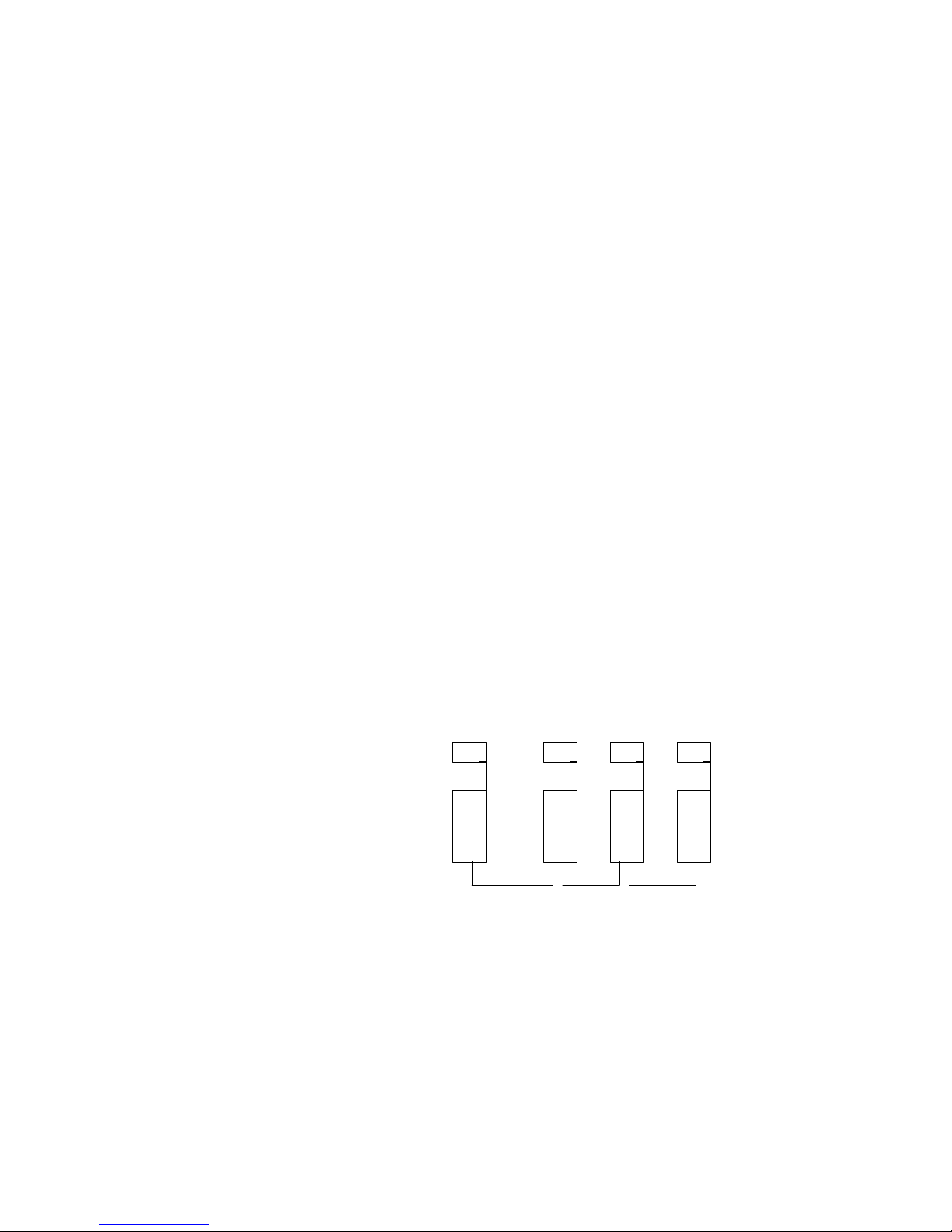
Slave 4 will operate the same patterns as the Master. One Master can control as many slave
heads as you like. Use 3 core microphone cable for short runs and a data cables for longer runs.
On long cable runs a termination resistor may be required on the output of the last scanner.
Pan Reverse (Standalone only)
Changes pan direction on Masters or Slaves. All other movement is synchronised to Master.
Tilt Reverse (Standalone only)
Changes tilt direction on Masters or Slaves. All other movement is synchronised to Master.
DMX Operation
The Defender Range can be operated from Ryger’s own purpose built controller or any DMX
controller. All that is required is to connect the DMX cables and set the DMX base address of
the Defender to a spare set of DMX channels.
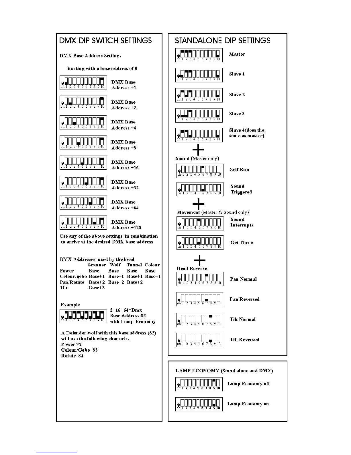
Setting the DMX Base Address
The DMX base address is the first DMX channel that the Defender will use. The Base address
can be set anywhere in the range of 1 to 255. To set the base address set the combination of dip
switches that add up to the base address you require (See Centre Pages). (A dip switch that is
OFF adds no value.)
E.G.To set a base address of 82 you will require to switch dip switches 2,5 & 7 this gives you a
base address of:
Dip switches 1 2 3 4 5 6 7 8
Value 0+2+0+0+16+0+64+0=82
Note: Dip 10 Must always be set to OFF in DMX operation.
DMX Channel allocation
Once the base address is set the features of the Defender heads use the next DMX channels. The
channels that each type of Defender head use and the operation of the channel is listed below
Scanner Wolf/Tunnel Colour
Power Base Address Base Address Base Address
Colour Base Address+1 Base Address+1 BaseAddress+1
Pan/Revolve Base Address+2 Base Address+2
Tilt Base Address+3
Power Operation
Decimal Hex Result
0-127 0-7F Dimmer Off to Full
128-255 80-FF Strobe at full power, 128 Slow to 255 Fast.
Note Always strobes whole gobos.

8
Pan Operation
Decimal Hex Result
0-255 0-FF Full Right to Full Left (Looking at mirror)
Tracks DMX Input.
Tilt Operation
Decimal Hex Result
0-255 0-FF Full Up to Full Down
Tracks DMX input
Colour/Gobo Operation
Decimal Hex Description
00Cyan Bar
12 0c Blue Small Spot
24 18 White Large Spot
36 36 Red Star
48 30 Magenta Squares
60 3c Green Ryger
72 48 Yellow Dots
84 54 Orange Stars
96 60 Green/Orange Spot circle
108 6c Yellow/Blue Circle
In-between these values is a blank, DMX to wheel position is linear from 0-108.
Values greater than 108 will rap around and go back through the gobos
Values greater then 215 will give Cyan/Bar
Rotate Operation
Decimal Hex Result
0-125 0-7D Full Speed to Slow, Clockwise Rotation
126-130 7E-82 Stop
131-255 83-FF Slow Speed to Full, Anti Clockwise Rotation
Lamp Control
The Defender range has a built in dimmer for the lamp. This allows the intensity of the lamp to
be controlled from DMX. Due to the nature of the lamp we don’t recommend that the lamp is
run at very low intensities for long periods as this can dirty the lamp bulb and shorten the lamp
life. The dimmer also provides for a Lamp Economy setting that will increase the lamp life of
the lamp for a small decrease in power output. See General Operation for more details.
Please note
If DMX is selected the lamp will not light until the head has received DMX data to light the
lamp (a power level greater than zero).

9
DMX Wiring
The Controller and heads need to be connected with good quality 3 pin XLR microphone cable
for short runs or a data cables for longer runs. From most DMX desks the DMX is presented on
a 5 pin XLR. To connect the Defenders to this you will need the conversion cable detailed
below. The DMX cabling needs to be ‘daisy chained’ in and out of each unit. At the end of the
DMX run a 100 Ohm termination resistor should be used across the hot (+) and cold (-) pins.
DMX Controller
Out In Out In Out In
DMX Operation
Termination
3 pin XLR to
5 pin XLR wiring
Defender Standard
3 Pin XLR 5 Pin XLR
1 Screen to 1 Screen
2 Hot (+) to 3 Hot (+)
3 Cold (-) to 2 Cold (-)
4 n/c
5 n/c
Notes on DMX Operation
If the DMX controller sends positions to the pan, tilt colour wheels faster than the unit can
move the heads may become temporally out of synchronisation. If this occurs slow down the
pattern or chase speed on the controller until the heads are back working together.

10
Maintenance
Overheating
The Defender contains a thermal cut-out. If the unit overheats the Defender will shut down the
lamp. If this occurs check the ventilation of the unit and the correct operation of the fan. Ensure
that the unit is mounted to allow at least 100mm clearance for vents.
Fuse changing
If the unit stops working check the external fuse . If the fuse has blown It should be replaced
with a 5A fuse. Disconnect the power to the unit before changing the fuse. Ensure that the
fuse holder tightly grips the new fuse.
Lamp Changing
First disconnect the power supply to the unit.
Unscrew the thumb screw at the base of the front panel. Slide out the front panel. Extract the
lamp using the leaver on the base of the lamp holder. Check the lamp holder for wear and
Table of contents