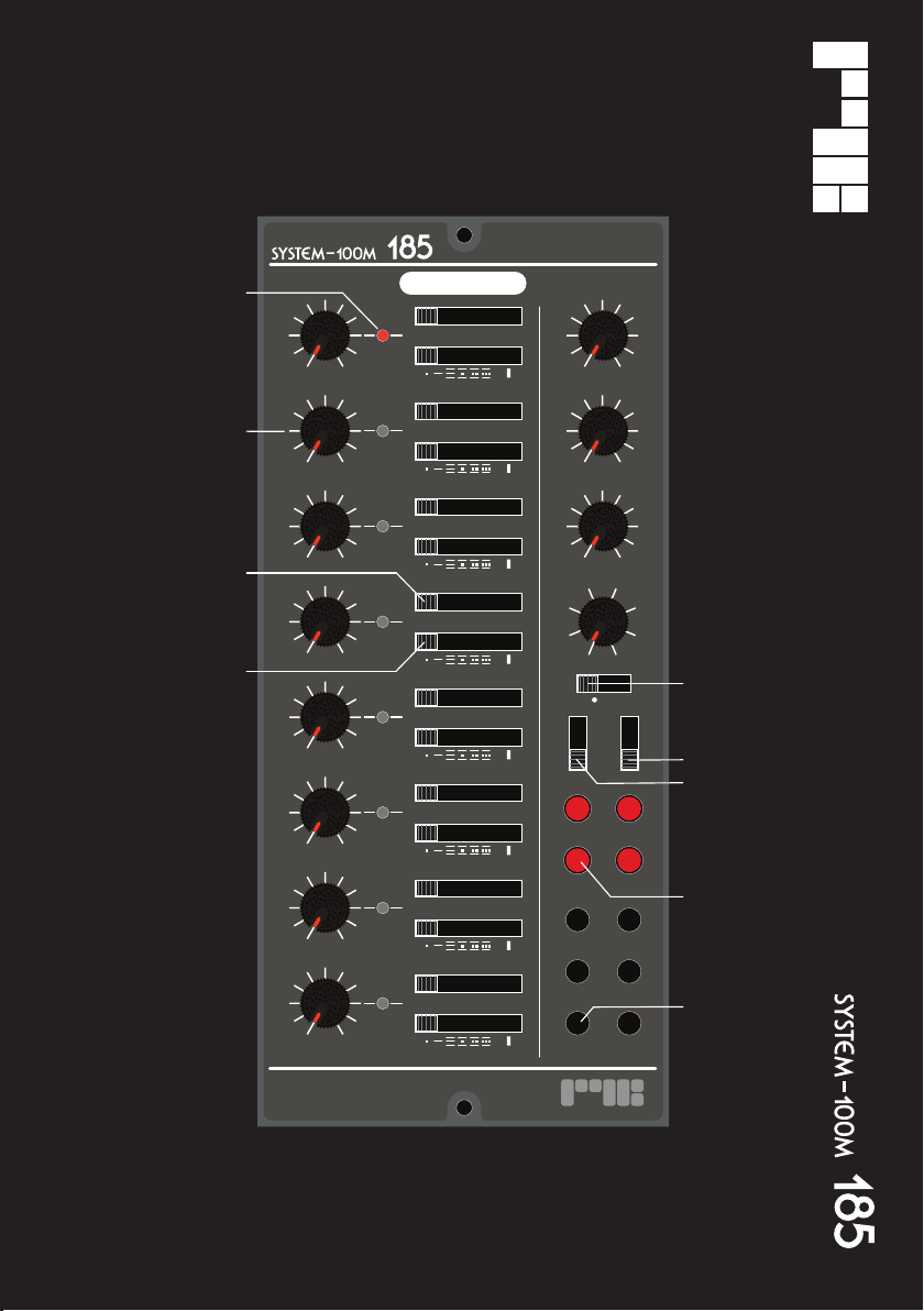
START/ STOP
Press this button to start or stop the internal
sequence clock .
[NB If using an external clock, it is a good idea
to stop the internal clock first ! ]
In the SETTINGS MENUS, the START/STOP
button is used to escape the current menu
level.
RESET
Push this button to reset the sequence to the
first stage.
Press and hold for approx 1 secs, to activate
the SETTINGS MENU.
In a Settings menu, push the RESET button
to toggle a function On/Off or enter a sub
menu.
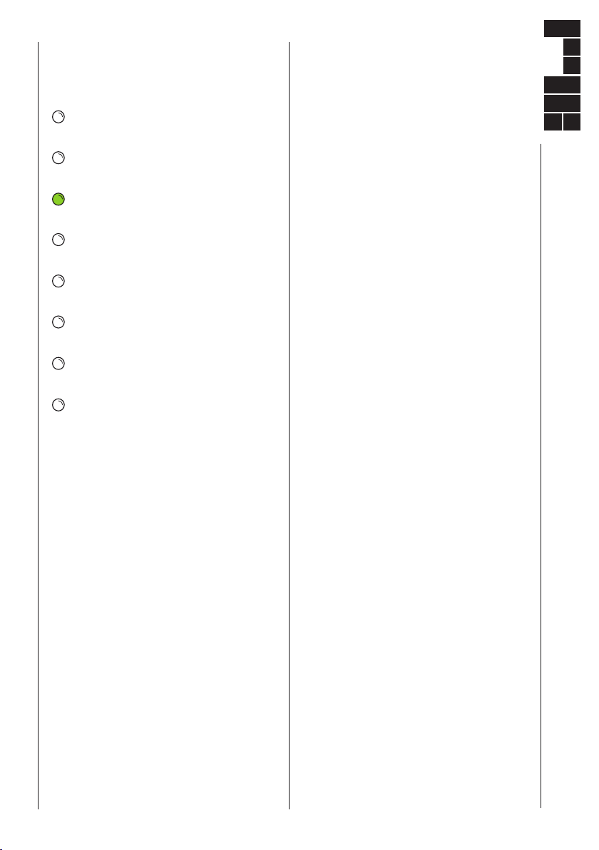
When in GLIDE PROG , push the RESET
button to toggle On/Off the glide setting for
the stage indicated by the flashing Green
LED.
Stages with glide set On, are indicated by a
solid Green LED indicator.
PREV / NEXT
Push to step back or forward through the
Sequence or the Menus.
SEQUENCE MODE
Slide this switch to set the sequence play
mode.
FWD Forward, plays forwards in ascending
order. The sequence will reset after
the last stage set by the Stages-Control.
PNG Ping-Pong, plays forwards, when
reaching the last stage, the direction
reverses and plays back towards the first
stage.
RND Random, plays stages in random
order, from the range of stages set by
the Stages control.
In AB Split Mode, A or B will be choosen
randomly to play in Forward mode.
When in A
B Split Mode, the sequencer will
randomly choose stages from sequence A,
whilst sequence B plays in Forward mode.
FXD: Fixed Length, play forwards, until a
fixed number of clock pulses have elapsed,
before restarting from the first stage.
The sequence length of clock pulses is
determined by the value of the Stages Control
multiplied by 4.
FIXED LENGTH TIP:
Set the STAGES to “4”; the sequencer will
play 16 clock pulses of the sequence before
resetting.
The sequence length is not afftected by the
total value of the Stage Counts.
This mode is great for locking a sequence to a
drum-machine for repeating groove type
sequences.
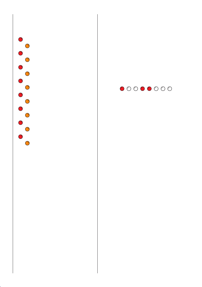
SPLIT MODE
Slide this switch to select and set the Split
Mode settings.
OFF No Split, plays without any split.
AB Serial Split Mode, plays Sequence A
“X” times, then plays Sequence B “Y”
times.
A
BParallel Split Mode, simultaniously
plays Sequence A and Sequence B.
Sequence A CV/GATE are ouput to CH1 and
MIDI Note output.
Sequence B CV/GATE are output to CH2.
SET Enables setting the split point, and
repeat counts for A and B Sequences.
To setup a sequence split, use the
PREV/NEXT controls to move the Green LED
cursor to define the Split point [ start of
Sequence B ], then press RESET to set the
point.
Next, use the PREV/NEXT controls to move
the Green LED cursor to define the repeat
count of Sequence A, then push RESET to
set.
Finally, use the PREV/NEXT controls to move
the Green LED cursor to define the repeat
count of Sequence B, then push RESET to
set.
Once this is complete, move the switch to
select AB serial split, or A
B parallel split.
2