RYNO WORX AirBoss 300-V2 User manual

AirBoss 300-V2
Operator's Manual
RA-SSY-0027
RA-SSY-0028
RC-SUM-0014 - Rev 2
RA-SSY-0030
*RA-SSY-0030 Pictured Above

RA-SSY-0028
RA-SSY-0027

1SAFETY & GENERAL INFORMATION
Warnings
⚠Failure to follow all safety precautions can result in serious injury or death
⚠RynoWorx Inc. assumes no liability for any accident or injury incurred through improper use of machine
⚠CHECK ENGINE, COMPRESSOR, AND HYDRAULIC OIL LEVELS BEFORE FIRST USE
⚠Read all instructions and warnings in this manual as well as the engine manufacturer's manual before
operating this equipment
⚠Verify all seals and clamps for all connections are tightened before each use of this equipment
⚠This equipment is designed for outdoor use only
⚠Be sure to always wear personal protective equipment when operating this equipment. Eyes, Gloves,
Hearing, Boots, Long Pant, Long Sleeves, etc…
⚠Carefully read all Material Safety Data Sheets (SDS) for sealer products being used before operating this
equipment. Refined coal tar, and Asphalt Emulsion sealers can cause health risks if not properly handled
⚠Only genuine replacement parts should be used for any replacements or repairs. Do not attempt to modify
or alter this product in any way
⚠Observe all caution and warning signs on machine
⚠Do not leave unattended when running
⚠Never point the spray wand at another person
⚠Keep all body parts out of lid opening when the unit is running
⚠Keep hands and arms clear while opening and closing the lid
⚠Keep the tank lid closed during operation
⚠Do not let any sealer freeze or dry inside the unit’s plumbing
⚠Never enter the tank with sealer inside
⚠Always drain the tank and let any residual sealer dry before entering the tank
⚠Replace any hoses that show wear, fraying or splits. Be sure all joints are leak-proof
⚠Shut down and allow compressor engine to cool prior to refilling the gas tank
⚠Never operate near an open flame or use any type of flame to unclog the plumbing
⚠Check all operation manuals for warnings, cautions and to ensure proper maintenance procedures are
followed
⚠Always turn the gas off on the engine before transporting
⚠Only stainless-steel thread seal tape should be used, on the diaphragm pump
plumbing components, as the parts are aluminum and stainless steel. Regular Teflon
based thread seal tape will not work as well

Factory Calibrations:
Your AirBoss was calibrated using:
•2.0 GPM tips with water
•50 psi in the expansion tank
•regulator set to 90psi
Your AirBoss was factory tested for several hours, and calibrated to meet the following performance
specifications:
•Engine kick-up RPM: <TBD>
•Engine Kick-down RPM: <TBD>
•Fill from 0 –115 psi: <TBD>
•Duty cycle with 2GPM tip (spraying): <TBD>
•PSI at the spray wand: <TBD>
•Compressor CFM: <TBD>
•Kick-down psi: <TBD>
•Kick-up psi: <TBD>
Technical Specifications:
RA-SSY-0027
(Entry)
RA-SSY-0028
(Standard)
RA-SSY-0030
(Pro)
Airline Water Filter
Yes
Yes
Yes
Compressor Oil Capacity (US qt / L)
0.26 / 0.25
0.26 / 0.25
0.26 / 0.25
Compressor Oil Grade (Conventional)
20 Weight
20 Weight
20 Weight
Compressor Oil Grade (Synthetic)
ISO 46
ISO 46
ISO 46
Compressor Pump CFM
12
12
12
Compressor Pump Psi (Working / Max)
90 / 120
90 / 120
90 / 120
Compressor Tank Capacity (US gal / L)
9 / 34
9 / 34
9 / 34
Engine Displacement (cu. in. / cc)
12 / 196
12 / 196
16.9 / 277
Engine Oil Capacity (US qt / L)
0.63 / 0.6
0.63 / 0.6
1.16 / 1.1
Engine Oil Grade (Conventional)
5W30 or 10W30
5W30 or 10W30
5W30 or 10W30
Engine Oil Grade (Synthetic)
5W50 or 10W50
5W50 or 10W50
5W50 or 10W50
Engine Power (HP / KW)
6.5 / 4.8
6.5 / 4.8
9.5 / 7.1
Engine Torque (Ft lbs/Nm)
10.2 / 13.9
10.2 / 13.9
13.9 / 18.8
Expansion tank –psi
See Chart
See Chart
See Chart
Fuel Tank Capacity (US qt / L)
3.3 / 3.4
3.3 / 3.4
7.2 / 6.8
Hydraulic Oil Capacity
N/A
N/A
5 Gallons
Hydraulic Oil Grade
ISO 46 or ISO 68
ISO 46 or ISO 68
ISO 46 or ISO 68
Spark plug gap (in / mm)
0.030 / 0.76
0.030 / 0.76
0.030 / 0.76
Tank Capacity
304 US Gallons
304 US Gallons
304 US Gallons
Weight –Empty Tank
1150 Lbs
1250 Lbs
1450 Lbs
Weight –Filled Tank * Approx
4150 Lbs
4250 Lbs
4450 Lbs

Required Tools
Your AirBoss spray system should arrive completely assembled. No tools are required to begin operation.
Suggested tools to have on hand:
•12" Pipe Wrench (with 2.5" Jaw)
•Adjustable wrench (1.5”width) or Channel Lock pliers
•Ratchet set
•Allen Key Set
•Screwdriver Set
•Stainless steel thread tape
•Power Drill
•Drum or tote mixer
•5 gallons of clean water for priming and cleaning (not including what you need to mix with your sealer)
Compressor Details
MAINTENANCE SCHEDULE
Check oil levels:
Compressor oil should be level with the red dot at the center of the sight glass shown above.
Compressor Oil Capacity: 0.26 qt / 0.25 L
20 weight compressor oil
Or
ISO 46 or 68 synthetic compressor oil
Oil Sight Glass

Engine Details
The Entry & Standard AirBoss systems are equipped with a Kohler SH265 engine
The Pro AirBoss system is equipped with a Kohler CH395 engine
REPAIRS/SERVICE PARTS
Kohler genuine service parts can be purchased from Kohler authorized dealers. To find a local Kohler
authorized dealer visit KohlerEngines.com or call 1-800-544-2444 (U.S. and Canada).
OIL RECOMMENDATIONS
All-season KOHLER® PRO 10W-50 Synthetic Oil is the ideal oil for KOHLER engines. It is specifically
formulated to extend the oil change interval to 300 Hours. Contact your Kohler authorized dealer for
availability. 300-Hour oil change intervals are exclusive to and only authorized on KOHLER engines that utilize
the KOHLER PRO 10W-50 Synthetic Oil. Alternative engine oils may be used with KOHLER engines but require
100-Hour oil change intervals for proper maintenance. Oil must be API (American Petroleum Institute) service
class SJ or higher. Select viscosity based on air temperature at time of operation as shown below.
FUEL RECOMMENDATIONS
⚠WARNING
●Explosive Fuel can cause fires and severe burns.
●Do not fill fuel tank while engine is hot or running.
●Gasoline is extremely flammable, and the vapors can explode if ignited. Store gasoline only in approved
containers, in well ventilated, unoccupied buildings, away from sparks or flames. Spilled fuel could ignite if it
encounters hot parts or sparks from ignition. Never use gasoline as a cleaning agent.
NOTE: E15, E20 and E85 are NOT approved and should NOT be used; effects of old, stale, or contaminated fuel
are not warrantable.
Fuel must meet these requirements:
●Clean, fresh, unleaded gasoline.
●Octane rating of 87 (R+M)/2 or higher.
●Research Octane Number (RON) 90 octane minimum.
●Gasoline up to 10% ethyl alcohol, 90% unleaded is acceptable.
●Methyl Tertiary Butyl Ether (MTBE) and unleaded gasoline blend (max 15% MTBE by volume) are
approved.
●do not add oil to gasoline.
●do not overfill fuel tank.
●do not use gasoline older than 30 days.

2PART DIAGRAMS
Merge PDF part diagrams

3OPERATION
3.1 Operation Guidelines
•The AirBoss system was pre-tested for leaks before shipping, however, we recommend that you test
the system using WATER to ensure you do not have leaks before moving onto sealant
•The air-pump is self-priming
•Flush clean water through the pump and hoses at the end of each day
•Place any used spray tips into a soapy water solution at the end of each day
•Do not let sealant dry onto the spray tips
•Clean the spray tips with soft nylon brushes only
•Have clean water available at the job site for emergency rinsing
•Clean the strainer daily to ensure proper sealant flow
•Check the engine oil levels daily
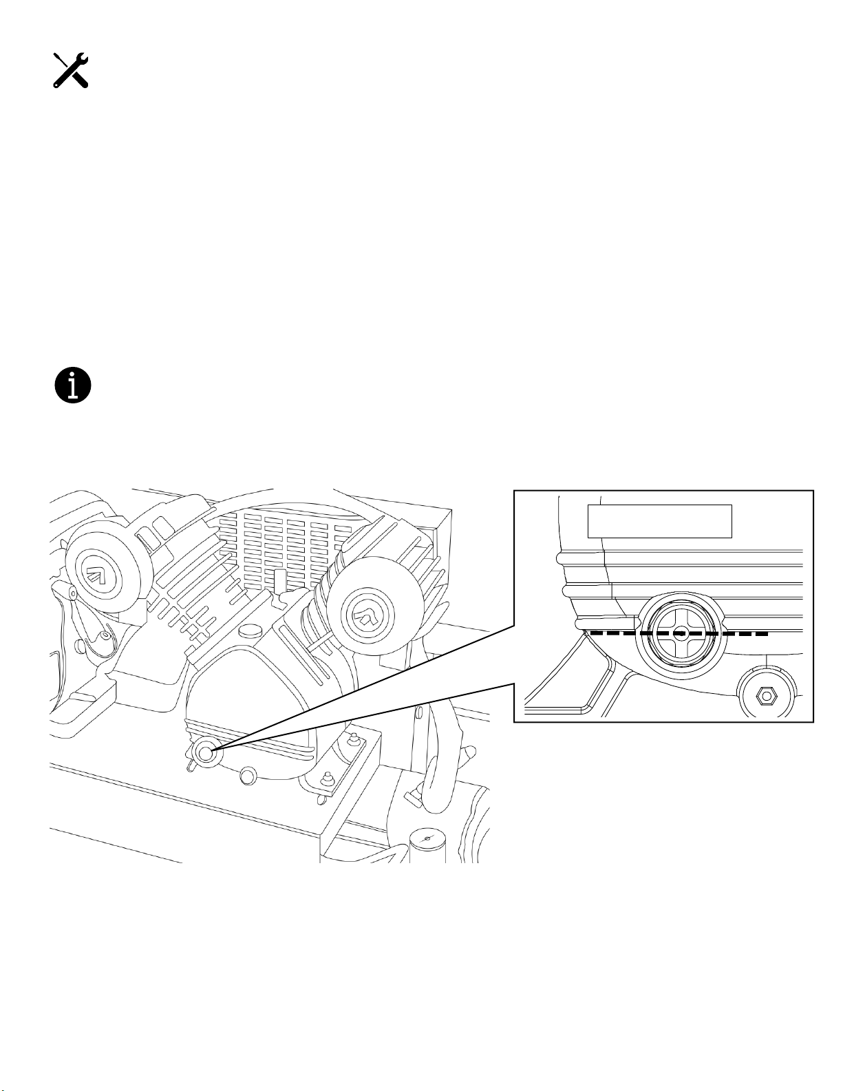
•Check the compressor oil levels daily
•Check the hydraulic oil levels daily *if equipped
•Check the airline oiler oil levels daily *if equipped
⚠WARNING
●Turn the engine off for extended work stoppages (10+ minutes), such as breaks, lunches, or other unplanned
work stoppages
●avoid recirculating for more than 10 minutes at a time
NOTE: Apart from wasting fuel, this may cause your sealant to become foamy, which can introduce excessive
air into the lines and can cause inconsistent spray intensity.
●Foamy sealant can take an hour or more to return to a useable state.
●Set fuel control to OFF while traveling (if equipped)
Spray Tips
Each system ships with 4 sizes of spray tips (80/30, 80/40, 80/50, 80/70). The spray wand (RA-SWA-0005)
included with your AirBoss will have an 80/20 tip installed on it for a total of FIVE tips.
The 80/20 tip is what all our benchmarks were completed with (see the specifications chart for details). The 2
numbers are used to designate the spray tip size denote the spray fan angle and tip flow when sprayed at 40
psi (for example, an 80/20 has an 80° spray fan angle and has approximately 2.0 GPM of flow when sprayed at
40 psi). Increasing or decreasing the regulator pressure will also increase or decrease the tip flow rate from
the 40 psi rating.
Tip sizes like an 80/20 or 80/30 are ideal for smaller jobs, like driveways, while larger tips are more suitable for
large driveways and parking lots. You will also need to consider the type of product you are working with.
Coal tar products have less solids in them and should work trouble free with any of the included sizes.
Emulsion based sealers have more solids in them, and will likely require 80/50 tips or larger to work effectively.

Filter baskets
Your system comes with 2 sizes of filter baskets. 4 mm (approx. 5/32”) and 5.5 mm (approx. 7/32”). We
recommend using the larger basket for emulsion and sealers with more solid, and the smaller filter for coal tar
sealers.
If you find that you are getting a lot of clogs in your spray tips, we suggest:
•Recirculating more to get a more uniform consistency
•Adding more water and recirculate
•Changing to a large spray tip size
•Using the smaller filter basket and cleaning it more often

3.2 Compressor Operation
Auto Idle Throttle Control Cable (kick-down)
Your AirBoss Spray system is equipped with an auto idle kickdown to lower engine RPM when the compressor
tanks are full. This cable runs from the brass valve to the throttle on your engine.
This sensor is attached between the compressor and the tank and will reduce the engine RPM when the target
PSI has been achieved.

Compressor & Air Tanks:
NOTE: You must fully open the pressure relief valves at the bottom of BOTH tanks at the end of each day.
Condensation and sediment can form and shorten the life of the tanks.

Setting the desired pressure:
1. Gauge that displays the current pressure in the tanks
2. Regulator valve to adjust desired operating air pressure
•Clockwise to increase pressure, counter-clockwise to decrease
•Push to lock, pull to unlock
3. Gauge that displays the operating air pressure
Note: the regulator will be set to 90 psi from the factory on all AirBoss 300 models
3
2
1
+
-

Expansion tank:
Your AirBoss is equipped with an expansion tank that helps to minimize pulses created by the diaphragm
pump. This expansion tank has a bladder inside that can be charges with air to help dial in the perfect amount
a dampening.
The expansion tank is pre-charged with 50psi from the factory. You may find that you prefer increasing or
decreasing this amount if you are operating a very high or very log pressures from your AirBoss. 50psi was
found to be a sweet spot that covers most of the typical operating pressures you will encounter.
The valve is a Shrader style valve –the same as equipped on all cars and trucks. It can be accessed by
unscrewing the plastic cover on the top of the tank.

Airline Valve:
The AirBoss unit is equipped with a ball valve to control the air flow to the diaphragm pump. This valve should
be closed when not in use, and open during all operations.
THE PUMP CANNOT WORK WITH THE VALVE CLOSED.
CLOSED OPEN

Water Separator:
There is also a water separator attached to this valve. During normal operation, water will collect in the
reservoir and will need to be emptied. It can be emptied by pushing upwards on the bottom of the vial.

3.3 System Modes
Agitation: Entry / Standard System
Notes:
•we suggest that you turn the agitation handle a few times hourly to prevent aggregate from settling
•Agitation handle is approximately 3:1 (3 turns of handle = 1 turn inside tank)
•After work stoppages of more than 30 minutes, we recommend recirculating for 2-3 minute before
resuming work
Agitation: Pro System
Forward Off Reverse
Always turn the
agitation handle
counter-clockwise

Input Modes
1) Main 300-gallon Tank
This is going to be the way you will be operating most of the time. Feeding from your main 300-gallon tank.
•Close the 1.5” valve at the front/top of the unit (connected to the filter pot)
•Open the 2” valve at the front/bottom of the unit (connected to the tank)
2) Secondary Input Source/ Transfer
This is primarily going to be for re-filling your 300-gallon tank from a 2ndary source, such as a barrel or tote
However, this secondary source can also be used for general spraying as well (spraying directly from a tote or
barrel)
•Open the 1.5” valve at the front/top of the unit (connected to the filter pot)
•Close the 2” valve at the front/bottom of the unit (connected to the tank)

Output Modes
1) Recirculation Mode
This is one of 2 ways that you can mix your product. This will output back into the 300-gallon tank to help mix
your product before beginning work
•Close the 1.5” valve at the front/top of the unit (connected to the filter pot)
•Open the 2” valve at the front/bottom of the unit (connected to the tank)
•Open the 1.5”valve at the back/top of the unit (connected to the pump)
•Close the ¾” valve at the back/top of the unit (connected to the pump)

2) Spray Mode
This is how you will be operating your system most of the time. Spraying through your spray wand.
•Close the 1.5” valve at the front/top of the unit (connected to the filter pot)
•Open the 2” valve at the front/bottom of the unit (connected to the tank)
•Close the 1.5”valve at the back/top of the unit (connected to the pump)
•Open the ¾” valve at the back/top of the unit (connected to the pump)

Travel Mode
Make sure to secure the pins on the manway as well as the pin on the agitation handle before transporting the
unit.
In order to reduce any risks of spillage while traveling, we recommend that you close ALL FOUR valves
whenever traveling with the unit.
•Close the 1.5” valve at the front/top of the unit (connected to the filter pot)
•Close the 2” valve at the front/bottom of the unit (connected to the tank)
•Close the 1.5” valve at the back/top of the unit (connected to the pump)
•Close the ¾” valve at the back/top of the unit (connected to the pump)
This manual suits for next models
3
Table of contents
Other RYNO WORX Paint Sprayer manuals