Larius Pegaso Manual

ENGLISH
MAINTENANCE INSTRUCTION
OPERATING AND
OPERATING AND


1
PEGASO
English
APPARATUS FOR SPRAYING
INTERIOR FINISHING LAYERS
APPARATUS FOR SPRAYING
INTERIOR FINISHING LAYERS
WE ADVISE THE USE OF THIS EQUIPMENT ONLY BY PROFESSIONAL OPERATORS.
ONLY USE THIS MACHINE FOR USAGE SPECIFICALLY MENTIONED IN THIS MANUAL.
Thank you for choosing a LARIUS S.R.L. product.
As well as the product purchased,
you will receive a range of support services
enabling you to achieve the results desired,
quickly and professionally.
It indicates an
accident risk or
serious damage to
equipment if this
warning is
not followed.
It indicates a fire
or explosion risk if
this warning is not
followed.
It is obligatory to wear suitable clothing as gloves,
goggles and face shield.
Read this operator’s
manual carefully
before using the
equipment. An
improper use of this
machine can cause
injuries to people or
things.
It indicates important
recommendations
about disposal
andrecycling
process of products
in accordance with
the environmental
regulations.
A
B
C
D
E
F
G
H
P
Q
R
S
T
O
U
V
Y
I
LX
M
N
W
Z
STARTING THE SPRAYING OPERATIONS....... p.14
REGULATIONS ..................................................p.15
CLEANING AT THE END OF THE WORK .........p.16
PROCEDURE OF DECOMPRESSION.............. p.18
MOVING THE SPRAYER ................................... p.18
ROUTINE MAINTENANCE ................................p.19
PROCEDURE FOR REPLACING THE HOSE ... p.20
CLEANING AND REPLACING
THE SENSOR CLEANING.................................p.23
PROBLEMS AND SOLUTIONS .........................p.24
SPARE PARTS ..................................................p.26
ACCESSORIES..................................................p.38
AIR DIAGRAM.................................................... p.40
WIRING SYSTEM .............................................. p.41
INTRODUCTION ...........................................................p.1
WORKING PRINCIPLE ......................................p.2
TECHNICAL DATA.............................................. p.2
DESCRIPTION OF THE EQUIPMENT............... p.4
TRANSPORT AND UNPACKING .......................p.6
SAFETY RULES.................................................p.6
SETTING-UP......................................................p.8
SETUP................................................................ p.9
POSITION AND INSTALLATION
OF THE TANK..................................................... p.10
CONTROLS........................................................ p.11
STARTUP ........................................................... p.12
WASHING OF THE NEW EQUIPMENT............. p.13
MIXING MATERIAL ............................................ p.13

2
PEGASO
English
TECHNICAL DATA
POWER SUPPLY standard
to request
POWER CABLE
MAXIMUM WORKING FLUID PRESSURE
MAXIMUM WORKING AIR PRESSURE
COMPRESSOR SPECIFICATIONS
Air delivery
Power
PUMP SPECIFICATIONS
Flow rate litres/hours
Feed hose (lLength depending on the material)
Power
PRESSURE SWITCH 24 Vdc
HOPPER CAPACITY
MAXIMUM DELIVER WITH MATERIAL
WETTED PARTS
SOUND PRESSURE LEVEL
DIMENSIONS
ALenght
BWidth
CTotal height
DProduct load height
POIDS with hoses and gun
230 V - 50 Hz
110 V - 60 Hz
mt 5 - c 3x2,5
MAX. 10 bar
MAX. 7 bar
283 l/min
1,5 kw
144
MIN. 7mt - MAX. 30 mt
0,18 kw
4,00 mA - 0-20 bar
50 litres
7 l/minute
PVC, anodized aluminum - inox
MAX. 70 db (A)
980
730
1050
900
110 Kg
A
B
FOR WATER-BASED MATERIALS ONLY
WORKING PRINCIPLE
The PEGASO apparatus is an electric pump, used for
spraying wall plaster or synthetic materials for covering
indoor and outdoor walls.
The apparatus is equipped with a 50 litre tank, easy to fill
and funnel-shaped, which makes it easy for the material
to fall into the peristaltic pump.
The pump, easy to maintain, allows for a regular and
constant flow of the product.
On the end of the feed pipe there is a maximum pressure
valve, in order to eliminate choking or occlusions that can
damage the pipe.
When the operator squeezes the trigger on the gun, the
flow and pressure of the pump start, creating a soft flow
of material. When the trigger is released, the flow stops.
The supply of vaporisation air only occurs if the trigger is
squeezed.

3
PEGASO
English
(A) 890
500
Ø=300
(C) 1050
(D) 900
55
(B) 730

4
PEGASO
English
14
3
1
5
4
6
7
12
8
13
9
10
11
2
15
16
17
18

5
PEGASO
English
COMPONENTS DESCRIPTION
C
POS.
1
2
3
4
5
6
7
8
9
10
11
12
13
14
15
16
17
COMPONENTS DESCRIPTION SEE TABLE
☞PLEASE NOTE :
All red coloured component support assembled groups that are easy to disassemble.
18 Machine nameplate and name of the manufacturer
PLEASE NOTE:
To be sure about the perfect working of all mechani-
cal parts, use only original spare parts. In case of order of spare parts
or for any information about orders it is always necessary to specify:
- Type of models
- Serial number
- Production year
Frame
Tank 50 L
Group of control
Pump
Compressor
Support pressure
Pressure sensor
Reservoir air
High pressure Gun
Air hose
Air material
Recirculation tube
Wheel
Cover
Power Cord
Re-circulation tap
Material passage tap
TABLE 01 - page 27
TABLE 02 - page 28
TABLE 03 - page 29
TABLE 06 - page 32
TABLE 04 - page 30
TABLE 06 - page 32
TABLE 06 - page 32
TABLE 08 - page 35
TABLES 09/10 - pages 36-37
-
-
TABLE 06 - page 32
TABLE 01 - page 27
TABLE 01 - page 27
TABLE 01 - page 27
TABLE 06 - page 32
TABLE 06 - page 32

6
PEGASO
English
D
E
TRANSPORT
AND UNPACKING
• The packed parts should be handled as indicated
in the symbols and markings on the outside of the
packing.
• Beforeinstallingtheequipment,ensurethattheareato
be used is large enough for such purposes, is properly
lit and has a clean, smooth floor surface.
• Theuserisresponsiblefortheoperationsofunloading
and handling and should use the maximum care so as
not to damage the individual parts or injure anyone.
To perform the unloading operation, use only qualified
and trained personnel (truck and crane operators, etc.)
and also suitable hoisting equipment for the weight of
the installation or its parts.
Follow carefully all the safety rules.
The personnel must be equipped with the necessary
safety clothing.
• Ringboltattachmentshavebeeninstalledforliftingthe
machine. Lift the machine as indicated in the drawing.
SAFETY RULES
•THE EMPLOYER SHALL TRAIN ITS EMPLOYEES
ABOUT ALL THOSE RISKS STEMMING FROM ACCI-
DENTS, ABOUTTHE USE OF SAFETY DEVICES FOR
THEIR OWN SAFETY AND ABOUT THE GENERAL
RULES FOR ACCIDENT PREVENTION IN COMPLIAN-
CEWITH INTERNATIONAL REGULATIONS ANDWITH
THE LAWS OF THE COUNTRY WHERE THE PLANT
IS USED.
•THE BEHAVIOUR OF THE EMPLOYEES SHALL
STRICTLY COMPLY WITH THE ACCIDENT PREVEN-
TION AND ALSO ENVIRONMENTAL REGULATIONS
IN FORCE IN THE COUNTRY WHERE THE PLANT
IS INSTALLED AND USED.
Read carefully and entirely the following
instructions before using the product. Please
save these instructions in a safe place.
The unauthorised tampering/replacement of
one or more parts composing the machine, the
use of accessories,tools,expendable materials
other than those recommended by the manu-
facturer can be a danger of accident.
The manufacturer will be relieved from tort and
criminal liability.
•KEEPYOUR WORK PLACE CLEAN AND TIDY. DISORDER
WHERE YOU ARE WORKING CREATES A POTENTIAL
RISK OF ACCIDENTS.
•ALWAYS KEEP PROPER BALANCE AVOIDING UNUSUAL
STANCE.
• The manufacturer will not be responsible for the
unloading operations and transport to the workplace
of the machine.
• Check the packing is undamaged on receipt of the
equipment. Unpack the machine and verify if there
has been any damage due to transportation.
In case of damage, call immediately LARIUS and the
Shipping Agent.All the notices about possible damage
or anomalies must arrive timely within 8 days at least
from the date of receipt of the plant through Registered
Letter to the Shipping Agent and to LARIUS.
• Thedisposalofpackagingmaterialsisacustomer’s
competenceand must be performedin accordance with
the regulations in force in the country where the plant is
installed and used.It is nevertheless sound practice to
recycle packaging materials in an environment-friendly
manner as much as possible.

7
PEGASO
English
•BEFORE USING THE TOOL, ENSURE THERE ARE NOT
DAMAGED PARTS AND THE MACHINE CAN WORK PRO-
PERLY.
•ALWAYS FOLLOW THE INSTRUCTIONS ABOUT SAFETY
AND THE REGULATIONS IN FORCE.
•KEEP THOSE WHO ARE NOT RESPONSIBLE FOR THE
EQUIPMENT OUT OF THE WORK AREA.
•NEVER EXCEED THE MAXIMUM WORKING PRESSURE
INDICATED.
•NEVER POINT THE SPRAY GUN AT YOURSELVES OR AT
OTHER PEOPLE.THE CONTACTWITHTHE CASTING CAN
CAUSE SERIOUS INJURIES.
•IN CASE OF INJURIES CAUSED BY THE GUN CASTING,
SEEK IMMEDIATE MEDICAL ADVICE SPECIFYING THE
TYPE OF THE PRODUCT INJECTED. NEVER UNDER-
VALUE A WOUND CAUSED BY THE INJECTION OF A
FLUID.
•ALWAYS DISCONNECTTHE SUPPLY AND RELEASE THE
PRESSURE INTHE CIRCUIT BEFORE PERFORMING ANY
CHECK OR PART REPLACEMENT OF THE EQUIPMENT.
•NEVER MODIFY ANY PART IN THE EQUIPMENT. CHECK
REGULARLY THE COMPONENTS OF THE SYSTEM.
REPLACE THE PARTS DAMAGED OR WORN.
•TIGHTEN AND CHECK ALLTHE FITTINGS FOR CONNEC-
TION BETWEEN PUMP, FLEXIBLE HOSE AND SPRAY GUN
BEFORE USING THE EQUIPMENT.
•ALWAYS USE THE FLEXIBLE HOSE SUPPLIED WITH
STANDARD KIT. THE USE OF ANY ACCESSORIES OR
TOOLING OTHER THAN THOSE RECOMMENDED IN
THIS MANUAL, MAY CAUSE DAMAGE OR INJURE THE
OPERATOR.
•THE FLUID CONTAINED IN THE FLEXIBLE HOSE CAN
BE VERY DANGEROUS. HANDLE THE FLEXIBLE HOSE
CAREFULLY. DO NOT PULL THE FLEXIBLE HOSE TO
MOVE THE EQUIPMENT. NEVER USE A DAMAGED OR
A REPAIRED FLEXIBLE HOSE.
The high speed of travel of the product in
the hose can create static electricity through
discharges and sparks. It is suggested to earth
the equipment. The pump is earthed through
the earth cable of the supply.
The gun is earthed through the high pressure
flexible hose.
All the conductors near the work area must
be earthed.
•NEVER SPRAY OVER FLAMMABLE PRODUCTS OR
SOLVENTS IN CLOSED PLACES.
•NEVER USE THE TOOLING IN PRESENCE OF POTEN-
TIALLY EXPLOSIVE GAS.
Always check the product is compatible with the materials
composing the equipment (pump, spray gun, flexible hose
and accessories) with which it can come into contact. Never
use paints or solvents containing halogen hydrocarbons (as
the methylene chloride).
If these products come into contact with aluminium parts can
provoke dangerous chemical reactions with risk of corrosion
and explosion.
IF THE PRODUCT TO BE USED IS TOXIC, AVOID INHALA-
TION AND CONTACT BY USING PROTECTION GLOVES,
GOGGLES AND PROPER FACE SHIELDS.
TAKE PROPER SAFETY MEASURES FOR THE PRO-
TECTION OF HEARING IN CASE OF WORK NEAR THE
PLANT.
Electrical safety precautions
• Checktheswitchisonthe"OFF"positionbeforeconnecting
the cable to the mains.
• Nevercarryaplugged-inequipment.
• Disconnect the equipment before storing it and before
performing any maintenance operation or replacing of ac-
cessories.
• Donotcarrytheequipmentneitherunplugitbypullingthe
electric cable. Protect the cable from heat, oil and sharp
edges.
• Whenthetoolisusedoutdoors,useonlyanextensioncable
suited for outdoor use and so marked.
Never attempt to tamper with the calibre of
instruments.
• Takecarewhenthepumpingrodismoving.
Stop the machine whenever someone is within its vicinity.
• Repairsoftheelectricalequipmentshouldonlybecarried
out by skilled personnel, otherwise considerabledanger to
the user may result.
8
PEGASO
English
SETTING-UP
CONNECTION OF THE FLEXIBLE HOSE TO THE GUN
• Connectthepressureflexiblehosetothepumpand
the gun tightening the metal clamps.
NEVER use sealants on fittings threads.
The type of materiel you are spraying
will determine the maximum lenght of
hoseyou can use. If you are not achieving
a satisfactory spray pattern or coverage,
try using a shirter lenght of hose.
• Itisrecommendedtousethehoseprovidedwiththe
standard kit. NEVER use a damaged or a repaired
flexible hose.
CHECK ON POWER SUPPLY
• Check the plant is earthed.
• Check the mains voltage corresponds to the equip-
ment’s rating.
• The supply cable is provided without plug. Use a plug
which guarantees the plant earthing. Only a technician
or a skilled person should perform the connection of
the plug to the electric cable.
Should anyone use an extension cable between the
tooling and the socket, it must have the same cha-
racteristics as the cable supplied (minimum diame-
ter of the wire 2.5 mm2) with a maximum length of
50 mt. Higher lengths and lower diameters can pro-
voke excessive voltage falls and also an anomalous
working of the equipment.
☞PLEASE NOTE :
Check the ON/OFF switch is on the “OFF” position
(0) before connecting the cable to the mains.
F

9
PEGASO
English
GSETUP
• Connectoneendofairhosetosprayerairoutletquick
connect and to gun air inlet quick connect (G1).
• Connectoneendofmaterialhosetomaterialoutlet
and the other end to gun material inlet (G2). Firmly
tighten the metal clamps.
• Installspraynozzle(G3). See selection chart page 12.
Pulling trigger when installing nozzles, eases assembly
(G4).
• Plugpowercordintoproperlygroundedoutlet.
☞PLEASE NOTE :
Check the ON/OFF switch is on the “OFF” position
(0)before connecting the cable to the mains.
G
G1
G2
G3
G4

10
PEGASO
English
POSITION AND INSTALLATION
OF THE TANK
• The 50 litre tank can be disassembled and easily
cleaned.
• Unscrew the bolts and insert/disengage the basket
supporting the tank from the machine body, or lift the
tank to remove it from its support.
• Connect / disconnect the suction hose by opening
the rapid coupling (H1) that permits the operations
of filling / emptying the tank.
• The tank is equipped with a cover that can easily
be removed in order make inspection and cleaning
operations easier.
H
H1

11
PEGASO
English
I
6
1
4
3
5
2
7
8
9
CONTROLS
1) Sprayer starter switch
- In the “0” position the machine is not powered
- In the “1” position the machine is powered
2) Emergency cut-out, making it possible to discon-
nect power from the machine. Press in case of
emergency.
3) Pump starter switch.
- In the “OFF” position the pump is off
- In the “ON” position the pump is on
4) Compressor starter switch.
- In the “OFF” position the compressor is off
- In the “ON” position the compressor is on
5) Potentiometer, rotate clockwise to increase the flow
of product.
6) Display, pump pressure reading LED.
7) Power supply socket (220 V) for attaching supple-
mentary apparatus (such as a drill).
8) Regulator with pressure gauge for adjusting the air
flow.
9) Rotation control selector switch for the peristaltic
pump. Three-position selector with return to the
centre from left and fixed to the right.
- Turn counter-clockwise and hold in position to invert
pump function;
- Turn clockwise (fixed position) for normal functioning
mode of the pump;
- In the central position, the pump remains inactive.

12
PEGASO
English
L
L4
L3
6
4
8
10
12
2
0
STARTUP
STARTING THE SYSTEM MAIN METHOD
WITH AIR FLOW
• TurnsprayermainpowerON.
• Startthepump.
• Turn the “Pump Rotation” selector clockwise.
•Start the compressor.
•Close the recycle valve (L3).
•Open the air valve (L1) on the regulator and on the
gun (L2).
• Aim gun hopper and slightly press gun riger. This
automatically delivers material pressure and flow.
ALTERNATIVE METHOD WITHOUT AIR FLOW
• TurnsprayermainpowerON.
• Reduce fluid flow pressure to the minimum (turn
counterclockwise the pressure control knob).
• Insertthepumpswitch.
• Turnthe“PumpRotation”selectorclockwise.
• Closetherecyclevalve(L3).
Aim gun into hopper and squeeze gun riger.
Excessive or prolonged use of Prime
Switch can causa to back up into gun air
passages, causing blockage and/or gun air
valve failure.
ALTERNATIVE METHOD WITH RE-CIRCULATION
• TurnsprayermainpowerON.
• Turnfluidflowregulatorupasnecessary.
• Opentherecirculatingvalve (L3).
• Close the material passage valve (L4) on the gun.
• Turnthepumpstarterswitchto“ON”.
• Turnthe“PumpRotation”selectorclockwise.
• Waitforthematerialtostartcomingoutofthere-cir-
culation pipe.
• Closetherecirculatingvalve(turnanticlockwisethe
knob till the complete closing).
• Openthevalve(L4).
•Aim gun into hopper and squeeze gun riger.

13
PEGASO
English
M
N
MATERIAL
1 2
3
4
5
6
WASHING OF THE
NEW EQUIPMENT
• Theequipmenthasalreadybeenadjustedatourfactory
with light mineral oil left inside the pumping group as
protection.Therefore, wash with diluent before sucking
the product.
• Pour4litresofcleanwaterintohopper(1).
• Ensuretheguniswithoutnozzle(2).
• Turnthesprayeron,adjusttheairpressure(3).
• Turnthe“PumpRotation”selectorclockwise.
• Pointthegunintothetankkeepingandkeeppressed
the trigger lever (so as to drain the oil inside) till a clean
solvent comes out. Now, release the lever (4).
•Trigger gun into waste pail until hopper no longer
contains water and all water is removed from hose
and pump system (5).
• Inserttheguntriggerlockandassemblethenozzle
(6).
MIXING MATERIAL
• Makesuretheproductissuitabletobeusedwitha
spray gun.
• Mixmaterialinaseparatecontainer
• Agitatetosmooth,lump-freeconsistency.
Make sure the product to be used is com-
patible with the materials employed for
manufacturing the equipment. Because
of that, please contact the supplier of the
product.
WATER
NOTE: for a faster washing cycle, connect a hose that is connected to the water mains to the hose adaptor.
(as illustrated on p. 23). Turn the pump on and let it run first in one direction and then the other, then
completely discharge the water using the spray gun or the recycle hose.

14
PEGASO
English
O
Air Volume1
Nozzle No.2
Application
3-4 mm
4 mm
6 mm
8-10 mm
3-4 mm
4-8 mm
6-8 mm
6-10 mm
8-12 mm
8-12 mm
8-10 mm
8-12 mm
10-12 mm
high
medium to high
medium to high
low - medium
low
high**
high*
high**
high**
1 Control air volume with gun air flow valve.
2 For more material volume, try a larger-orifice tip.
* Some materiales may required the addition of external air to improve productione rate.
If material gets in needle or gun air passa-
ges, flush with water immediately.
Inspect material hose for kinks which
could restrict fluid flow.
• Fog
• Simulates Acoustic
• Orange Peel
• Splatter Coat
• Knock-down
• Elastomers
• Plastics
• EIFS
• Stucco
STARTING THE SPRAYING OPERATIONS
• UsethetoolingafterperformingalltheSETTING UP operations above described.
• Fill the tank with suitably prepared material.
• Installthenozzledependingonthematerialyouwishtouse.Seethenozzleselectiontable.
• Startthesystem.
• Trigger gun into a pail. When material appears at nozzle, move gun to hopper and circulate until there is asolid
stream of material.
• Carryouttheadjustmentsdescribedonpage13inordertoobtainthedesiredresults.
NOZZLE SELECTION TABLE

15
PEGASO
English
P
6
4
8
10
12
2
0
500-700 mm
REGOLATIONS
FLOW ADJUSTMENT
• Theflowofmaterialmustbeadjustedatthesprayer
using the fluid flow regulator handle and the value is
shown on the display.
ADJUSTING THE AIR
• Inorder to decreasetheairflow,turntheregulator
anticlockwise (P1).
• In order to increase the air flow, turn the regulator
clockwise (P1).
• Airpassageopeningandclosingtap(P2).
NOZZLE SELECTION
• To select correct nozzle for your applications, consider
size of aggregate in material and coarseness of spray
pattern. Remember the larger the nozzle, the larger
the pattern (P3).
MATERIAL FLOW ADJUSTMENT
• Testspraypatternoncard-board.Holdgun18to30in.
(500 to 700 mm) from surface. Use this spray distance
for most applications.
• Always proceed with regular strokes and circular
movements, overlap the strokes by 50%.
• Checktheevennessofthematerialoftenanddilute
with water if necessary in order to maintain the suitable
level of evenness.
• Material flow should be adjusted on the sprayer using
the Fluid Flow Regulator knob.
• Engage trigger lock to hold trigger open and reduce
fatigue.

16
PEGASO
English
6
4
8
10
12
2
0
Q
MATERIAL
WATER
12
3
4
56
3A
WATER
CLEANING UP AFTER WORK
•Reduce pressure to the minimum (turn counter-
clockwise the pressure control knob) (1).
• Empty remaining material into bucket until most of
texture material is out of hopper (2).
• Fill the tank with clean water (3), or connect a flexible
hose which is connected to the water mains onto the
hose adaptor (3A).
• Turnonthepump(4),turnthe"PumpRotation"selector
clockwise, open the tap of the recycle valve, close
the product flow tap and make sure that the water is
recycling completely from the return pipe (5).
• At this point, close the recycle valve (6) and open the
product flow tap.Point the spray gun into the receptacle
used to collect the product and hold the trigger down to
expel any remaining product until clean water sprays
out.
WARNING:
Carry out the re-circulation operation
repeatedly until only clean water comes
out of the gun.
• Incaseoflongstorage,werecommendyoutosuck
and to leave light mineral oil inside the pumping group
and the flexible hose.
• Removethenozzlefromthepistolandwasitaccura-
tely.
PLEASE NOTE:
In the case of prolonged periods of disuse,
it is best to remove a roller from the rotor
group in the peristaltic pump and leave the
other in a position that does not squash the
hose. This operation serves the purpose of
maintaining the characteristics of the hose
unaltered.
Follow thewashing procedurebefore using
again the equipment.
If water freezes in sprayer, damage may
occur. In cold weather store sprayer here
it will not freeze.
During the washing operations, leave the
air tap slightly open in order to keep the
air channel in the gun clean.

17
PEGASO
English
1
2
3
4
7
6
CLEANING THE MATERIAL
PASSAGE HOSE
☞PLEASE NOTE :
Suggested before storing the sprayer or when
changing the material to be sprayed.
1) Disconnect the material feed hose and the air feed
hose from the gun;
2) Disconnect the flexible material passage hose from
the sprayer;
3) Insert the sponge sphere into the material hose;
4) Reconnect the hose to the sprayer;
5) Close the re-circulation valve;
6) Pour clean water in the tank and position the end of
the hose in a bucket;
7) Start the sprayer and turn the pump on, let the wa-
ter circulate until the sphere comes out of the hose;
8) Retrieve the sponge sphere and wash it with clean
water, then return it to the designated toolbox.

18
PEGASO
English
R
S
PROCEDURE OF DECOMPRESSION
• Afterhavingcarriedoutalltheoperationsdescribedinthechapterconcerningcleaningupafterwork,makesure
that the system is not pressurised.
•Squeeze the trigger and wait for all the material to have come out.
If you suspect that there may be residual pressure in the hoses due to material clogging, loosen the
metal hose clamps very slowly until you feel a decrease in pressure owing to the expulsion of the
material.
MOVING THE SPRAYER
•To move the sprayer backwards or forwards it is necessary to tilt it slightly. This is done by lightly pushing on the
handles with your hands and simultaneously pushing downwards with one of your feet on the footplate.
Other manuals for Pegaso
1
Table of contents
Other Larius Paint Sprayer manuals

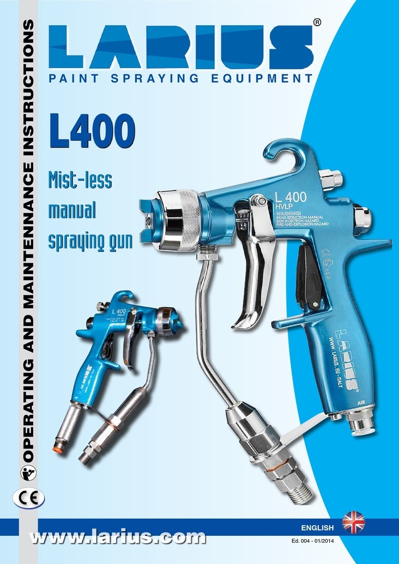
Larius
Larius ZEFIRO Operating manual

Larius
Larius Sirio 27:1 User manual

Larius
Larius PLA K11421 User manual

Larius
Larius DALI Manual

Larius
Larius Excalibur Liner Operating manual

Larius
Larius THOR Operating manual

Larius
Larius STAR 3001S User manual

Larius
Larius L400 Series User manual

Larius
Larius CH 200 AD Operating manual

Larius
Larius TORNADO 2 Series Manual