Ryobi RGBV3100 User manual

• OPERATOR’S MANUAL . . . . . . . . . . . . . . . 2
• MANUEL D’UTILISATION . . . . . . . . . . . . . 16
• BENUTZERHANDBUCH . . . . . . . . . . . . . . 30
• MANUALE D’ISTRUZIONI PER L'USO . . 44
• MANUAL DE UTILIZAÇÃO . . . . . . . . . . . 58
• MANUAL DE INSTRUCCIONES . . . . . . . . 72
GB
F
D
I
P
E
RGBV3100
A

NOTE:Advises you of information or instructions vital to
the operation or maintenance of the equipment.
CAUTION: Failure to obey a safety warning
may result in property damage or personal
injury to yourself or to others. Always follow
the safety precautions to reduce the risk of
fire, electric shock, and personal injury.
The purpose of safety symbols is to attract your
attention to possible dangers. The safety symbols, and
their explanations, deserve your careful attention and
understanding. The safety warnings do not by
themselves eliminate any danger. The instructions or
warnings they give are not substitutes for proper
accident prevention measures.
SYMBOL MEANING
SAFETY ALERT SYMBOL: Indicates
danger, warning, or caution. Attention is
required in order to avoid serious personal
injury. May be used in conjunction with other
symbols or pictographs.
THANK YOU
Thank you for buying this quality product.
Read the whole manual and follow all the instructions to keep
your new outdoor power tool in top operating condition.
NOTE: PROOF OF PURCHASE WILL BE REQUIRED
FOR WARRANTY SERVICE.
Make sure this manual is carefully read and understood
before starting or operating this equipment.
INTRODUCTION
2
TABLE OF CONTENTS
I. Rules for Safe Operation . . . . . . . . . . . . . . . . . . . . . . . 3-6
A. Important Safety Information . . . . . . . . . . . . . . . . . . . 3
B. Safety and International Symbols . . . . . . . . . . . . . . 4-5
C. Know Your Unit . . . . . . . . . . . . . . . . . . . . . . . . . . . . . 6
II. Assembly Instructions . . . . . . . . . . . . . . . . . . . . . . . . . 6-8
A. Attaching and Removing the Blower/Vacuum Tube . .6
B. Attaching and Removing the Vacuum Bag . . . . . . . . 7
C. Installing and Adjusting the Shoulder Harness . . . . . 8
III. Oil and Fuel Information . . . . . . . . . . . . . . . . . . . . . . . . . 8
IV. Starting/Stopping Instructions . . . . . . . . . . . . . . . . . . . . 9
V. Operating Instructions . . . . . . . . . . . . . . . . . . . . . . . 10-11
A. Holding the Blower / Vacuum . . . . . . . . . . . . . . . . . . 10
B. Operating Tips . . . . . . . . . . . . . . . . . . . . . . . . . . . . . 10
C. Operating as a Blower . . . . . . . . . . . . . . . . . . . . . . . 10
D. Operating as a Vacuum . . . . . . . . . . . . . . . . . . . . . . 11
E. Clearing a Blocked Tube/Impeller . . . . . . . . . . . . . . 11
F. Empty the Vacuum Bag . . . . . . . . . . . . . . . . . . . . . . 11
VI. Maintenance and Repair Instructions . . . . . . . . . . . 12-13
A. Air Filter Maintenance . . . . . . . . . . . . . . . . . . . . . . . . 12
B. Replacing the Spark Plug . . . . . . . . . . . . . . . . . . . . . 13
VII. Cleaning and Storage . . . . . . . . . . . . . . . . . . . . . . . . . . 13
VIII. Troubleshooting Chart . . . . . . . . . . . . . . . . . . . . . . . . . 14
IX. Specifications . . . . . . . . . . . . . . . . . . . . . . . . . . . . . . . . 15
IX. CE Declaration of Conformity . . . . . . . . . . . . . Back Cover
CONTENTS OF CARTON
This unit includes the following:
•Model RGBV3100 Mulching Blower Vacuum
•Blower/Vacuum Tube
•Shoulder Harness
•Vacuum bag
•Hardware Pack
•Operator's Manual
RGBV3100
2-Cycle Mulching Blower Vacuum
IMPORTANT MANUAL
DO NOT THROW AWAY

RULES FOR SAFE OPERATION
3
• IMPORTANT SAFETY INFORMATION •
READ ALL INSTRUCTIONS
BEFORE OPERATING
•Read the instructions carefully. Be familiar with the controls
and proper use of the unit.
•Inspect the unit before use. Replace damaged parts. Check
for fuel leaks. Make sure all fasteners are in place and
secure. Failure to do so can result in personal injury to the
operator and bystanders, as well as damage to the unit
•Be aware of the risk of injury to the head, hands and feet.
•Clear the area of children, bystanders, and pets. At a
minimum, keep all children, bystanders and pets outside a
15 meters. (50 ft.) radius; there still may be a risk to
bystanders from thrown objects. Bystanders should be
encouraged to wear eye protection. If you are approached,
stop the engine immediately.
SAFETY WARNINGS FOR PETROL UNITS
WARNING: Petrol (gasoline) is highly flammable, and its
vapors can explode if ignited. Take the following precautions:
•Store fuel only in containers specifically designed and
approved for the storage of such materials.
•Avoid creating a source of ignition for spilled fuel. Do not
start the engine until fuel vapors dissipate.
•Always stop the engine and allow it to cool before filling the
fuel tank. Never remove the cap of the fuel tank, or add fuel,
when the engine is hot. Never operate the unit without the
fuel cap securely in place. Loosen the fuel tank cap slowly to
relieve any pressure in the tank.
•Remove the vacuum bag before refueling.
•Mix and add fuel in a clean, well-ventilated area outdoors
where there are no sparks or flames. Slowly remove the
fuel cap only after stopping engine. Do not smoke while
fueling or mixing fuel. Wipe up any spilled fuel from the unit
immediately.
WHILE OPERATING
•Never start or run the unit inside a closed room or building.
Breathing exhaust fumes can kill. Operate this unit only in a
well ventilated area outdoors.
•Wear safety glasses or goggles and ear/hearing protection
when operating this unit. Wear a face or dustmask if the
operation is dusty. Long sleeve shirts are recommended.
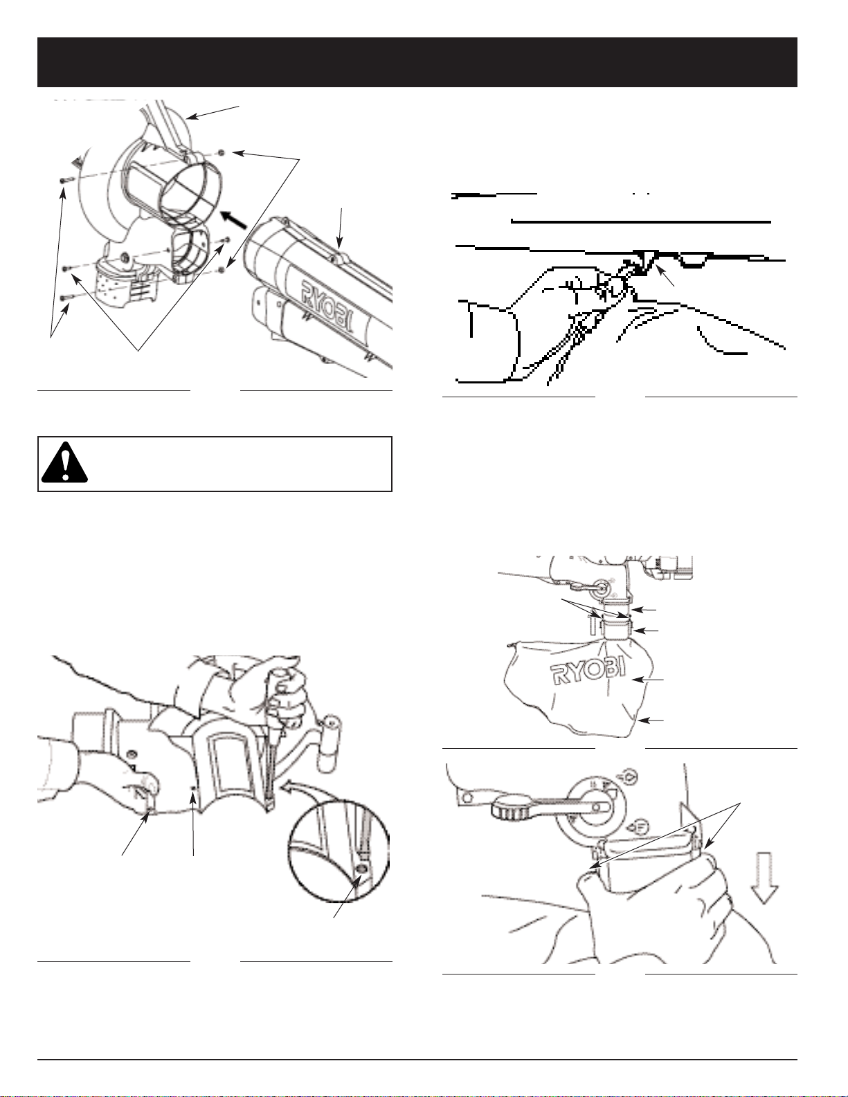
•Never run the unit without the the proper equipment
attached. When using this unit, always install the
blower/vacuum tube, vacuum bag and make sure
the vacuum bag is completely zipped closed.
•Stop and switch the engine to off for maintenance, repair, to
install or remove the blower/vacuum tubes or vacuum bag.
The unit must be stopped and the impeller no longer turning
to avoid contact with the rotating blades.
•Avoid accidental starting. Be in the starting position whenev-
er pulling the starter rope. The operator and unit must be in a
stable position while starting. See Starting/Stopping
Instructions.
•Do not overreach. Always keep proper footing and balance.
•Do not touch the engine or muffler. These parts get
extremely hot from operation. When turned off they remain
hot for a short time.
•Do not operate the unit with loose or damaged parts. Do not
operate before repairing damage.
•Use only genuine Ryobi replacement parts when servicing
this unit. These parts are available from your authorized
service dealer. Do not use parts, accessories or attachments
not authorized by Ryobi for this unit. Doing so could lead to
serious injury to the user, or damage to the unit, and void
your warranty.
•Do not set unit on any surface except a clean, hard area
while engine is running. Debris such as gravel, sand, dust,
grass, etc. could be picked up by the air intake and thrown
out by the discharge opening, damaging unit, property, or
causing serious injury to bystanders or operator.
•Keep hands, face, and feet at a distance from all moving
parts. Do not touch or try to stop the impeller when it is
rotating.
•Never use this unit for spreading chemicals, fertilizers, or
other substances which may contain toxic materials.
WHILE OPERATING UNIT AS A BLOWER
•Never point the Blower in the direction of people or pets, or
in the direction of windows. Always direct the blowing debris
away from people, animals, glass, and solid objects such as
trees, automobiles, walls, etc.
WHILE OPERATING UNIT AS A VACUUM
•Avoid situations that could catch the vacuum bag
on fire. Do not operate near an open flame. Do not
vacuum warm ash from fireplaces, barbecue pits, brush
piles, etc. Do not vacuum discarded cigars or cigarettes
unless the cinders are completely cool.
•The unit is designed to pickup dry material such as leaves,
grass, small twigs and bits of paper. Do not attempt to
vacuum wet debris and/or standing wateras this may result
in damage to the Blower/ Vacuum. To avoid severe damage
to the impeller, do not vacuum metal, broken glass, etc.
OTHER SAFETY WARNINGS
•Allow the engine to cool before storing or transporting. Be
sure to secure the unit while transporting.
•Store the unit in a dry area, locked up or up high, to prevent
unauthorized use or damage. Keep out of
the reach of children.
•Never douse or squirt the unit with water or any other liquid.
Keep handles dry, clean and free from debris. Clean after
each use, see Cleaning and Storage instructions.
SAVE THESE INSTRUCTIONS

RULES FOR SAFE OPERATION
4
SAFETY AND INTERNATIONAL SYMBOLS
This operator's manual describes safety and international symbols and pictographs that may appear on this product.
Read the operator's manual for complete safety, assembly, operating and maintenance and repair information.
SYMBOL MEANING
•SAFETY ALERT SYMBOL
Indicates danger, warning, or caution. May be used in conjunction with other
symbols or pictographs.
•WARNING - READ OPERATOR'S MANUAL
Read the Operator’s Manual(s) and follow all warnings and safety instructions.
Failure to do so can result in serious injury to the operator and/or bystanders.
•WEAR EYE AND HEARING PROTECTION
WARNING: Thrown objects and loud noise can cause severe eye injury and hearing loss.
Wear eye protection and ear protection when operating this unit.
•KEEP BYSTANDERS AWAY
WARNING: Keep all bystanders, especially children and pets, at least 15 meters (50 ft.)
from the operating area.
•PRIMER
Push primer bulb, fully and slowly, 5 to 7 times.
•UNLEADED FUEL
Always use clean, fresh unleaded fuel.
•OIL
Refer to operator's manual for the proper type of oil.
•THROWN OBJECTS CAN CAUSE SEVERE INJURY
WARNING: Keep clear of blower outlet. Never point the blower at yourself or others.
Objects can be thrown from blower. Do not operate unit without proper attachments and
guards in place.
WARNING: The operation of any power tool can cause foreign objects to be
thrown into your eyes. This can lead to severe eye damage. Before commencing
power tool operation, always wear safety glasses or goggles, and a full face
shield when needed.

RULES FOR SAFE OPERATION
5
SYMBOL MEANING
•IGNITION SWITCH
ON / START / RUN
•IGNITION SWITCH
OFF OR STOP
•HOT SURFACE WARNING
Do not touch a hot muffler or cylinder. You may get burned. These parts get extremely hot
from operation. When turned off they remain hot for a short time.
•CHOKE CONTROL
A • FULL choke position.
B • PARTIAL choke position.
C • RUN position.
•BLOWERS AND BLOWER/VACUUMS – ROTATING IMPELLER BLADES CAN
CAUSE SEVERE INJURY
WARNING: Stop the engine and allow the impeller to stop before installing or changing
tubes or bag, or before cleaning or performing any maintenance.
•BLOWER/VACUUM MODE CHANGE-OVER LEVER
A - Vacuum mode
B - Blower mode
•THROTTLE CONTROL
Indicates “HIGH” or “FASTEST” speed.
•THROTTLE CONTROL
Indicates “IDLE”, “LOW” or “SLOWEST” speed.

ASSEMBLY INSTRUCTIONS
RULES FOR SAFE OPERATION
6
ATTACHING AND REMOVING THE BLOWER/
VACUUM TUBE
Attaching
NOTE: The Blower/Vacuum Tube comes unassembled
on this unit. Installation is required to provide
safe and easy use for the operator.
1. Remove the screws and nuts provided from the
hardware pack.
2. Insert the blower/vacuum tube all the way into the
opening on the motor housing until the holes in the
tabs on the blower/vacuum tube align with the screw
holes in the housing (Fig. 1).
APPLICATION
As a blower;
•Cleaning of yards, garages, driveways, porches,
patios, around walls, fences, etc.
As a vacuum;
•Picking up leaves, light debris, etc.
Harness
Blower/Vacuum Tube
Vacuum Bag
Blower/Vacuum Mode
Change-Over Lever
Blower/Vacuum Inlet
Blower Outlet
Vacuum Bag Hook
Vacuum Bag Zipper
Fuel Cap
Throttle Lever
Primer
Choke Lever
Air filter/muffler cover
Spark Plug
Starter Rope
Grip
Ignition Switch
KNOW YOUR UNIT
3. Insert the 2 (two) 8-32 x 3/4” slotted T20 Torx screws
into the right side of the motor housing and the 2
(two) nuts into the left side of the motor housing
(Fig. 2).
4. Tighten the screws firmly. Do not over-tighten.
5. Install the 2 (two) remaining self-tapping 8-16 x 3/4”
slotted T20 Torx screws into the holes on either side
of the housing (Fig. 2). Tighten until snug, do not
over-tighten.

ASSEMBLY INSTRUCTIONS
7
Vacuum Bag Hook
Fig. 3
ATTACHING AND REMOVING THE VACUUM BAG
Attaching
1. Attach the vacuum bag to the vacuum bag hook on
the blower/vacuum tube (Fig. 3)
2. Slide the vacuum bag tube over the debris exhaust
tube on the housing. Push the tube until the latching
tabs on both sides click into place, securing the bag
on the unit (Fig. 4).
Removing
1. Press the latching tabs on both sides of the vacuum bag
tube and pull the vacuum bag from the unit (Fig. 5).
2. Detach the vacuum bag from the vacuum bag hook.
Screw
and Nut
Screw and Nut
Self Tapping
Screw
Fig. 1
Removing
WARNING: To prevent serious personal injury,
stop the engine and allow the impeller to stop
before attaching or removing tubes.
1. Remove the 2 (two) self-tapping screws from either
side of the housing.
2. Remove the 2 (two) screws and nuts holding the
blower/vacuum tube on the housing (Fig. 1).
NOTE: Keep the hardware in a safe place for future use.
3. Remove the blower/vacuum tube from the motor
housing.
4. Replace Blower/Vacuum Tube before use.
Fig. 2
Screw
Nut
Blower/Vacuum
Tube
Motor Housing
Self-Tapping Screw
Fig. 5
Latching Tabs
Vacuum Bag
Debris Exhaust Tube
Vacuum Bag Tube
Zipper
Fig. 4
Latching Tabs

WARNING: petrol (gasoline) is extremely
flammable and its vapors can explode if they
are ignited. Always stop the engine and allow
it to cool before filling the fuel tank. Do not
smoke while filling the tank. Keep sparks and
open flames away from the area.
OIL AND FUEL MIXING INSTRUCTIONS
Thoroughly mix 5 liters of unleaded petrol (gasoline) with
100 ml. of 2 cycle engine synthetic oil in a separate fuel
can, (50:1 = 2%). Do not mix them directly in the engine
fuel tank.
OIL AND FUEL INFORMATION
ASSEMBLY INSTRUCTIONS
8
Clip
INSTALLING AND ADJUSTING THE SHOULDER
HARNESS
NOTE: Have the shoulder harness on and adjusted, but
not clipped to the support fitting prior to starting
unit.
1. Push the strap through the center of the buckle.
2. Pull the strap over the cross bar and down through
the slot in the buckle (Fig. 6).
3. Fully extend the harness.
Fig. 6
Fig. 7
Support Fitting
4. Attach the metal clip of the shoulder harness to the
support fitting on top of the handle (Fig. 7).
Clip Fig. 9
Fig. 8
5. Place the harness over your head and onto your
shoulder (Fig. 8).
6. While standing in the operating position (Fig. 8)
adjust length to fit the operator’s size.
•Lengthen the harness by pulling down on the strap
and lifting the buckle end up (Fig. 9).
•Shorten the harness by pulling the strap back
through the buckle while holding the buckle (Fig. 9).
Old and/or improperly mixed fuel are usually the main
reasons for the unit not running properly. Be sure to use
fresh, clean fuel and follow the instructions carefully for
the proper fuel/oil mixture.
RECOMMENDED OIL TYPE
Use a high quality synthetic oil formulated for use in 2-
cycle,
air-cooled engines.
RECOMMENDED FUEL TYPE
Always use clean, fresh, unleaded petrol (gasoline) that
is less than 60 days old.

STARTING/STOPPING INSTRUCTIONS
9
STARTING INSTRUCTIONS
1. Mix petrol (gasoline) with oil. Fill fuel tank with fuel/oil
mixture. See Oil and Fuel Mixing Instructions on pg. 8.
WARNING: To avoid serious personal injury,
always remove the vacuum bag prior to
refueling the unit. The bag may become a
fire hazard when saturated with fuel.
NOTE: Have the shoulder harness on and adjusted, but
not clipped to the support fitting prior to starting
unit.
NOTE: Fast position is to the right. The throttle lever
will remain in position until moved.
NOTE: Setting the lever to the blower mode prevents
the vacuum bag from filling up while starting the
engine.
NOTE: The ignition switch is a momentary switch and is
always in th ON (I) position (Fig. 10).
2. Set the blower/vacuum mode change-over lever to
the up position (Blower Mode). See Operating as a
Blower, pg. 10.
3. Fully press and release primer bulb slowly 5 to 7
times. Fuel should be felt and visible in the bulb
(Fig. 11). If fuel hasn’t entered the bulb, press three
more times, or until it does.
4. Place the choke lever in the FULL choke (A)
position (Fig. 11).
5. With the unit on the ground, move the throttle lever
to the fast position ( ) (Fig. 10).
6. Pull starter rope briskly (Fig. 12). Continue pulling
until the engine sounds as though it wants to run
(normally 2 to 5 pulls).
7. Place the choke lever in the PARTIAL (B) position
(Fig. 11).
NOTE: The unit will not run in the FULL choke (A)
position.
8. Pull starter rope briskly 1 to 3 times to start the
engine (Fig. 12).
9. If the engine does not start, repeat steps 3
through 6.
Ignition Switch
Fig. 10
Throttle Lever Idle Fast
AB C
Choke Lever
Full Choke Position (A)
Primer Bulb
Fig. 11
Run Position (C)
Partial Position (B)
Starter Rope
Fig. 12
10. Allow the engine to warm up for 5 to 10 seconds.
Place the choke lever in the RUN (C) position
(Fig. 11).
11. Stand in the operating position and clip the shoulder
harness to the support fitting
NOTE: If the engine floods while trying to start, place the
choke lever in the RUN (C) position . Move
the throttle lever to the fast position ( )
(Fig 10). Pull the starter rope briskly. The engine
should start with three (3) to eight (8) pulls.
NOTE: Choking is unnecessary when starting a warm
engine. Put the throttle lever in the fast position
() (Fig 10) and start unit with the choke lever
in the PARTIAL (B) position (Fig. 11).
STOPPING INSTRUCTIONS
1. Move the throttle lever to the idle position ( )
(Fig. 10). Allow the engine to cool down by
idling.
2. Press and hold the Ignition Switch down in the
STOP [O] position until the engine comes to a
complete stop (Fig. 10).

OPERATING INSTRUCTIONS
10
Fig. 15
Fig. 16
Fig. 19
Change-over lever
Vacuum
Mode
Blower
Mode
OPERATING AS A BLOWER
1. Start engine. See Starting/Stopping Instructions
Pg. 9.
2. Set the blower/vacuum mode change-over lever to
the up position (Blower Mode) (Fig. 14).
NOTE: Never use the unit with the lever in the halfway
position.
3. Place the shoulder harness over your head and onto
your shoulder and adjust properly, see Installing
and Adjusting the Shoulder Harness Pg. 8.
Hold the blower as shown in Figs. 15, 16, and 17. Sweep
from side to side with the nozzle several inches above
the ground or floor. Slowly advance, keeping the
accumulated pile of debris in front of you.
Fig. 14
Most dry blowing operations are better suited to low
speed than high, while high speed is better for moving
heavier items like large debris or gravel.
Use the blower for trees, shrubs, flower beds and
hard to clean areas (Fig. 15).
Use the blower around buildings and for other normal
cleaning (Fig. 16).
HOLDING THE BLOWER/VACUUM
Before operating the unit, stand in the operating position
(Fig. 13). Check for the following:
•Operator is wearing proper clothing, such as boots,
safety glasses or goggles, ear/hearing protection,
gloves, long pants and long sleeve shirt.
Fig. 13
OPERATING TIPS
•Be sure the vacuum bag is zipped closed before
operating the unit.
•Assure the unit is not directed at loose debris or
persons before starting unit.
•The unit is in good working condition. The tubes and
guards are in place and secure.
•Always hold the unit with both hands when
operating. Keep a firm grip on both the front and rear
handle or grips.
•To reduce the risk of hearing loss associated with
sound level(s), the use of hearing protection is
required.
•Watch out for children, pets, open windows, or
freshly washed cars, and blow debris away.
•After using blowers and other equipment, CLEAN
UP! Dispose of debris in trash receptacles.

OPERATING INSTRUCTIONS
11
Use the blower for walls, overhangs and screens
(Fig. 17).
Fig. 17
OPERATING AS A VACUUM
1. Start engine. See Starting/Stopping Instructions
Pg. 9.
2. Set the blower/vacuum mode change-over lever to
the down position (Vacuum Mode) (Fig. 19).
NOTE: Never use the unit with the lever in the halfway
position.
3. Place the shoulder harness over your head and onto
your shoulder and adjust properly, see Installing
and Adjusting the Shoulder Harness, Pg. 8.
Hold the vacuum, tilting the blower/vacuum tube slightly,
and use a sweeping action to collect light debris
(Fig. 19). Small leaves and twigs will flow into the
vacuum bag and be mulched as they pass through the
fan housing, allowing the vacuum bag to hold more
debris.
Change-over lever
Fig. 19
Fig. 18
Vacuum
Mode
Blower
Mode
CLEARING A BLOCKED TUBE / IMPELLER
1. Put the Ignition Switch in the OFF position [O]
(Fig. 10, Pg. 9) and wait for the impeller to stop
rotating.
2. Disconnect the spark plug wire to prevent the unit
from starting.
3. Remove the blower/vacuum tube (pg. 6) and the
vacuum bag (pg. 7).
4. Carefully remove material blocking the tube or
impeller. Inspect the blades to assure no damage
has occurred. Rotate the impeller blades by hand to
assure the blockage is completely cleared.
5. Reinstall the vacuum bag and blower/vacuum tube.
6. Reconnect the spark plug wire.
EMPTY THE VACUUM BAG
1. While pressing the latching tabs on both sides of the
vacuum bag tube, pull the vacuum bag off the unit
(Fig. 20).
2. Detach the vacuum bag from the vacuum bag hook.
3. Unzip the bag and empty the contents into a
garbage bag or container.
4. Turn the bag inside out after initial emptying and
vigorously shake out dust and debris.
5. Zip the bag closed and reinstall vacuum bag.
Fig. 20
Latching tabs

MAINTENANCE AND REPAIR INSTRUCTIONS
12
Fig. 25
Fig. 23
Fig. 24
Choke Lever
Screws Screws
AIR FILTER MAINTENANCE
Removing the Air Filter/Muffler Cover
1. Place the choke lever in the PARTIAL choke
position (B).
NOTE: The choke lever must be in the PARTIAL choke
position (B) (Fig. 21) to remove the air
filter/muffler cover.
2. Remove the four (4) screws securing the air
filter/muffler cover (Fig. 21). Use a flat blade or T-20
Torx bit screwdriver.
3. Pull the cover from the engine. Do not force.
Cleaning the Air Filter
Clean and re-oil the air filter every 10 hours of operation.
It is an important item to maintain. Not maintaining the
air filter will VOID the warranty.
1. Remove the air filter/muffler cover. See Removing
the Air filter/Muffler Cover.
2. Remove the air filter from behind the air filter/muffler
cover (Fig. 22).
3. Wash the filter in detergent and water (Fig. 23). Rinse
the filter thoroughly. Squeeze out excess water.
Allow it to dry completely.
4. Apply enough clean oil to lightly coat the filter
(Fig. 24).
5. Squeeze the filter to spread and remove excess oil
(Fig. 25).
6. Replace the air filter in the air filter/muffler cover
(Fig. 22).
NOTE: Operating the unit without the air filter and air
filter/muffler cover assembly, will VOID the
warranty.
Reinstalling the Air Filter/Muffler Cover
1. Place the air filter/muffler cover over the back of the
carburetor and muffler.
NOTE: The choke lever must be in the PARTIAL choke
position (B) (Fig. 21) to install the air filter/muffler
cover.
Fig. 21
Air Filter
Fig. 22
2. Insert the four (4) screws into the holes in the air
filter/muffler cover (Fig. 21) and tighten. Use a flat
blade or T-20 Torx bit screwdriver. Do not over
tighten. Do not force.

MAINTENANCE AND REPAIR INSTRUCTIONS
13
0.020 in.
(0.5 mm.)
Fig. 26
REPLACING THE SPARK PLUG
Use a Champion RDJ7Y spark plug (or equivalent). The
correct air gap is 0.5 mm (0.020 in.). Remove the plug
after every 50 hours of operation and check its
condition.
1. Stop the engine and allow it to cool. Grasp the plug
wire firmly and pull the cap from the spark plug.
2. Clean dirt from around the spark plug. Remove the
spark plug from the cylinder head by turning a 5/8 in.
socket counterclockwise.
3. Replace cracked, fouled or dirty spark plug. Set the
air gap at 0.5 mm (0.020 in.) using a feeler gauge
(Fig. 26).
CLEANING THE UNIT
•Use a small brush to clean off the outside of the unit
and to keep the air vents free of obstructions.
CLEANING THE VACUUM BAG
1. Empty the bag after each use to avoid deterioration
and obstructing air flow, which will reduce the
performance of the vacuum.
2. Wearing eye protection and a dust mask, clean the
bag as needed. Turn the bag inside out after initial
emptying and vigorously shake out dust and debris.
3. Wash the bag once a year or more often if needed:
a. Remove the vacuum bag.
b. Turn bag inside out.
c. Hang up.
d. Hose down thoroughly.
e. Hang to dry.
f. Turn bag right-side out and reinstall.
STORAGE
•Allow the engine to cool before storing.
•Store the unit locked up to prevent unauthorized use
or damage.
•Store the unit in a dry, well ventilated area.
•Store the unit out of the reach of children.
CLEANING AND STORAGE
4. Install a correctly gapped spark plug in the cylinder
head. Tighten by turning the 5/8 in. socket clockwise
until snug.
If using a torque wrench, torque to;
12.3-13.5 N•m (110-120 in.•lb.).
Do not over tighten.
LONG TERM STORAGE
If the unit will be stored for an extended time,
1. Drain all fuel from the fuel tank into a container. Do
not use fuel that has been stored for more than 60
days. Dispose of the old fuel in accordance to local
regulations.
2. Start the engine and allow it to run until it stalls.
This ensures that all fuel has been drained from the
carburettor.
3. Allow the engine to cool. Remove the spark plug and
put 1 oz. (30 ml.) of high quality motor oil into the
cylinder. Pull the starter rope slowly to distribute the
oil. Reinstall the spark plug.
NOTE: Remove the spark plug and drain all of the oil
from the cylinder before attempting to start the
blower/vacuum after storage.
4. Thoroughly clean the unit and inspect for any loose
or damaged parts. Repair or replace damaged parts
and tighten loose screws, nuts or bolts. The unit is
ready for storage.
TRANSPORTING
•Allow the engine to cool before transporting.
•Secure the unit while transporting.
•Drain the fuel tank before transporting.
•Tighten fuel cap before transporting.

TROUBLESHOOTING
14
CAUSE ACTION
Bag Full Empty Bag. See Empty the Vacuum Bag, Pg. 11
Blocked Tube Clear Blockage. See Clearing a Blocked
tube/Impeller, Pg 11.
Blocked Impeller Clear Blockage. See Clearing a Blocked
tube/Impeller, Pg 11.
Damaged Impeller Take unit to an authorized service dealer
CAUSE ACTION
Old or improperly mixed fuel Drain fuel tank / Add fresh fuel mixture
Improper carburettor adjustment Take to an authorized service dealer for
carburettor adjustment
CAUSE ACTION
Empty fuel tank Fill fuel tank
Primer bulb wasn't pressed enough Press primer bulb fully and slowly 5-7 times
Engine flooded Use starting procedure with choke lever in the
RUN position, Pg. 9
Old or improperly mixed fuel Drain fuel tank / Add fresh fuel mixture
Fouled spark plug Replace or clean the spark plug
ENGINE WILL NOT START
ENGINE WILL NOT IDLE
ENGINE WILL NOT ACCELERATE
ENGINE LACKS POWER OR STALLS WHEN UNDER LOAD
CAUSE ACTION
Air Filter is Plugged Replace or clean the air filter
Old or improperly mixed fuel Drain fuel tank / Add fresh fuel mixture
Improper carburettor adjustment Take to an authorized service dealer for
carburettor adjustment
CAUSE ACTION
Old or improperly mixed fuel Drain fuel tank / Add fresh fuel mixture
Improper carburettor adjustment Take to an authorized service dealer for
carburettor adjustment
UNIT WILL NOT BLOW OR VACUUM

SPECIFICATIONS
15
Engine Type . . . . . . . . . . . . . . . . . . . . . . . . . . . . . . . . . . . . . . . . . . . . . . . . . . . . . . . . . . . . . . . . . Air-Cooled, 2-Cycle
Displacement . . . . . . . . . . . . . . . . . . . . . . . . . . . . . . . . . . . . . . . . . . . . . . . . . . . . . . . . . . . . . . . . . 31 cm3(1.9 cu. in.)
Maximum Engine Performance in accordance with ISO 8893 . . . . . . . . . . . . . . . . . . . . . . . . . . . . . . . . .75 kw (1 hp)
Operating RPM . . . . . . . . . . . . . . . . . . . . . . . . . . . . . . . . . . . . . . . . . . . . . . . . . . . . . . . . . . . . . . . . . 6,600-8,000 rpm
Idle Speed RPM . . . . . . . . . . . . . . . . . . . . . . . . . . . . . . . . . . . . . . . . . . . . . . . . . . . . . . . . . . . . . . . . . 2,800-3,900 rpm
Ignition Type . . . . . . . . . . . . . . . . . . . . . . . . . . . . . . . . . . . . . . . . . . . . . . . . . . . . . . . . . . . . . . . . . . . . . . . . . Electronic
Ignition Switch . . . . . . . . . . . . . . . . . . . . . . . . . . . . . . . . . . . . . . . . . . . . . . . . . . . . . . . . . . Momentary Rocker Switch
Spark Plug Gap . . . . . . . . . . . . . . . . . . . . . . . . . . . . . . . . . . . . . . . . . . . . . . . . . . . . . . . . . . . . . . . . 0.5 mm (0.020 in.)
Lubrication . . . . . . . . . . . . . . . . . . . . . . . . . . . . . . . . . . . . . . . . . . . . . . . . . . . . . . . . . . . . . . . . . . . . . . Fuel/Oil Mixture
Fuel/Oil Ratio . . . . . . . . . . . . . . . . . . . . . . . . . . . . . . . . . . . . . . . . . . . . . . . . . . . . . . . . . . . . . . . . . . . . . . . . 50:1 = 2%
Carburettor . . . . . . . . . . . . . . . . . . . . . . . . . . . . . . . . . . . . . . . . . . . . . . . . . . . . . . . . . . . . . . . Diaphragm, All-Position
Starter . . . . . . . . . . . . . . . . . . . . . . . . . . . . . . . . . . . . . . . . . . . . . . . . . . . . . . . . . . . . . . . . . . . . . . . . . . . . Auto Rewind
Muffler . . . . . . . . . . . . . . . . . . . . . . . . . . . . . . . . . . . . . . . . . . . . . . . . . . . . . . . . . . . . . . . . . . . . . . . Baffled with Guard
Throttle . . . . . . . . . . . . . . . . . . . . . . . . . . . . . . . . . . . . . . . . . . . . . . . . . . . . . . . . . . . . . . . . . . . . . . . . . . . . . . . . Manual
Fuel Tank Capacity . . . . . . . . . . . . . . . . . . . . . . . . . . . . . . . . . . . . . . . . . . . . . . . . . . . . . . . . . . . . . . . . 415 ml (14 oz.)
Fuel Tank . . . . . . . . . . . . . . . . . . . . . . . . . . . . . . . . . . . . . . . . . . . . . . . . . . . . . . . . . . . . . . . . . . . . . . . HD Polyethylene
Throttle Control . . . . . . . . . . . . . . . . . . . . . . . . . . . . . . . . . . . . . . . . . . . . . . . . . . . . . . . . . . . . . . . . . . Finger-Tip Lever
Blower Velocity . . . . . . . . . . . . . . . . . . . . . . . . . . . . . . . . . . . . . . . . . . . . . . . . . . . . . . . . . . . up to 257 kmh (160 mph)
Blower Air Output . . . . . . . . . . . . . . . . . . . . . . . . . . . . . . . . . . . . . . . . . . . . . . . . . . . . . . . . . up to 12.1 cmm (424 cfm)
Mulching Ratio . . . . . . . . . . . . . . . . . . . . . . . . . . . . . . . . . . . . . . . . . . . . . . . . . . . . . . . . . . . . . . . . . . . . . . . up to 10:1
Vacuum Bag Capacity . . . . . . . . . . . . . . . . . . . . . . . . . . . . . . . . . . . . . . . . . . . . . . . . . . . . . 35.24 Liters (1.0 bushels)
Shoulder Harness . . . . . . . . . . . . . . . . . . . . . . . . . . . . . . . . . . . . . . . . . . . . . . . . . . . . . . . . . . . . . . Single Quick-Snap
Mass (no fuel, with blower/vacuum tube and vacuum bag, vacuum bag empty) . . . . . . . . . . . . . . . 6.1 kg (13.5 lb.)
The following levels were done with the unit in the blower mode:
Front Vibration Level (Idle)
*
. . . . . . . . . . . . . . . . . . . . . . . . . . . . . . . . . . . . . . . . . . . . . . . . . . . . . . . . . . . . . . 5.41 m/s2
Rear Vibration Level (Idle)
*
. . . . . . . . . . . . . . . . . . . . . . . . . . . . . . . . . . . . . . . . . . . . . . . . . . . . . . . . . . . . . . 6.33 m/s2
Front Vibration Level (Operating RPM)
*
. . . . . . . . . . . . . . . . . . . . . . . . . . . . . . . . . . . . . . . . . . . . . . . . . . . . 5.88 m/s2
Rear Vibration Level (Operating RPM)
*
. . . . . . . . . . . . . . . . . . . . . . . . . . . . . . . . . . . . . . . . . . . . . . . . . . . . . 9.09 m/s2
Sound Pressure Level (Idle) †. . . . . . . . . . . . . . . . . . . . . . . . . . . . . . . . . . . . . . . . . . . . . . . . . . . . . . . . 76.0 LpeqdB(A)
Sound Power Level (Idle) ‡. . . . . . . . . . . . . . . . . . . . . . . . . . . . . . . . . . . . . . . . . . . . . . . . . . . . . . . . . . 96.0 LweqdB(A)
Sound Pressure Level (Operating RPM) †. . . . . . . . . . . . . . . . . . . . . . . . . . . . . . . . . . . . . . . . . . . . . . 86.0 LpeqdB(A)
Sound Power Level (Operating RPM) ‡. . . . . . . . . . . . . . . . . . . . . . . . . . . . . . . . . . . . . . . . . . . . . . . 106.0 LweqdB(A)
*
Method for obtaining level per ISO 7916
†Method for obtaining level per EN 27917
‡Method for obtaining level per ISO 108847
ENGINE
BLOWER / VACUUM

16
REMARQUE :Fournit des informations ou instructions
essentielles pour le fonctionnement ou
l’entretien de l'outil.
PRECAUTION : Le non-respect d’un
avertissement de sécurité peut entraîner des
dommages matériels ou des blessures
corporelles pour l’utilisateur ou des tiers.
Respectez toujours les règles de sécurité
afin de réduire les risques d’incendie, de
décharge électrique et de blessure corporelle.
Les symboles de sécurité sont destinés à attirer votre
attention sur d’éventuels dangers. Soyez très attentif à ces
symboles et aux explications qui les accompagnent, et
assurez-vous de les avoir bien compris. Les avertissements
sur la sécurité ne suffisent pas à éliminer le danger. Les
instructions ou mises en garde qu’ils comportent ne se
substituent pas aux mesures de prévention des accidents
qu’il convient d’appliquer.
SIGNIFICATION DES SYMBOLES
SYMBOLE D’ALERTE DE SECURITE : Ce
symbole indique un danger, donne un
avertissement ou invite à prendre des précau-
tions. Il est indispensable d'être attentif pour
éviter des blessures graves. Il peut être combiné
à d’autres symboles ou pictogrammes.
MERCI
Nous vous remercions d’avoir acheté ce produit de qualité.
Lisez l’intégralité du manuel et respectez toutes les consignes
afin de conserver votre nouvel outil à moteur d’extérieur en
excellent état de fonctionnement.
REMARQUE :UNE PREUVE D’ACHAT VOUS SERA
DEMANDEE POUR TOUT SERVICE LIE A LA
GARANTIE.
Assurez-vous d’avoir lu attentivement et compris les
instructions fournies dans ce manuel avant de démarrer
ou d’utiliser cet outil.
INTRODUCTION TABLE DES MATIERES
I. CONSIGNES DE SECURITE . . . . . . . . . . . . . . . . 17-20
A. Informations importantes sur la sécurité . . . . . . . 17
B. Symboles de sécurité et symboles
internationaux . . . . . . . . . . . . . . . . . . . . . . . . . 18-19
C. Description . . . . . . . . . . . . . . . . . . . . . . . . . . . . . . 20
II. Instructions de montage . . . . . . . . . . . . . . . . . . . 20-22
A. Montage et démontage du tube du
souffleur/aspirateur . . . . . . . . . . . . . . . . . . . . . . . .20
B. Montage et démontage du sac de l’aspirateur . . 21
C. Installation et réglage du harnais . . . . . . . . . . . . . 22
III. Informations sur l’huile et le carburant . . . . . . . . . . . 22
IV. Instructions pour le démarrage et l’arrêt . . . . . . . . . 23
V. Instructions d’utilisation . . . . . . . . . . . . . . . . . . . 24-25
A. Prise en main du souffleur/aspirateur . . . . . . . . . 24
B. Conseils d’utilisation . . . . . . . . . . . . . . . . . . . . . . 24
C. Utilisation comme souffleur . . . . . . . . . . . . . . . . . 24
D. Utilisation comme aspirateur . . . . . . . . . . . . . . . . 25
E. Désobstruction d’un tube ou d’un rotor bouché . 25
F. Vidage du sac de l’aspirateur . . . . . . . . . . . . . . . 25
VI. Entretien et réparations . . . . . . . . . . . . . . . . . . . . .26-27
A. Entretien du filtre à air . . . . . . . . . . . . . . . . . . . . . .26
B. Remplacement de la bougie . . . . . . . . . . . . . . . . .27
VII. Nettoyage et stockage . . . . . . . . . . . . . . . . . . . . . . . 27
VIII.Dépannage . . . . . . . . . . . . . . . . . . . . . . . . . . . . . . . . 28
IX. Caractéristiques techniques . . . . . . . . . . . . . . . . . . . 29
X. Déclaration de conformité CE . . . . . Couvercle arrière
CONTENU DE L’EMBALLAGE
Vous devez disposer des éléments suivants :
•Broyeur aspirateur souffleur, modèle RGBV3100
•Tube du souffleur/aspirateur
•Harnais
•Sac de l’aspirateur
•Paquet d’accessoires
•Manuel d’utilisation
RGBV3100
Broyeur aspirateur souffleur thermique 2 temps
MANUEL IMPORTANT
A CONSERVER

17
CONSIGNES DE SECURITE
LISEZ TOUTES LES INSTRUCTIONS AVANT D’UTILISER
VOTRE OUTIL
•Lisez attentivement les instructions. Familiarisez-vous avec
les commandes et le mode d’utilisation de votre appareil.
•Contrôlez l’appareil avant de l’utiliser. Remplacez les pièces
endommagées. Vérifiez qu’il n’y a pas de fuite de carburant.
Assurez-vous que la boulonnerie est bien en place et que
tous les éléments sont correctement fixés. Le non-respect
de ces règles peut entraîner des blessures corporelles pour
l’utilisateur ou les personnes se trouvant à proximité, ainsi
qu’une détérioration de l’appareil.
•Attention aux risques de blessure à la tête, aux mains et aux
pieds.
•Eloignez les enfants, les passants et les animaux de la zone
concernée. Ils doivent se trouver à une distance minimum de
quinze mètres. Même à cette distance, les risques de
projections ne sont pas exclus. Le port de lunettes de
protection est recommandé pour les personnes se trouvant
à proximité. Si quelqu’un s’approche de vous, coupez
immédiatement le moteur.
CONSIGNES DE SECURITE POUR LES OUTILS A ESSENCE
ATTENTION : L’essence est hautement inflammable et les
vapeurs d’essence peuvent exploser en cas de contact
avec une flamme. Prenez les précautions suivantes :
•Stockez toujours le carburant dans des conteneurs
spécialement conçus et agréés pour le stockage
de ce type de produit.
•Evitez de créer une source d’ignition près d’un déversement
de carburant. Ne démarrez pas le moteur tant que les
vapeurs d’essence ne se sont pas dissipées.
•Arrêtez toujours le moteur et laissez-le refroidir avant de
remplir le réservoir. Vous ne devez jamais enlever le
bouchon du réservoir ou ajouter du carburant tant que le
moteur est chaud.Desserrez lentement le bouchon du
réservoir afin de réduire la pression dans le réservoir.
•Enlevez le sac de l’aspirateur avant de procéder au
ravitaillement en carburant.
•Effectuez le mélange et le ravitaillement dehors, dans un
endroit propre et bien ventilé, où il n’y a ni étincelle, ni
flamme. Enlevez lentement le bouchon du réservoir, unique-
ment après avoir arrêté le moteur. Ne fumez pas pendant
que vous ajoutez ou que vous mélangez le carburant.
PENDANT L’UTILISATION
•Ne démarrez et n’utilisez jamais l’appareil dans une pièce ou
un bâtiment fermé. L’inhalation des fumées d’échappement
peut être mortelle. N’utilisez cet équipement qu’en extérieur,
dans une zone bien ventilée.
•Portez des lunettes de protection et des protections antibruit
lorsque vous utilisez cet appareil. En présence de poussière,
portez un masque anti-poussière.
•N’utilisez jamais cet appareil sans l’équipement approprié.
Installez toujours le tube du souffleur/aspirateur et le sac de
l’aspirateur et assurez-vous que ce dernier est complète-
ment fermé.
•Éteignez le moteur et mettez-le en position Arrêt pour toute
opération d’entretien ou de maintenance, pour installer ou
enlever le tube du souffleur/aspirateur ou le sac de l’aspira-
teur. L’appareil doit être arrêté et le rotor ne doit plus tourner
pour éviter tout contact avec les lames en rotation.
•Evitez tout démarrage fortuit. Soyez en position de démar-
rage lorsque vous tirez sur la corde du lanceur. L’utilisateur
et l’appareil doivent être en position stable lors du démar-
rage. Reportez-vous aux Instructions pour le démarrage et
l’arrêt.
•N’utilisez pas l’appareil de manière inconsidérée. Maintenez
toujours une bonne position et un bon équilibre.
•Ne touchez pas le moteur et le pot d’échappement. Ces élé-
ments chauffent énormément lorsque l’appareil est en fonc-
tionnement. Une fois qu’il est arrêté, ils restent chauds pen-
dant un court moment.
•N’utilisez pas cet appareil si certaines pièces sont mal ser-
rées ou endommagées. Effectuez la remise en état avant
d’utiliser l’appareil.
•Utilisez uniquement des pièces de rechange de marque
Ryobi pour l’entretien de cet appareil. Ces pièces sont
disponibles auprès de votre distributeur agréé. N’utilisez pas
de pièces, d’accessoires ou d’éléments non homologués par
Ryobi pour cet appareil. Cela pourrait entraîner de sérieuses
blessures pour l’utilisateur, endommager l’appareil et
annuler la garantie.
•Lorsque le moteur est en marche, ne posez l’appareil sur
aucune surface qui ne soit pas propre et dure. Des débris
comme le gravier, le sable, la poussière, l’herbe, etc., pour-
raient être aspirés et rejetés par l’ouverture d’évacuation, ce
qui risquerait d’endommager l’appareil, de provoquer des
dégâts ou de blesser sérieusement l’utilisateur ou les per-
sonnes se trouvant à proximité.
•Tenez vos mains, votre visage et vos pieds à distance de
toute pièce en mouvement. Ne touchez pas le rotor et n’es-
sayez pas de l’arrêter pendant qu’il tourne.
•N’utilisez jamais cet appareil pour répandre des produits
chimiques, des engrais ou autres substances susceptibles
de contenir des composants toxiques.
LORSQUE VOUS UTILISEZ L’APPAREIL COMME
SOUFFLEUR
•Ne dirigez jamais le souffleur vers des personnes ou des ani-
maux, ou vers des fenêtres. Dirigez toujours les débris souf-
flés dans une direction où il n’y a pas de personnes, d’ani-
maux de fenêtres, ni d’objets solides comme des arbres, des
voitures, des murs, etc.
LORSQUE VOUS UTILISEZ L’APPAREIL COMME
ASPIRATEUR
•Cet appareil est destiné à ramasser des matériaux secs
comme des feuilles, de l’herbe, des brindilles et des bouts
de papier. N’essayez pas d’aspirer des débris humides ou
de l’eau car vous risqueriez d’endommager votre souffleur
aspirateur. N’aspirez pas de métal, de débris de verre, etc.,
car vous risqueriez d’abîmer sérieusement le rotor.
AUTRES AVERTISSEMENTS DE SECURITE
•Laissez le moteur refroidir avant de ranger ou de transporter
l’appareil. Veillez à protéger l’appareil pour le transport.
•Entreposez l’appareil dans un endroit sec, fermé à clé ou en
hauteur afin d’empêcher une utilisation non autorisée ou un
endommagement. Tenez-le hors de portée des enfants.
•N’immergez jamais l’appareil et ne l’aspergez jamais d’eau
ou de tout autre liquide. Veillez à ce que les poignées restent
sèches, propres et sans débris. Nettoyez l’appareil après
chaque utilisation ; reportez-vous aux instructions de la sec-
tion " Nettoyage et stockage ".
CONSERVEZ CES INSTRUCTIONS
• INFORMATIONS IMPORTANTES SUR LA SECURITE •

18
CONSIGNES DE SECURITE
SYMBOLES DE SECURITE ET SYMBOLES INTERNATIONAUX
Le présent manuel d’utilisation décrit les symboles et pictogrammes de sécurité et internationaux susceptibles d’apparaître sur cet outil.
Lisez le manuel d’utilisation pour obtenir des informations complètes sur la sécurité, le montage, le fonctionnement, l’entretien et la
maintenance de votre matériel.
SYMBOLE SIGNIFICATION
•SYMBOLE D’ALERTE DE SECURITE
Ce symbole indique un danger, donne un avertissement ou invite à prendre des précautions.
Il peut être combiné à d’autres symboles ou pictogrammes.
•ATTENTION – LIRE LE MANUEL D’UTILISATION
Lisez le manuel d’utilisation et suivez tous les avertissements et consignes de sécurité.
Le non-respect de ces instructions peut entraîner de graves blessures pour l’utilisateur et/ou
les personnes se trouvant à proximité.
•PORTER DES PROTECTIONS OCULAIRES ET AUDITIVES
ATTENTION : Les projections d’objets et le niveau sonore peuvent provoquer des lésions aux
yeux et une perte auditive. Portez des lunettes protectrices et une protection antibruit lors de
l’utilisation de l’appareil.
•TENIR TOUTE PERSONNE A DISTANCE
ATTENTION : Toutes les personnes se trouvant à proximité, notamment les enfants, ainsi que
les animaux, doivent se trouver à une distance d’au moins 15 mètres de la zone où est utilisé
l’appareil.
•AMORÇAGE
Appuyez 5 à 7 fois, lentement et à fond, sur la pompe d’amorçage.
•ESSENCE SANS PLOMB
Utilisez toujours une essence sans plomb, propre et neuve.
•HUILE
Reportez-vous au manuel d’utilisation pour connaître le type d’huile à utiliser.
•LES PROJECTIONS D’OBJETS PEUVENT PROVOQUER DE GRAVES BLESSURES
ATTENTION : Tenez-vous à l’écart de la sortie du souffleur. Ne dirigez jamais le souffleur vers
vous ou vers des tiers. Le souffleur peut provoquer des projections. N’utilisez l’appareil que si
les équipements et carters appropriés sont en place.
ATTENTION : L’utilisation d’un outil à moteur peut provoquer la projection d’objets étrangers
vers les yeux, ce qui peut générer de graves lésions oculaires. Avant de mettre l’outil en
marche, mettez toujours des lunettes de protection et un écran facial intégral si nécessaire.

19
CONSIGNES DE SECURITE
SYMBOLE SIGNIFICATION
•INTERRUPTEUR
MARCHE
•INTERRUPTEUR
ARRET
•ATTENTION SURFACE CHAUDE
Ne touchez pas un pot d’échappement ou un cylindre chaud. Vous risqueriez de vous brûler.
Ces éléments chauffent énormément lorsque l’appareil est en fonctionnement. Une fois qu’il
est arrêté, ils restent chauds pendant un court moment.
•LEVIER DE STARTER
A • Position starter.
B • Position intermédiaire.
C • Position pleine puissance.
•SOUFFLEURS ET SOUFFLEURS/ASPIRATEURS - LA TURBINE PEUT PROVO-
QUER DES BLESSURES GRAVES
ATTENTION : Eteignez le moteur et laissez le rotor s’arrêter avant d’installer ou de changer le
tube ou le sac, ou avant toute opération de nettoyage ou d’entretien.
•LEVIER DE SÉLECTION SOUFFLEUR/ASPIRATEUR
A - Mode Aspirateur
B – Mode Souffleur
•CONTRÔLE DE L’ACCÉLÉRATEUR
Indique une vitesse élevée ou très élevée.
•CONTRÔLE DE L’ACCÉLÉRATEUR
Indique une vitesse ralentie, faible ou très faible.

20
INSTRUCTIONS DE MONTAGE
CONSIGNES DE SECURITE
MONTAGE ET DEMONTAGE DU TUBE DU
SOUFFLEUR/ASPIRATEUR
Montage
REMARQUE :Le tube du souffleur/aspirateur est livré non
monté sur cet appareil. Il est nécessaire de
l’installer afin que l’utilisateur puisse utiliser
l’appareil facilement et en toute sécurité.
1. Sortez les vis et les écrous du paquet d’accessoires.
2. Insérez le tube du souffleur/aspirateur à fond dans l’ouver-
ture du carter moteur afin que les orifices des loquets du
tube du souffleur/aspirateur soient alignés avec les trous à
vis du carter (Fig. 1).
UTILISATION
Comme souffleur :
•Nettoyage des cours, garages, allées, porches,
patios, murs de clôture, clôtures, etc.
Comme aspirateur :
•Ramassage des feuilles, des débris légers, etc.
Harnais
Tube du souffleur/aspirateur
Sac de l’aspirateur
Levier de sélection
Souffleur/Aspirateur
Entrée du tube aspiration
Sortie du souffleur
Crochet du sac de l’aspirateur
Fermeture éclair du
sac de l’aspirateur
Bouchon du
réservoir
Levier d’accélération
Pompe d’amorçage
Levier du starter
Carter du filtre à
air/pot d’échappement
Bougie
Poignée du
lanceur
Interrupteur
DESCRIPTION
3. Insérez les 2 (deux) vis à fente T20 Torx 8-32 x 3/4” dans
le côté droit du carter moteur et les 2 (deux) écrous dans le
côté gauche du carter moteur (Fig. 2).
4. Serrez bien les vis, mais ne les serrez pas trop.
5. Installez les 2 (deux) vis autotaraudeuses à fente T20 Torx
8-16 x 3/4” restantes dans les orifices situés sur chacun
des côtés du carter (Fig. 2). Serrez-les bien, mais ne les
serrez pas trop.
Other manuals for RGBV3100
4
Table of contents
Languages:
Other Ryobi Blower manuals

Ryobi
Ryobi RY09605 User manual

Ryobi
Ryobi RY08420A User manual

Ryobi
Ryobi P2107VN User manual

Ryobi
Ryobi RY08510 User manual

Ryobi
Ryobi RY09056 User manual

Ryobi
Ryobi RY40404VNM User manual

Ryobi
Ryobi RY25AXB User manual

Ryobi
Ryobi RBV3000VPG User manual

Ryobi
Ryobi PowerMulchin RBV2800S User manual

Ryobi
Ryobi RY09465 User manual
Popular Blower manuals by other brands

Dulevo
Dulevo elite 90 BK Use and maintenance

Husqvarna
Husqvarna 580BTS Mark II Operator's manual

DeWalt
DeWalt DCMBA572N-XJ Original instructions

Weed Eater
Weed Eater 952711937 instruction manual

Scheppach
Scheppach ELS1800 Translation of the original instruction manual

Craftsman
Craftsman 74822 Operator's manual