Page 3
Tool Use and Care
■Use clamps or other practical way to secure and
support the workpiece to a stable platform. Holding
the work by hand or against your body is unstable and
may lead to loss of control.
■Do not force tool. Use the correct tool for your appli-
cation. The correct tool will do the job better and safer
at the rate for which it is designed.
■Do not use tool if switch does not turn it on or off. A
tool that cannot be controlled with the switch is danger-
ous and must be repaired.
■Disconnect battery pack from tool before making any ad-
justments, changing accessories, or storing the tool. Such
preventive safety measures reduce risk of starting the tool
accidentally.
■Store idle tools out of reach of children and other
untrained persons. Tools are dangerous in the hands
of untrained users.
■When battery pack is not in use, keep it away from
other metal objects like: paper clips, coins, keys,
nails, screws, or other small metal objects that can
make a connection from one terminal to another.
Shorting the battery terminals together may cause
sparks, burns, or a fire.
■Maintain tools with care. Keep cutting tools sharp
and clean. Properly maintained tools, with sharp cutting
edges are less likely to bind and are easier to control.
■Check for misalignment or binding of moving parts,
breakage of parts, and any other condition that may
affect the tool's operation. If damaged, have the tool
serviced before using. Many accidents are caused by
poorly maintained tools.
■Use only accessories that are recommended by the
manufacturer for your model. Accessories that may
be suitable for one tool, may create a risk of injury when
used on another tool.
Service
■Tool service must be performed only by authorized
repair personnel. Service or maintenance performed
by unqualified personnel could result in a risk of injury.
■When servicing a tool, use only identical replace-
ment parts. Follow instructions in the Maintenance
section of this manual. Use of unauthorized parts or
failure to follow Maintenance Instructions may create a
risk of shock or injury.
Additional Rules For Safe Operation
■Know your power tool. Read operator's manual care-
fully. Learn its applications and limitations, as well
as the specific potential hazards related to this tool.
Following this rule will reduce the risk of electric shock,
fire, or serious injury.
■Make sure your extension cord is in good condition.
When using an extension cord, be sure to use one
heavy enough to carry the current your product will
draw. A wire gage size (A.W.G.) of at least 16 is
recommended for an extension cord 100 feet or less
in length. A cord exceeding 100 feet is not recom-
mended. If in doubt, use the next heavier gage. The
smaller the gage number, the heavier the cord. An
undersized cord will cause a drop in line voltage result-
ing in loss of power and overheating.
Important Rules for Battery Tools
■Battery tools do not have to be plugged into an
electrical outlet; therefore, they are always in oper-
ating condition. Be aware of possible hazards when
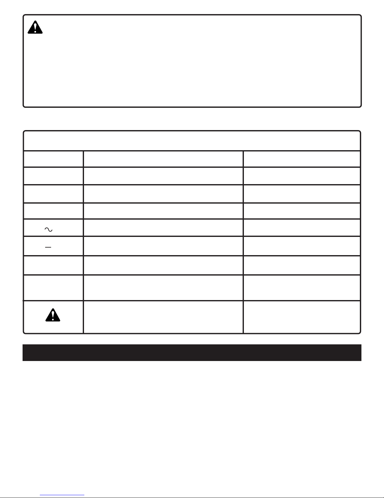
SPECIFIC SAFETY RULES AND/OR SYMBOLS
Hold tool by insulated gripping surfaces when performing an operation where the cutting tool may contact hidden
wiring. Contact with a "live" wire will make exposed metal parts of the tool "live" and shock the operator.
not using your battery tool or when changing acces-
sories. Following this rule will reduce the risk of electric
shock, fire, or serious personal injury.
■Do not place battery tools or their batteries near fire
or heat. This will reduce the risk of explosion and
possible injury.
■Do not charge battery tool in a damp or wet location.
Following this rule will reduce the risk of electric shock.
■For best results, your battery tool should be charged
in a location where the temperature is between 10
and 37 C.
C
■Under extreme usage or temperature conditions,
battery leakage may occur. If liquid comes in contact
with your skin, wash immediately with soap and
water, then neutralize with lemon juice or vinegar. If
liquid gets into your eyes, flush them with clean
water for at least 10 minutes, then seek immediate
medical attention. Following this rule will reduce the
risk of serious personal injury.
GENERAL SAFETY RULES