Ryobi AC053N1FH User manual

WARNING:
To reduce the risk of injury, user must read and understand the op-
erator’s manual for their string trimmer before using this accessory.
Always wear eye protection with side shields marked to comply
with Z87.1 along with hearing protection. Ensure compatibility and
proper fit before using this accessory. Stop the string trimmer and
remove battery pack or disconnect spark plug wire before changing
or adjusting accessories.
WARNING:
Do not use this accessory if a part is damaged or missing. If you are
not comfortable performing any of the functions described in these
instructions, take your unit to an authorized service center. Use of
a trimmer head that has been improperly assembled could cause
the trimmer head to come apart and/or detach from your trimmer
and result in serious personal injury and/or property damage.
PACKING LIST
See Figures 1 - 2.
Trimmer Head Assembly, Spacer, Silver Bolt, Black Bolt, Silver Nut,
Black Nut, 0.095 in. Pre-cut Line, Locking Pin, Washer, and Operator’s
Manual
INSTALLING TRIMMER HEAD
See Figures 1 - 7.
The Fixed Line/Bladed Trimmer Head installs differently on different
string trimmer attachments. Assembly instructions will vary based
on the style and type of attachment you have. See figures 3 and 4
to determine if you have a curved shaft or straight shaft attachment
and if your attachment comes with or without an arbor. Refer to
the Installation Chart to determine the appropriate items for your
attachment. Be sure to follow the instructions for your attachment
style and type.
NOTE: If you cannot identify the style and type of attachment you
have, contact customer service for assistance.
Stop the engine or motor, disconnect the spark plug wire for gas
power heads, remove the battery pack for cordless power heads,
or disconnect the plug from the power source for electric power
heads.
Remove the trimmer head housing by rotating the lower housing
counterclockwise so the arrow on the upper housing aligns with
the post on the lower housing.
Separate the upper housing from lower housing and set aside.
Locate the bolt or nut, and/or spacer required to install the trimmer
head to your attachment. Refer to the Installation Chart for details.
INSTALLATION CHART
If the trimmer head does not fit with any of the adaptors or
hardware supplied, contact Customer Service at 1-800-860-4050
for assistance.
Style Type Items Needed for Installation
Curved
Shaft With
Arbor Spacer, Upper Housing, Lower
Housing,Washer, and Black Bolt
Curved
Shaft Without
Arbor Upper Housing, Silver Nut, and Lower Housing
Straight
Shaft With
Arbor Spacer, Upper Housing, Lower
Housing,Washer, and Silver Bolt
Straight
Shaft Without
Arbor Upper Housing, Black Nut, and Lower Housing
FIXED LINE/BLADED
TRIMMER HEAD
AC053N1FH
Fig. 3
Fig. 4
Fig. 1
Fig. 2
STRAIGHT
SHAFT
UPPER
HOUSING
LOWER
HOUSING
SILVER
BOLT SILVER
NUT
LOCKING
PIN
BLACK
NUT WASHER
BLACK
BOLT
CURVED
SHAFT
CURVED SHAFTS STRAIGHT SHAFTS
ARBOR
ARBOR
SPACER
995000955
8-12-19 (REV:01)

For units with arbors:
Install the spacer onto the upper housing.
Slide the spacer and upper housing onto the arbor.
NOTE: The arbor will perforate the label on the bottom of the lower
housing. This will allow the arbor to insert through the unit.
NOTICE:
Make sure the arbor is fully seated into the hex-shaped pocket on
the spacer before proceeding. An arbor that is not fully seated will
cause damage to the upper housing and spacer.
Secure the trimmer head in place by installing a bolt (M8) through
the washer and into the opening in the arbor.
For curved shaft models, install the black bolt and turn clockwise.
Make sure bolt is fully screwed into arbor. Do not overtighten.
For straight shaft models, install the silver bolt and turn coun-
terclockwise. Make sure bolt is fully screwed into arbor. Do not
overtighten.
Install line as described in Installing Line.
For units without arbors:
Insert nut (M8), with flange facing down, into the hex pocket in the
upper housing then twist upper housing onto the attachment (see
figure 6).
For curved shaft models, insert silver nut and turn upper housing
clockwise.
For straight shaft models, insert black nut and turn upper housing
counterclockwise. If necessary, use a wrench (not provided) or
locking pin to hold the flange washer while tightening the upper
housing.
Slide lower housing onto the upper housing. Push together until the
arrows in the upper housing align to the posts in the lower housing.
Push and turn clockwise to the locked position.
To replace blades in the fixed line/blade housing:
Remove the fixed line/blade housing by rotating the lower housing
counterclockwise so the posts and the arrows on the upper housing
align, then pull the lower housing away from the upper housing.
NOTE: Remove the bolt before rotating housings apart on units
that have an arbor.
Remove the used blades and discard.
Install the new blades, making sure they are fully seated.
Reinstall the fixed line/blade housing as previously described.
Install line as described in Installing Line.
INSTALLING LINE
See Figure 8.
NOTE: Do not attempt to install line and blades in the fixed line/blade
housing at the same time.
Stop the engine or motor, disconnect the spark plug wire for gas
power heads, remove the battery pack for cordless power heads,
or disconnect the plug from the power source for electric power
heads.
Remove the blades by rotating the lower housing counterclockwise
so the arrow on the upper housing aligns with the posts on the
lower housing.
NOTE: Remove the bolt before rotating housings apart on units
that have an arbor.
Separate the lower housing from upper housing and set aside.
NOTE: It is not necessary to remove the upper string head housing
from the drive shaft.
Remove the blades and store for future use.
Fold a piece of 11 in. line in half so each half is equal in length.
NOTE: Some precut .095 in. lines are included with this kit.
Insert the ends of the line through the eyelets in the post and pull
tight.
Repeat with the other post.
The fixed line/blade housing is now ready to use.
CURVED SHAFT
CURVED SHAFT
STRAIGHT SHAFT
STRAIGHT SHAFT
UPPER
HOUSING
LOCKING
PIN
LOWER
HOUSING
SILVER
NUT
Fig. 5
Fig. 6
Fig. 7
ARBOR
UPPER
HOUSING
LOWER
HOUSING
BLACK
BOLT
WASHER WASHER
SPACER
ARBOR
UPPER
HOUSING
LOWER
HOUSING
SILVER
BOLT
SPACER
UPPER
HOUSING
LOWER
HOUSING
BLACK
NUT
Fig. 7
EYELET
POST LINE

TÊTE POUR TAILLE-BORDURE
À FIL FIXE/À LAME
AC053N1FH
AVERTISSEMENT :
Pour réduire les risques de blessure, l’utilisateur doit lire et comprendre
le manuel d’utilisation de son taille-bordures avant d’employer cet
accessoire. Toujours porter une protection oculaire certifiée conforme
à la norme ANSI Z87.1 ainsi qu’un protection auditive. S’assurer que
l’accessoire est compatible et qu’il est bien installé avant de l’utiliser.
Éteindre le taille-bordures et retirer le bloc-piles ou débrancher le fil de
bougie avant de changer ou d’ajuster un accessoire.
AVERTISSEMENT :
Ne pas utiliser cet accessoire si des pièces sont endommagées ou
manquantes. Si vous n’êtes pas à l’aise pour effectuer l’une ou l’autre
des tâches décrites dans les présentes instructions, confiez l’unité à un
centre de réparations agréé. Une tête de taille-bordures qui a été mal
assemblée pourrait se disloquer et/ou se détacher lors de l’utilisation
et causer des blessures graves et/ou des dommages à la propriété.
LISTE DE CONTRÔLE D’EXPÉDITION
Voir les figures 1 et 2.
Ensemble de tête de coupe à ligne, entretoise, boulon argentée, boulon
noir, écrou argentée, écrou noir, fil pré-coupé de 2,4 mm (0,095 po), goupille
de verrouillage, rondelle et manuel d’utilisation
INSTALLATION DU TÊTE DE COUPE
Voir les figures 1 à 7.
La tête pour taille-bordure à fil fixe/à lame s’installe différemment sur les
diverses accessoires de taille-bordure. Les instructions de montage varient
selon le style et le type de support de fixation que vous avez. Voir les figures
3 et 4 pour déterminer si vous avez un support de fixation à arbre droit ou
courbé et si votre support de fixation est doté d’un axe. Reportez-vous au
Schéma d’Installation pour déterminer les éléments appropriés pour votre
support de fixation. Assurez-vous de suivre les instructions correspondant
au style et au type de votre support de fixation.
NOTE : Si vous ne parvenez pas à identifier le style et le type de support
de fixation que vous avez, communiquez avec le service à la clientèle
pour obtenir de l’aide.
Arrêter le moteur, déconnecter le câble de bougie pour les têtes à
essence, retirer le bloc-piles pour les têtes électriques sans fil ou
débrancherlaprisedelasourced’alimentationpourlestêtesélectriques.
Enlever le boîtier de la tête à taille-bordures en tournant la partie
inférieure du boîtier dans le sens anti-horaire pour que la flêche sur
la partie supérieure du boîtier s’aligne avec la flèche extérieure sur le
boîtier de l’alimentation par chocs.
Tirer le boîtier inférieur loin du boîtier supérieur et mettre de côté.
Localisez le boulon ou l’écrou, le guide de ligne, et/ou l’entretoise
nécessaire pour l’installation de la tête du taille-bordures à votre sup-
port de fixation. Reportez-vous au Schéma d’Installation pour plus
de détails.
SCHÉMA D’INSTALLATION
Si la tête du taille-bordures n’est pas compatible avec l’un des
adaptateurs ou le matériel fourni, communiquez avec le Service à
la clientèle au 1-800-860-4050 pour obtenir de l’aide.
Style Type Éléments nécessaires pour l’installation
Arbre
courbé Avec
axe Entretoise, boîtier supérieur, boîtier
inférieur, rondelle et boulon noir
Arbre
courbé Sans
axe Boîtier supérieur, écrou argentée
et boîtier inférieur
Arbre
droit Avec
axe Entretoise, boîtier supérieur, boîtier
inférieur, rondelle et boulon argentée
Arbre
droit Sans
axe Boîtier supérieur, écrou noir et boîtier inférieur
ARBRE
DROIT
BOULON
ARGENTÉE
ÉCROU
ARGENTÉE
ÉCROU
NOIR
BOULON
NOIR
ARBRE COURBÉE ARBRE DROIT
AXE
AXE
ENTRETOISE
GOUPILLE DE
VERROUILLAGE
Fig. 3
Fig. 4
Fig. 1
Fig. 2
BOÎTIER
SUPÉRIEUR
BOÎTIER
INFÉRIEUR
ARBRE
COURBÉE
RONDELLE

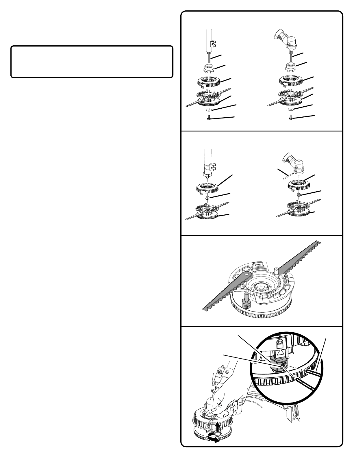
Pour les unités équipées d’un axe :
Installez l’entretoise sur la section du boîtier supérieur.
Glissez l’entretoise et la section du boîtier supérieur sur l’axe.
NOTE : L’axe perforera l’étiquette sur la partie inférieure du boîtier.
Ceci permettra d’insérer l’axe à travers l’unité.
AVIS :
S’assurer que l’axe est correctement inséré dans le logement hexag-
onal de l’entretoise avant de procéder. Si l’axe n’est pas correctement
inséré, ceci pourrait causer des dommages au boîtier et à l’entretoise.
Fixer la tête pour taille-bordure en place en installant un boulon (M8)
dans la rondelle et dans l’ouverture de l’arbre.
Installezle boulon noir et tournez dans lesens horairepourlesmodèles
à arbre courbé. Assurez-vous que le boulon est complètement vissé
dans l’axe. No serrez pas trop.
Installez le boulon argenté et tournez dans le sens antihoraire pour les
modèles à arbre droit. Assurez-vous que le boulon est complètement
vissé dans l’axe. No serrez pas trop.
Installer le fil comme décrit au chapitre Installation du fil.
Pour les unités qui ne sont pas équipées d’un axe :
Insérezleécrou(M8),avecflasquetournée versle bas, dans lelogement
de la section du boîtier supérieur puis tournez la section du boîtier
supérieur sur le support de fixation (voir la figure 6).
Insérez le écrou argenté et tournez la section du boîtier supérieur dans
le sens horaire pour les modèles à arbre courbé.
Insérez le écrou noir et tournez la section du boîtier supérieur dans le
sens antihoraire pour les modèles à arbre droit. Si nécessaire, utilisez
une clé (non fournie) ou une goupille de verrouillage pour maintenir la
rondelle bombée lors du serrage de la partie supérieure du boîtier.
Glissez la section du boîtier inférieur sur la section du boîtier supérieur.
Pousser ensemble jusqu’à ce que les flèches du boîtier supérieur
s’alignent avec les flèches du boîtier inférieur. Pousser et tourner dans
les sens horaire vers la position verrouillée.
Pour remplacer les lames dans le boîtier de fil/lame fixe :
Enlever le boîtier de fil/lame fixe en tournant le boîtier inférieur dans
le sens antihoraire, de sorte à aligner les montants et les flèches du
boîtier supérieur, puis tirer le boîtier inférieur loin du boîtier supérieur.
NOTE : Pour les unités comportant un arbre, enlever le boulon avant
de tourner les logements pour les séparer.
Retirer les lames usées et les jeter.
Installer les nouvelles lames, en veillant à les mettre complètement en
position.
Installer de nouveau le boîtier de fil/lame fixe comme il est décrit
précédemment.
Installer le ligne tel que décrit à la section intitulée Installation du fil.
INSTALLATION DU FIL
Voir la figure 8.
NOTE : Ne pas tenter d’installer le fil et les lames dans le boîtier de fil/
lame fixe en même temps.
Arrêter le moteur, déconnecter le câble de bougie pour les têtes à
essence, retirer le bloc-piles pour les têtes électriques sans fil ou
débrancherlaprisedelasourced’alimentationpourlestêtesélectriques.
Enlever le boîtier de fil/lame fixe en tournant le boîtier inférieur dans
le sens antihoraire, de sorte à aligner les montants et les flèches du
boîtier supérieur.
NOTE : Pour les unités comportant un arbre, enlever le boulon avant
de tourner les logements pour les séparer.
Tirer le boîtier inférieur loin du boîtier supérieur et mettre de côté.
NOTE : Il n’est pas nécessaire de retirer le boîtier supérieur de tête de
coupe hors de l’arbre d’entraînement.
Enleverles lames et ranger l’appareil de manièrepour un usage ultérieur.
Plier un morceau de fil de 280 mm (11 po) en deux pour que les deux
moitiés soient égales.
NOTE :Cetensemblecontientdufils de 2,41 mm (0,095 po) pré-coupés.
Insérer les bouts du fil dans les œillets du montant et tirer fermement.
Répéter pour l’autre poteau.
Le boîtier de fil/lame fixe est maintenant prêt à être utilisé.
ARBRE COURBÉE
ARBRE COURBÉE
ARBRE DROIT
ARBRE DROIT
AXE
ENTRETOISE
BOÎTIER
SUPÉRIEUR
BOULON
NOIR
BOÎTIER
INFÉRIEUR
BOÎTIER
SUPÉRIEUR
BOÎTIER
SUPÉRIEUR
ÉCROU
ARGENTÉE
ÉCROU
NOIR
BOÎTIER
INFÉRIEUR
BOÎTIER
INFÉRIEUR
AXE
ENTRETOISE
BOÎTIER
SUPÉRIEUR
BOULON
ARGENTÉE
BOÎTIER
INFÉRIEUR
GOUPILLE DE
VERROUILLAGE
Fig. 5
Fig. 6
Fig. 8
Fig. 7
ŒILLET
POTEAU LIGNE
RONDELLE RONDELLE

CABEZAL RECORTADORA DE LÍNEA
FIJA/CON HOJAS
AC053N1FH
ADVERTENCIA:
Para reducir el riesgo de lesiones, el usuario debe leer y comprender
el manual del operador de la recortadora de hilo antes de usar este
accesorio. Siempre póngase protección ocular con la marca de
cumplimiento de la norma ANSI Z87.1 junto con protección auditiva.
Asegúrese de que sea compatible con el producto antes de utilizar
este accesorio. Apague la recortadora de hilo y retire el paquete de
baterías o desconecte el cable de la bujía antes de cambiar o ajustar
los accesorios.
ADVERTENCIA:
No utilice este accesorio si tiene una pieza dañada o faltante. Si no
se siente preparado para realizar alguna de las funciones que se
describen en estas instrucciones, lleve la unidad a un centro de servicio
autorizado. Si usa un cabezal de recortadora ensamblado de forma
inapropiada, este podría desconectarse de la recortadora y causar
lesiones personales o daños en la propiedad severos.
LISTA DE EMPAQUETADO
Vea las figuras 1 y 2.
Conjunto de cabezal de la recortadora, separador, perno plata, perno
negro, tuerca plata, tuerca negro, guía de hilo negra, guía de hilo blanca,
Línea precortada de 2,4 mm (0,095 pulg.), pasador de fijación, arandela
y manual del operador
INSTALACIÓN DE CABEZAL DE LA RECORTADORA
Vea las figuras 1 a 7.
El cabezal de recortadora de línea fija/con hojas se instala de manera
diferente en distintos accesorios para recortadora de hilo. Las instrucciones
de ensamblaje varían en función del estilo y el tipo de conexión que usted
tenga. Consulte las figuras 3 y 4 para determinar si tiene una conexión
de eje curvo o recto, y si la conexión viene o no con un árbol. Consulte el
Gráfico de Instalación para determinar los elementos apropiados para
su conexión. Asegúrese de seguir las instrucciones para el estilo y tipo
de conexión que tenga.
NOTA: Si no puede identificar el estilo y tipo de conexión que tiene,
comuníquese con el Servicio de atención al cliente.
Detenga el motor, desconecte el cable de la bujía de los cabezales
de alimentación a gasolina, extraiga la batería de los cabezales de
alimentación inalámbricos o desconecte el enchufe de la fuente de
alimentación de los cabezales de alimentación eléctrica.
Retire la carcasa del cabezal de recortadora girando la carcasa inferior
hacia la izquierda de modo que la flecha de la carcasa superior quede
alineada con la flecha exterior de la carcasa.
Separe la carcasa inferior en la carcasa superior y colóquela a un lado.
Busque el tornillo o la tuerca, la guía de línea o el separador requeridos
para instalar el cabezal de la recortadora a la conexión. Consulte el
Gráfico de Instalación para obtener detalles.
GRÁFICO DE INSTALACIÓN
Si el cabezal de la recortadora no encaja con ninguno de los
adaptadores o las herramientas suministrados, comuníquese con
Servicio al cliente al 1-800-860-4050 para recibir asistencia.
Estilo Tipo Elementos necesarios para la instalación
Eje
curvo
Con
árbol
Separador, armazón superior,
armazón inferior, arandela y perno negro
Eje
curvo
Sin
árbol Armazón superior, tuerca plata y armazón inferior
Eje
recto
Con
árbol
Separador, armazón superior,
armazón inferior, arandela y perno plata
Eje
recto
Sin
árbol Armazón superior, tuerca negro y armazón inferior
Fig. 3
Fig. 4
EJE CURVO EJE RECTO
ÁRBOL
ÁRBOL
PERNO
PLATA
TUERCA
PLATA
TUERCA
NEGRO
PERNO
NEGRO
SEPARADOR
PASADOR DE
FIJACIÓN
Fig. 1
Fig. 2
ARMAZÓN
SUPERIOR
ARMAZÓN
INFERIOR
EJE
RECTO
EJE
CURVO
RONDELLE

EJE CURVO
ARBRE COURBÉE ARBRE DROIT
Fig. 5
Fig. 6
Fig. 7
OJILLOS
POSTE LÍNEA
Para las unidades con árboles:
Instale el separador en el armazón superior.
Deslice el separador y el armazón superior en el árbol.
NOTA: El árbol perforará la etiqueta de la parte inferior de la carcasa
inferior. Esto permite insertar el árbol en la unidad.
AVISO:
Asegúrese de que el árbol esté bien colocado en el compartimento
hexagonal del separador antes de continuar. Si el árbol no está bien
colocado, el armazón superior y el separador se dañarán.
Asegure el cabezal de recortadora en su lugar con un perno (M8) a través
de la arandela y en la abertura del árbol.
Instale el perno negro y gire en sentido horario para los modelos de
eje curvo. Asegúrese de que el perno esté completamente enroscado
en el árbol. No apriete demasiado.
Instale el perno plateado y gire en sentido antihorario para los modelos
de eje recto. Asegúrese de que el perno esté completamente enroscado
en el árbol. No apriete demasiado.
Instale la línea como se indica en Instalación de la línea.
Para las unidades sin árboles:
Inserte una tuerca (M8), con brida hacia abajo, en el hueco del armazón
superior y luego gire el armazón superior en la conexión (vea la figura 6).
Inserte una tuerca plateada y gire el armazón superior en sentido horario
para los modelos de eje curvo.
Inserte una tuerca negra y gire el armazón superior en sentido antihorario
para los modelos de eje recto. Si es necesario, use una llave (no
proporcionada) o un pasador de bloqueo para sostener la arandela de
brida mientras ajusta el armazón superior.
Deslice la carcasa inferior en la carcasa superior. Empuje ambas piezas
para unirlas hasta que las flechas de la carcasa superior se alineen con
las flechas de la carcasa inferior. Empuje y gire hacia la derecha a la
posición bloqueada.
Para reemplazar las hojas en la carcasa de línea fija/hoja:
Retire la carcasa de línea fija/hoja girando la carcasa inferior hacia la
izquierda para que los pernos y las flechas del alojamiento superior
queden alineados; luego, retire la carcasa inferior de la carcasa superior.
NOTA: Retire el perno antes de girar y retirar las carcasas en unidades
con árbol.
Retire las hojas usadas y deséchelas.
Instale las hojas nuevas, asegurándose de que queden bien colocadas.
Vuelva a colocar la carcasa de línea fija/hoja como se describió anterior-
mente.
Instale la línea como se indica en Instalación de la línea.
INSTALACIÓN DE LA LÍNEA
Vea la figura 8.
NOTA: No intente instalar la línea y las hojas en la carcasa de línea fija/hoja
al mismo tiempo.
Detenga el motor, desconecte el cable de la bujía de los cabezales
de alimentación a gasolina, extraiga la batería de los cabezales de
alimentación inalámbricos o desconecte el enchufe de la fuente de
alimentación de los cabezales de alimentación eléctrica.
Retire la carcasa de línea fija/hoja girando la carcasa inferior hacia la
izquierda para que los pernos y las flechas del alojamiento superior
queden alineados.
NOTA: Retire el perno antes de girar y retirar las carcasas en unidades
con árbol.
Separe la carcasa inferior en la carcasa superior y colóquela a un lado.
NOTA: No es necesario retirar la carcasa del cabezal de hilo superior de
la barra de transmisión.
Retire las hojas y guárdelas para usarlas en el futuro.
Doble un pedazo de línea de 279,40 mm (11 pulg.) en dos de modo que
ambos lados tengan la misma longitud.
NOTA: Algunos trozos precortados de 2,41 mm (0,095 pulg.) se incluyen
con el kit.
Inserte los extremos de línea en los orificios del poste y tire para ajustar.
Repita el proceso con el otro perno.
La carcasa de línea fija/hoja ahora está lista para usarse.
EJE RECTO
ARMAZÓN
SUPERIOR
ARMAZÓN
SUPERIOR
TUERCA
NEGRO
ÁRBOL ÁRBOL
SEPARADOR SEPARADOR
ARMAZÓN
SUPERIOR
ARMAZÓN
SUPERIOR
PERNO
PLATA
PERNO
NEGRO
ARMAZÓN
INFERIOR
ARMAZÓN
INFERIOR
TUERCA
PLATA
ARMAZÓN
INFERIOR
ARMAZÓN
INFERIOR
PASADOR DE
FIJACIÓN
Fig. 8
ARANDELA ARANDELA
Table of contents
Languages:
Other Ryobi Garden Machinery Accessories manuals

Ryobi
Ryobi RY41135 User manual

Ryobi
Ryobi EXPAND-IT RYSST44VN User manual

Ryobi
Ryobi EXPAND-IT RYBRC77VN User manual

Ryobi
Ryobi EXPAND-IT ALT04G User manual

Ryobi
Ryobi Expand-It RYBRC77 User manual

Ryobi
Ryobi RY15527 User manual

Ryobi
Ryobi Expand-It RY15523A User manual

Ryobi
Ryobi AC053N1BFH User manual

Ryobi
Ryobi Expand-It AJB01 User manual

Ryobi
Ryobi EXPAND-IT RY15526 User manual