Ryobi PLT3043E, RY70103 User manual

OPERATOR’S MANUAL
Trimmer
PLT3043E
RY70103
YournewtrimmerhasbeenengineeredandmanufacturedtoRyobi’shighstandardfordependability,easeofoperationandoperator
safety.Properly cared for, it will give you years of rugged, trouble-free performance.
Thank you for buying a Ryobi trimmer.
SAVE THIS MANUALFOR FUTURE REFERENCE
WARNING: To reduce the risk of injury, the user must read and understand the operator’s manual.

2
TABLE OF CONTENTS
■■
■■
■Safety.....................................................................................................................................................................2 - 3
■■
■■
■Symbols .................................................................................................................................................................4 - 5
■■
■■
■TechnicalData ............................................................................................................................................................. 5
■■
■■
■Unpacking ................................................................................................................................................................... 6
■■
■■
■Features ...................................................................................................................................................................... 6
■■
■■
■Assembly ...............................................................................................................................................................7 - 8
■■
■■
■Operation.............................................................................................................................................................. 9 - 11
■■
■■
■Maintenance ....................................................................................................................................................... 12 - 14
■■
■■
■Troubleshooting................................................................................................................................................... 15 - 16
■■
■■
■Warranty .................................................................................................................................................................... 17
■■
■■
■Safety Directive......................................................................................................................................................... 17
SAFETY
WARNING:
Do not attempt to operate this trimmer until you have read thoroughly and understand completely all instructions,
safety rules etc contained in this manual. Failure to comply may result in accidents involving fire, electric shock or
serious personal injury. Save operator’s manual and review frequently for continuing safe operation, and instructing
others who may use this tool.
READ ALL INSTRUCTIONS
GENERAL SAFETY RULES
■Forsafe operation,readandunderstand allinstructions
before using the trimmer. Follow all safety instructions.
Failure to follow all safety instructions listed below may
result in serious personal injury.
■Donot allow children oruntrained individuals touse
this unit.
■■
■■
■Never start or run the engine in a closed or poorly
ventilated area; breathing exhaust fumes can kill.
■■
■■
■Clear the work area before each use. Remove all objects
such as stones, broken glass, nails, wire or string which
maybe thrown orbecome entangled inthe string head.
■■
■■
■Wearfulleyeandhearingprotectionwhileoperating
this unit.
■■
■■
■Wear heavy long trousers, boots and gloves. Do not
wear loose-fitting clothing, shorts, jewellery of any kind,
orgobarefoot.

3
SAFETY
■■
■■
■Secure long hair so it is above shoulder level to prevent
entanglementin any moving parts.
■■
■■
■Keep all bystanders, children and pets at least 15 m
(50 ft) away.
■■
■■
■Do not operate this unit when you are tired, ill or under
the influence of alcohol, drugs or medication.
■■
■■
■Donotoperate in poor lighting.
■■
■■
■Keepfirm footing and balance.Do not overreach.
Overreaching may result in loss of balance or exposure
to hot surfaces.
■■
■■
■Keep all parts of your body away from any moving part.
■■
■■
■Do not touch areas around the silencer or cylinder of the
trimmer: these parts get hot from operation.
■■
■■
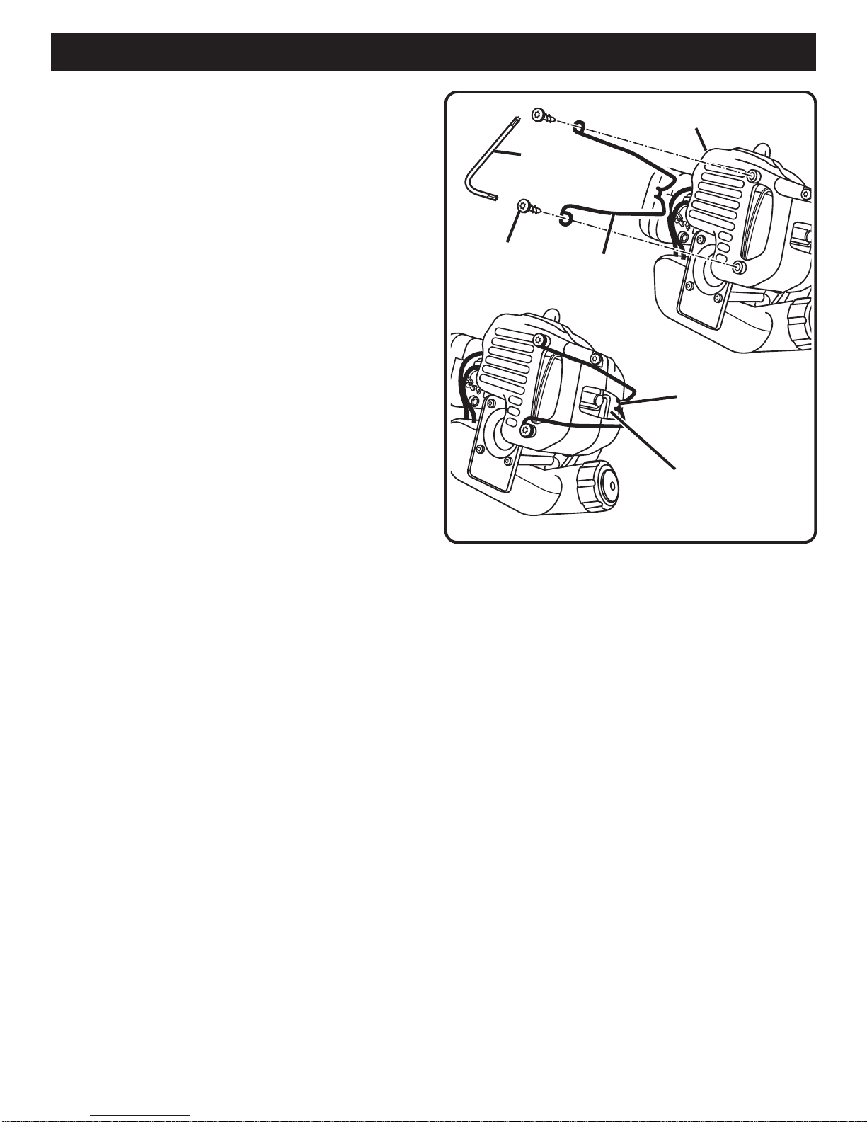
■Always stop the engine and remove the sparking plug
wirebefore making any adjustments orrepairs, except
forcarburettoradjustments.
■■
■■
■Inspect the unit before each use for loose fasteners,
fuel leaks etc. Replace any damaged parts before use.
■■
■■
■Thestringheadwillrotateduringcarburettoradjust-
ments.
■■
■■
■Ithas been reported that vibrations from hand-heldtools
may contribute to a condition called Raynaud’s Syn-
drome in certain individuals. Symptoms may include
tingling, numbness and blanching of the fingers, usually
apparentuponexposuretocold.Hereditaryfactors,
exposure to cold and dampness, diet, smoking and work
practices are all thought to contribute to the develop-
ment of these symptoms. It is not known at present
what, if any, vibrations or extent of exposure may
contribute to the condition. There are measures that can
be taken by the operator to possibly reduce the effects
ofvibration:
a) Keep yourbodywarm incoldweather. Whenoperat-
ing the unit wear gloves to keep the hands and wrists
warm. It is reported that cold weather is a major
factorcontributingtoRaynaud’s Syndrome.
b) After each period of operation, exercise to increase
bloodcirculation.
c) Take frequent work breaks. Limit the amount of
exposureperday.
d) Keepthe tool well maintained, fasteners tightened
andwornpartsreplaced.
If you experience any of the symptoms of this condition,
immediately discontinue use and see your doctor about
these symptoms.
■■
■■
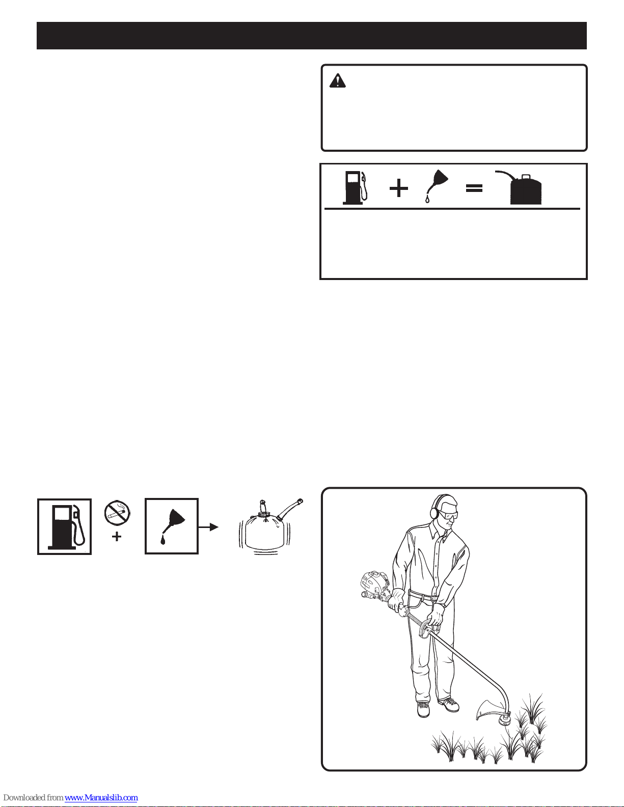
■Mix and store fuel in a container approved for petrol.
■■
■■
■Mix fuel outdoors where there are no sparks or flames.
Wipe up any fuel spillage. Move 9 m (30 ft) away from
refuellingsitebeforestartingengine.
■■
■■
■Stopthe engine andallow to coolbefore refuelling or
storing the unit.
■■
■■
■Allow the engine to cool; empty the fuel tank and secure
the unit from moving before transporting in a vehicle.
SPECIFIC SAFETY RULES FOR TRIMMER USE
■■
■■
■Replacestring head ifcracked, chipped or damaged in
any way. Be sure the string head is properly installed
and securely fastened. Failure to do so may cause
seriousinjury.
■■
■■
■Make sure all guards, straps, deflectors and handles are
properlyandsecurelyattached.
■■
■■
■Use only the manufacturer’s replacement string in the
cutting head. Do not use any other cutting attachment.
■■
■■
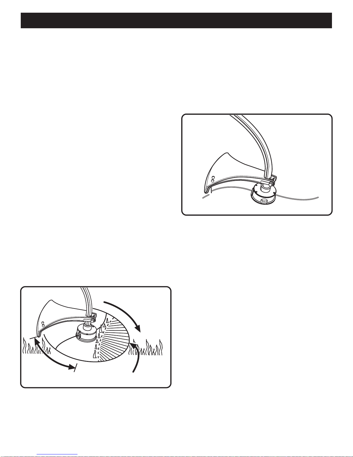
■Never operate unit without the grass deflector in place
andin goodcondition.
■■
■■
■Maintaina firmgrip onboth handles while trimming.Keep
string head below waist level. Never cut with the string
head located over 76 cm (30 in) or more above
theground.

4
SYMBOLS
Important:Someofthefollowingsymbolsmaybeusedonyourtool.Pleasestudythemandlearntheirmeaning.Proper
interpretation of these symbols will allow you to operate the tool better and more safely.
SYMBOL NAME EXPLANATION
Safety Alert Symbol Indicates danger, warning or caution. It means
attention!!! Your safety is involved.
ReadYourOperator’sManual Your manual contains special messages to bring
attention to potential safety concerns as well as
operatingandservicinginformation.Pleasereadall
the information carefully to ensure satisfaction and
safe use.
Weareyeandhearingprotection Weareyeandhearingprotectionwhenoperatingthis
equipment.
Keepbystandersaway Keep all bystanders at least 15 m (50 ft) away.
Ricochet DangerofRicochet.
Noblade Do not install any type of blade on this unit.
RPMDecal Rotational direction and maximum speed of the shaft
for the cutting attachment.
Boots Wearnon-slip safety footwearwhen using this
equipment.
Gloves Wearnon-slip,heavy-dutygloves.
NoSmoking Do not smoke when mixing fuel or filling fuel tank.
Petrol Useunleaded petrol intended formotorvehicleuse
with an octane rating of 87 ([R + M] / 2) or higher.
Oil Use 2-cycle oil for air cooled engines.
Mix Petrol and Oil Mix the fuel mix thoroughly and also each time before
fuelling.
Switch On/Off Switch
I = ON to Run
O = OFF to Stop
min-1
9,000

5
Thepurpose of safety symbols is to attract yourattention to possible dangers. The safety symbols, and the explanations
with them, deserve your careful attention and understanding. The safety warnings do not by themselves eliminate any
danger. The instructions or warnings they give are not substitutes for proper accident prevention measures.
SYMBOL MEANING
DANGER: Indicates an imminently hazardous situation which, if not avoided, will result in death or
seriousinjury.
WARNING: Indicates a potentially hazardous situation which, if not avoided, could result in
seriousinjury.
CAUTION: Indicates a potentially hazardous situation which, if not avoided, may result in minor or
moderate injury. It may also be used to alert against unsafe practices which may cause property damage.
NOTE: Advises you of information or instructions vital to the operation or maintenance of the equipment.
SAVE THESE INSTRUCTIONS
TECHNICAL DATA
Weight Without fuel and string head ................................................................................................................4.69 Kg
Without fuel, w/string head ..................................................................................................................5.08 Kg
Fuel tank volume ................................................................................................................................................... 42.5cm3
Cuttingswath.......................................................................................................................................................... 433mm
Enginedisplacement ................................................................................................................................................ 30 cm3
Maximumengineperformance(inaccordancewithISO8893) ............................................................................... 0.78kW
Maximum rotational frequency of the spindle .................................................................................................... 9,000/min-1
EngineSpeed(rotationalfrequency)atrecommendedmax.spindlerotationalfrequency.................................12,500/min-1
Enginespeed(rotationalfrequency) atidle .............................................................................................2,000-2,500/min-1
Fuelconsumption (in accordancewith ISO 8893) at max. engine performance................................................... 0.52 kg/h
Specific fuel consumption (in accordance with ISO 8893) at max. engine performance ...................................... 0.47 kg/h
Vibrationlevelidling FrontHandle ......................................................................................................................... 5.9
RearHandle .......................................................................................................................... 3.7
Vibrationlevelracing FrontHandle ......................................................................................................................... 8.2
RearHandle .......................................................................................................................... 8.6
Soundpressurelevel (in accordance with EN ISO 11806:1997, ISO7917:1987) .......................................................... 102
Soundpower level (inaccordancewithISO 10884) ....................................................................................................... 113
SYMBOLS

6
FEATURES
Fig. 1
STARTER GRIP
ENGINE HOUSING
THROTTLE TRIGGER
FRONT HANDLE
GRASS DEFLECTOR
CUTTING
LINE
IGNITION
SWITCH
THROTTLE
INTERLOCK
SHAFT
UNPACKING
INSTRUCTIONS
■■
■■
■Carefullyremove the productfrom the carton.
■■
■■
■Inspect the product to make sure no breakage or
damageoccurredduringcarriage.
■■
■■
■Do not discard the packing material until you have
inspectedandoperatedtheproduct.
PACKING LIST FOR OWNER’S KIT
■■
■■
■Grassdeflector
■■
■■
■Fronthandle
■■
■■
■Silencerguard,torquewrenchandscrews
■■
■■
■Fixings
■■
■■
■Operator’smanual

7
ASSEMBLY INSTRUCTIONS:
GRASS DEFLECTOR
See Figure 2.
1. Remove wing nut, flat washer, lock washer and bolt
from the Owner’s Kit.
2. Place grass deflector over shaft and bracket.
3. Install bolt through the slots in the tabs on grass
deflector and bracket on drive shaft housing.
4. Install flat washer, lock washer and wing nut.
5. TightenSecurely.
ASSEMBLY
FRONT HANDLE
See Figure 3.
1. Place the handle base and the bracket on the drive shaft
housingbelowthe spacer.
2. Install the two handle base screws and nuts, but do not
tightencompletely.
3. Place the handle grip onto the handle base and install the
two screws.Tighten securely.
4. Adjust the position of the handle for best balance
andcomfort.
5. Tighten the two handle base screws securely.
NOTE: Do not attempt to remove or modify the spacer.This
spacer limits the upper position of the handle grip.
See
Figure3.
GRASS DEFLECTOR
BRACKET
BOLT
FLAT WASHER
LOCK WASHER
WING NUT
Fig. 2
Fig. 3
HANDLE
BASE
HANDLE BASE
SCREWS
SPACER
SCREWS
BRACKET NUTS
HANDLE GRIP

8
Fig. 4
BENT END OF
SILENCER GUARD
OPENING IN REAR
HOUSING
SILENCER GUARD ASSEMBLY
See Figure 4.
1. Removesilencer guard and two screws from the
owner’s kit.
2. Attach the silencer guard to the rear housing.
NOTE: Make sure the bent end of the silencer guard fits
securely into the opening of the rear housing.
3. Using the torque wrench supplied, install the two screws
andtightensecurely.
ASSEMBLY
SCREWS SILENCER
GUARD
REAR HOUSING
TORQUE
WRENCH

9
FILLING THE TANK
1. Cleansurface around fuel cap to prevent contamination.
2. Loosen fuel cap slowly to release pressure and to keep
fuel from escaping around the cap.
3. Carefully pour fuel mixture into the tank. Avoid spillage.
4. Prior to replacing the fuel cap, clean and inspect
the gasket.
5. Immediately replace fuel cap and hand tighten. Wipe up
any fuel spillage. Move 9 m (30 ft) away from refuelling
sitebeforestartingengine.
NOTE: It is normal for smoke to be emitted from a new
engine during and after first use.
1 Litre + 20 ml =
2 Litres + 40 ml =
3 Litres + 60 ml =
4 Litres + 80 ml =
5 Litres + 100 ml = }50:1
WARNING
Always shut off engine before fuelling. Never add fuel
to a machine with a running or hot engine. Move at
least 9 m (30 ft) from refuelling site before starting
engine. Do not smoke!
OPERATION
OPERATING THE TRIMMER
SeeFigure 5.
Holdthe trimmer with the right hand onthe rear handle and
the left hand on the front handle.Keep a firm grip with both
handswhile in operation.Trimmer shouldbe held at a
comfortableposition withthe rear handle about hipheight.
Always operate trimmer at full throttle. Cut tall grass from
the top down.This will prevent grass from wrapping round
the drive shaft housing and string head which may cause
damagefromoverheating.Ifgrassbecomeswrappedround
the string head, stop the engine, disconnect the sparking
plug wire, and remove the grass.Prolonged cutting at partial
throttle will result in oil dripping from the silencer.
FUEL AND REFUELLING
HANDLING THE FUEL SAFELY
■■
■■
■Always handle fuel with care; it is highly flammable.
■■
■■
■Alwaysrefueloutdoors where there are no sparks and
flames. Do not inhale fuel vapour.
■■
■■
■Do not let petrol or oil come in contact with your skin.
■■
■■
■Keep petrol and oil away from the eyes. If petrol or oil
comes in contact with the eyes, wash them immediately
with clean water. If irritation is still present, see a doctor
immediately.
■■
■■
■Clean up spilled fuel immediately.
MIXING THE FUEL
■■
■■
■This product is powered by a 2-cycle engine and requires
pre-mixingpetroland2-cycleoil.Pre-mixunleadedpetrol
and2-cycle engine oil in a clean containerapproved
forpetrol.
■■
■■
■Thisengine is certified tooperate on unleaded petrol
intended for motor vehicle use with an octane rating of
87 ([R + M] / 2) or higher.
■■
■■
■Do not use any type of pre-mixed petrol/oil from fuel
service stations. This includes the pre-mixed petrol/oil
intended for use in mopeds, motorcycles etc.
■■
■■
■Use a high quality 2-cycle self-mixing oil for air-cooled
engines. Do not use motor vehicle oil or 2-cycle
outboardoil.
■■
■■
■Mix 2% oil into the petrol. This is a 50:1 ratio.
■■
■■
■Mix the fuel thoroughly and also each time before
refuelling.
■■
■■
■Mix in small quantities. Do not mix quantities larger than
are usable in a 30 day period. A 2-cycle oil containing a
fuelstabiliser is recommended.
Fig. 5

10
OPERATION
BEST CUTTING
AREA
DANGEROUS
CUTTING AREA Fig. 6
ADVANCING THE STRING
ADVANCING STRING USING THE EZ LINE™ TAP
ADVANCE SYSTEM
String advance is controlled by tapping string head on grass
whilerunning engine at full throttle.
1. Run engine at full throttle.
2. Tap string head on ground to advance string. String
advances each time the head is tapped.
3. Several taps may be required until string strikes the
cut-offblade.
4. Resumetrimming.
NOTE: If the string is worn too short you may not be able to
advance the string by tapping it on the ground.If so, STOP
THEENGINE, and manuallyadvance the string.
ADVANCING THE STRING MANUALLY
Pushthe spool retainerdown while pulling on string(s) to
manuallyadvance the string.
CUTTING TIPS
See Figure 6.
■Keep the trimmer tilted toward the area being cut; this is
the best cutting area.
■Do not cut in dangerous cutting area.
■Use the tip of string to do the cutting; do not force string
head into uncut grass.
■Wire and picket fences cause extra string wear, even
breakage. Stone and brick walls, kerbs and wood may
wearstringrapidly.
■Avoidtrees and shrubs. Tree bark, wood mouldings,
cladding and fence posts can easily be damaged by
the string.
GRASS DEFLECTOR LINE TRIMMING
CUT-OFF BLADE
See Figure 7.
This trimmer is equipped with a line trimming cut-off blade
on the grass deflector.For best cutting, advance string until
it is trimmed to length by the cut-off blade. Advance string
wheneveryouheartheenginerunningfaster than normal.
This will maintain best performance and keep string long
enoughtoadvanceproperly.
Fig. 7

11
OPERATION
WARNING
Never start or run the engine inside a closed or poorly
ventilated area; breathing exhaust fumes can kill.
TO START A COLD ENGINE:
1. Lay trimmer on a flat, bare surface.
2. Push primer bulb 8 to 10 times.
NOTE: Donotsqueezethe throttle triggerbeforeengine
starts.Squeezing the throttle trigger at this time will prevent
the unit from starting.
3. Move the lever to the “COLD START” position.
See
Figure9.
4. Pull the starter rope until engine runs.
5. Allow the engine to warm up for 4-10 seconds.
6. Depressthethrottle interlock, then squeezeand release
the throttle trigger. This allows the choke to automati-
cally set to the “WARM START” position. Your unit is
nowready for use.
NOTE: The lever will automatically set to the “WARM
START” position after the throttle trigger is squeezed for
the first time.
STARTING AND STOPPING
SeeFigures 8 and 9.
NOTE:Theunitisequippedwithanautomaticchokefeature.
Thestartinginstructionsforthisfeaturearedifferentfromunits
with a manual choke. Be sure to read and follow the starting
instructionsbelow.
TO START A WARM ENGINE:
1. Lay trimmer on a flat, bare surface.
2. Chokelevershouldalreadybe inthe“WARMSTART”
position. If not, squeeze and release throttle trigger.
Pull the starter rope until unit runs.
TO STOP THE ENGINE:
To stop the engine, depress the switch to the “O” position.
PRIMER BULB
LEVER Fig. 9
WARM START
POSITION
COLD START
POSITION
IGNITION SWITCH
I = ON TO RUN
O = OFF TO STOP
Fig. 8
THROTTLE
TRIGGER
THROTTLE INTERLOCK

12
■Youmay make adjustments andrepairs described here.
For other repairs, have the trimmer serviced by an
authorisedservicedealer.
■Consequencesofimpropermaintenancemayinclude
excess carbon deposits resulting in loss of performance
and discharge of black oily residue dripping from
the silencer.
■Make sure all guards, straps, deflectors and handles are
properly and securely attached to avoid the risk of
personalinjury.
SPOOL REPLACEMENT
EZ LINE™ TAP ADVANCE SYSTEM
NEW PRE-WOUND SPOOL
SeeFigures10and11.
If replacing string only, refer to “String Replacement” later in
this manual.
Use only 2.4 mm (.080 in.) diameter monofilament string.
Usethe manufacturer’s replacement string for best
performance.
1. Stop the engine, disconnect the sparking plug wire. Hold
thestringheadandunscrewthespoolretainer.Turn
anticlockwise.
2. Remove the empty spool from the string head. Keep the
spring attached to the spool.
3. To install the new spool, make sure the two strings are
captured in the slots opposite each other on the new
spool. Make sure the ends of each string are extended
approximately 152 mm (6 in) beyond each slot.
4. Thread the strings into the eyelets in the string head.
Carefully push the spool into the string head (gently pull
the strings to the outside if necessary). When the spool
is positioned in the string head, grasp the strings and
pull sharply to release them from the slots in the spool.
5. Push down and turn the spool anticlockwise until it no
longer turns. Hold the spool down and rotate clockwise
a small amount. Release the spool. The spool should be
locked down in the string head. If not, hold down and
rotate until locked.
MAINTENANCE
WARNING:
Useonlyoriginal manufacturer’s replacement parts,
accessories and attachments. Failure to do so can
cause possible injury, poor performance and may
voidyourwarranty.
EYELETS
SPRING
SLOTS
STRING HEAD
DRIVE SHAFT
Fig.10
Fig.11
EYELETS
SPOOL
RETAINER
SPOOL
6. Make sure the string head and the spool retainer are
installed on the drive shaft by turning the retainer
clockwise to tighten.
7. Pull the strings again to rotate the spool into cutting
position.Pushthe spool retainer downwhilepulling on
string(s) to manually advance the string and to check for
proper assembly of the string head.

13
STRING REPLACEMENT
See Figures 12, 13, 14 and 15.
1. Stop the engine, disconnect the sparking plug wire. Hold
thestringheadandunscrewthespoolretainer.Turn
anticlockwise.
2. Remove the spool from the string head. NOTE: Keep
the spring attached to the spool. Remove any old string
remainingonthespool.
3. Cut two pieces of string, each being approximately
2.7 m (9 ft) long.
4. Insert the first string into the anchor hole in the upper
part of the spool. Wind the first string round the upper
part of the spool anticlockwise, as shown by the arrows
on the spool. Place string in the slot on upper spool
flange,leaving about 152mm (6 in) extended beyond the
slot. Do not overfill. After winding the string, there should
be at least 6 mm (1/4 in) between the wound string and
the outside edge of the spool.
5. Repeat above step with second string, using the bottom
part of spool. Do not overfill.
6. Replacethespool and the spoolretainer. Refer to “Spool
Replacement“earlierinthismanual.
CLEANING THE EXHAUST PORT AND
SILENCER
Depending on the type of fuel used, the type and amount of
oil used and/or your operating conditions, the exhaust port
and silencer may become blocked with carbon deposits. If
younotice a power loss with your petrol-powered tool,a
qualified service technician will need to remove these
depositstorestore performance.
SPARK ARRESTER
Thespark arrester mustbe cleaned orreplaced every
25hours or yearly to ensureproper performance of your
product. Spark arresters may be in different locations
dependingonthe model purchased. Please contact your
nearest service dealer for the location of the spark arrester
foryourmodel.
CleaningInstructions:
■■
■■
■Remove the spark arrester from the silencer.
■■
■■
■If your spark arrester is made of fibreglass, discard
andreplace.
■■
■■
■If your spark arrester is made of metal, follow these
cleaninginstructions:
1. Spray the spark arrester with a quality carbon
cleaner.
2. Gently clean using a wire brush.
3. Installthe new or cleanedspark arrester andreas-
semblecompletely before use.
MAINTENANCE
FIRST STRING Fig.12
SPOOL
ANCHOR
HOLE
SECOND
STRING
ARROWS ON
SPOOL
Fig.14
Fig.15
SLOT ARROWS ON
SPOOL
SPRING
Fig.13
FIRST STRING
SLOT

14
The fuel cap contains a non-serviceable filter and a check
valve. A clogged fuel filter will cause poor engine perfor-
mance. If performance improves when the fuel cap is
loosened, the check valve may be faulty or the filter
clogged. Replacefuel cap if required.
SPARKING PLUG
This engine uses a Champion RCJ-6Y with 0.63 mm
(0.025 in)electrode gap. Use anexactreplacement and
replaceannually.
STORAGE (1 MONTH OR LONGER)
1. Drain all fuel from tank into a container approved for
petrol. Run engine until it stops.
2. Clean all foreign material from the trimmer. Store it in a
well-ventilated place that is inaccessible to children.
Keep away from corrosive agents such as garden
chemicals and de-icing salts.
3. Abide by all ISO and local regulations for the safe
storage and handling of petrol. Excess fuel should be
usedupinother2-cycleenginepoweredequipment.
REPLACING AND CLEANING AIR FILTER
SeeFigures16and17.
Forproper performance and longlife, keep air filterclean.
1. Remove the air filter cover by pushing down on the latch
with your thumb while gently pulling on the cover.
2. Remove the filter and clean it in warm soapy water.
Rinse and let dry completely. For best performance,
replaceannually.
3. Install the filter, align tabs, push in, and make sure the
latches are locked into place.
FUEL CAP
WARNING:
A leaking fuel cap is a fire hazard and must be
replacedimmediately.
MAINTENANCE
Fig.16
Fig.17
LATCH
PULL COVER
TO OPEN
TABS ON AIR
FILTER COVER
SLOTS ON AIR
FILTER BASE
FILTER

15
PROBLEMPROBLEM
PROBLEMPROBLEM
PROBLEM POSSIBLE CAUSEPOSSIBLE CAUSE
POSSIBLE CAUSEPOSSIBLE CAUSE
POSSIBLE CAUSE SOLUTIONSOLUTION
SOLUTIONSOLUTION
SOLUTION
IF THESE SOLUTIONS DO NOT SOLVE THE PROBLEM CONTACTYOURAUTHORISED SERVICE DEALER.
TROUBLESHOOTING
1. Checkspark.Removesparking plug. Reattach
the sparking plug cap and lay sparking plug on
metal cylinder.Pull the starter rope and watch
for spark at sparking plug tip. If there is no
spark, repeat test with a new sparking plug.
2. Push primer bulb until bulb is full of fuel. If bulb
does not fill, primary fuel delivery system is
blocked.Contact a service dealer.If primer
bulb fills, engine may be flooded (see
next item).
3. Removesparkingplug and turn trimmerso
sparkingplug hole is aimedat the ground.
Make sure lever is in the “WARM START”
position and pull starter cord 10 to 14 times.
This will clear excess fuel from engine. Clean
andreinstall sparkingplug.Withthe throttle
trigger fullydepressed, pull startercord three
times with lever at “WARM START” position.If
engine does not start, move choke lever to
“COLDSTART” and follow normalstarting
instructions in “STARTINGAND STOPPING”
section. If engine still fails to start, repeat
procedurewithanew sparking plug.
4. Contacta servicedealer.
Releasethrottletrigger.Referto “Starting and
Stopping”earlierinthis manual.
*Turn“L”needleanticlockwise1/16 turn. If“L”low
needlecannotbeturnedanticlockwise,donotforce
plastic limiter caps. Contact a service dealer.
See
Figure18.
1. Use fresh fuel and the correct 2-cycle oil mix.
2. Cleanairfilter. Referto“ReplacingandCleaning
Air Filter” earlier in this manual.
3. Turn “H” needle clockwise 1/16 - 1/8 turn.
See
Figure18.
Turn idle speed screw clockwise to increase
idle speed.
See Figure 18.
1. Lubricate with silicone spray.
2. Install more string. Refer to “String Replace-
ment”earlier in this manual.
3. Pull strings while alternately pressing down on
andreleasingspoolretainer.
4. Removestringfromspool and rewind. Refer to
“StringReplacement”earlierinthismanual.
5. Advance string at full throttle.
Engine will not start:
Lever will not go into the
“COLD START” position:
Engine starts but will not
accelerate:
Engine does not reach full
speed and emits excessive
smoke:
Engine starts, runs, and ac-
celerates but will not idle:
String will not advance:
1. Nospark.
2. Nofuel.
3. Floodedengine.
4. Starterropepullsharder nowthan
whennew.
Throttletriggeris depressed.
Carburettorrequiresadjustment.
1. Check oil fuel mixture.
2. Air filter dirty.
3.Carburettorrequiresadjustment.
Carburettorrequiresadjustment.
1. String welded to itself.
2. Not enough string on spool.
3. String worn too short.
4. String tangled on spool.
5. Engine speed too slow.

16
TROUBLESHOOTING
1. Cut tall grass from the top down.
2. Operate trimmer at full throttle.
Clean threads and lubricate with grease - if no
improvement,replacespoolretainer.
1. Operate trimmer at full throttle.
2. Use fresh fuel and the correct 2-cycle oil mix.
3. Cleanper instruction in Maintenance Section.
4. Turn “H” needle clockwise 1/16 - 1/8 turn.
SeeFigure18.
1. Cutting tall grass at
groundlevel.
2. Operatingtrimmerat
partthrottle.
Screwthreadsdirtyordamaged.
1. Operatingtrimmerat
partthrottle.
2. Check oil/fuel mixture.
3. Air filter dirty.
4. Carburettorrequires
adjustment.
Grasswrapsrounddrive
shafthousing and
stringhead:
Spoolretainerhardto
turn:
Oil drips from silencer:
PROBLEMPROBLEM
PROBLEMPROBLEM
PROBLEM POSSIBLE CAUSEPOSSIBLE CAUSE
POSSIBLE CAUSEPOSSIBLE CAUSE
POSSIBLE CAUSE SOLUTIONSOLUTION
SOLUTIONSOLUTION
SOLUTION
IFTHESESOLUTIONS DO NOT SOLVETHE PROBLEM, CONTACTYOURAUTHORISED SERVICEDEALER.
NOTE:Thecarburettoradjustmentneedle(s)areequipped
with plastic cap(s) which prevent anticlockwise rotation from
the original factory adjustment. If your unit exhibits specific
performanceproblem(s)where theTroubleShooting Section
recommendsananticlockwise needle adjustment and no
adjustmentshavebeen made since originalpurchase,
the unit should be taken to a factory-authorised service
dealer for repair.In most cases, the needed adjustment is
a simple task for the factory-trained service representative.
“L” LO
NEEDLE
“H” HIGH
NEEDLE
IDLE SPEED
SCREW
Fig.18

17
SOUND POWER/PRESSURE AND HANDLE VIBRATION CHART FOR TRIMMERS /
BRUSHCUTTERS
Information on Noise Emission per European Machine Safety Directive 98/37/EC.
The individual equipment listed was operated in a manner consistent with normal working conditions.
The A-weighted sound pressure level (LpA) at the operator’s ear and the A-weighted sound power level (LWA) were both measured
in accordance
with Directive 79/113/EEC. Hearing protection is recommended where levels exceed 85 dBA.
Handle vibration was measured in accordance to ISO 7916. Read the safety precautions section of the manual.
SOUNDPRESSURE SOUNDPOWER VIBRATION
MODEL MODELNO. LpA(dBA) LwA(dBpA) m/s2
PLT3043E RY70103 102 113 8.6
WARRANTY
SAFETY DIRECTIVE
EC DECLARATION OF CONFORMITY
According to machinery directive 98/37/EC and EMC directive 89/336/EEC - We,
Ryobi Technologies Inc., 1428 Pearman Dairy Road, Anderson, SC 29625, USA
declare in sole responsibility that the product: PLT3043E (RY70103) - to which this certificate applies conforms to the basic health
and safety requirements of the Machinery Directive 98/37/EC and other relevant directives such as EMC Directive 89/336/EEC and
Outdoor Directive 2000/14/EC.
To effect correct application of the health and safety requirements stated in the EEC directives, the following European and/or
national standards and/or technical specifications were consulted: EN ISO 14982:1998, ISO 7916 & 7917, EN ISO 11806:1997, ISO
7918-1995, ISO 8380-1993, ISO 8893-1989, ISO 10884-1995. EN 292-1.1991, EN 292-2-1991, EN 292-2:1991/A1;1995, EN
563-1994, EN 27917-1991, ISO 7112-1982, ISO 7113-1991
Ryobi Technologies Inc.
1428 Pearman Dairy Road
Anderson, SC 29625, USA
Wayne Hill
Director, Environmental Compliance
December 11, 2002
GUARANTEE – STATEMENT
(RTSA / RTUK / RTG)
AllRyobi products areguaranteed from defectsin material andworkmanship for a period of twenty-four (24) months,
effective and evidenced from date of original invoice or delivery note.
Defects caused bynormalwear and tear, unauthorised/improper maintenance/handlingoroverload are excludedfrom this
guarantee, as are accessories such as battery packs, bulbs, blades and bits etc.
In the event of malfunction within the guarantee period, please return the assembled product with proof of purchase to your
dealerornearest Ryobi Service Centre.
Your statutory rights in respect of defective products remain unaffected by the warranty.
Ryobi Technologies GmbH, Itterpark, D-40724 Hilden,Germany
Ryobi Technologies, CustomerServices,AnvilHouse,Tuns Lane,Henley-on-Thames,RG9 1SA,UK
Ryobi Technologies, BP50012 - 95945 RoissyCDGCedex– FRANCE
Ryobi TechnologiesAustralia PTY Limited,359-361 HorsleyRoad, Milperra,NSW 2214Australia

983000-201
2-03
OPERATOR’S MANUAL
Trimmer
PLT3043E
RY70103
Ryobi Technologies GmbH
Itterpark 7
D-40724 Hilden
Germany
Tel.: +49 (0)2103 / 29 58 0
Fax : +49 (0)2103 / 29 58 29
RyobiTechnologies
Customer Services
Anvil House
Tuns Lane
Henley-on-Thames
RG9 1SA
UK
RyobiTechnologies
BP 50012 - 95945 Roissy CDG Cedex – FRANCE
Ryobi Technologies Australia PTYLimited
359-361 Horsley Road, Milperra, NSW 2214 Australia
Other manuals for PLT3043E, RY70103
1
This manual suits for next models
1
Table of contents
Other Ryobi Trimmer manuals

Ryobi
Ryobi RBC1020 User manual

Ryobi
Ryobi RHT5045 User manual

Ryobi
Ryobi RBC3626E User manual

Ryobi
Ryobi RY29550 User manual

Ryobi
Ryobi P2008VNM User manual

Ryobi
Ryobi RBC254FSB User manual

Ryobi
Ryobi 2075RC User manual

Ryobi
Ryobi RLT26CDY User manual

Ryobi
Ryobi RHT2660R User manual

Ryobi
Ryobi P26011 User manual

Ryobi
Ryobi RY402011 User manual

Ryobi
Ryobi R18XPHTA0 User manual

Ryobi
Ryobi ONE+ OLT1833-0 User manual

Ryobi
Ryobi R18XHTR10 User manual

Ryobi
Ryobi CHT1850P User manual

Ryobi
Ryobi RYAHT99 User manual

Ryobi
Ryobi RBC26SESB User manual

Ryobi
Ryobi P600G User manual

Ryobi
Ryobi RY24001, RY24021 User manual

Ryobi
Ryobi RLT-300 Operation manual