Ryobi RLT254FCDSN User manual

TRIMMER
OPERATOR’S MANUAL (Original Instructions)
RLT254FCDSN
Important! It is essential you read the instructions in this manual before starting,
operating and maintaining this machine.
Subject to technical modifications.

2
English (Original Instructions)
engine and the cutting attachment.
■Dangerous Environments. To avoid falling, do not
use the product in damp or wet locations.
■Controlling the Product. During choke adjustments
the cutting attachment may spin. Therefore, you should
wear protective equipment and observe all safety
instructions when adjusting the choke. For products
equipped with a clutch, be sure the cutting attachment
stops turning when the engine idles. When the product
is turned off, make sure the cutting attachment has
stopped before setting down the product.
■Use the Right Product. Use the product for the
intended purpose only.
■Save these instructions. Refer to them frequently
and use them to instruct others who may use this
power tool. If you loan someone this power tool, loan
them these instructions also.
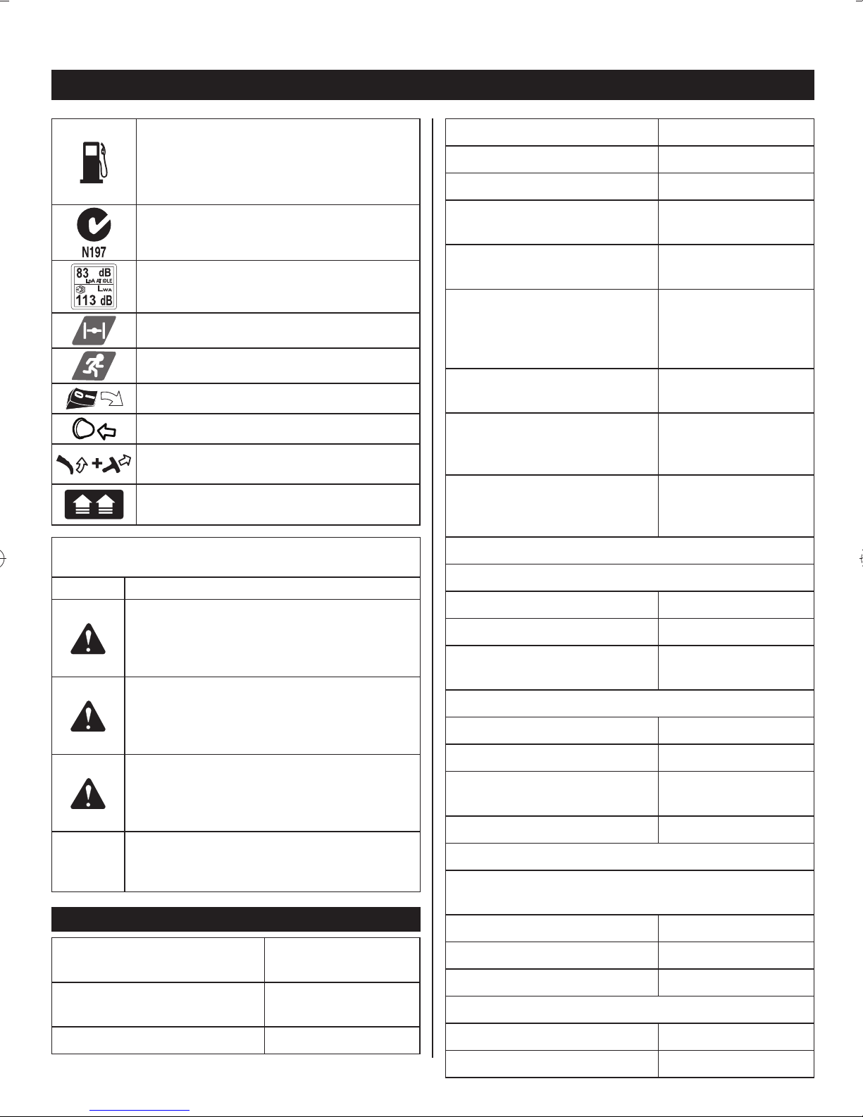
SYMBOLS
The following symbols are located on labels on the tool.
Please study them and learn their meaning. Proper
interpretation of these symbols will allow you to operate
the tool better and safer.
SYMBOL DESIGNATION/EXPLANATION
Indicates a potential personal injury
hazard.
Keep all bystanders at least 15 m away.
To reduce the risk of injury, user must read
and understand operator’s manual before
using this product.
Wear non-slip, heavy-duty gloves.
Wear non-slip safety footwear when using
this equipment.
Wear eye, hearing, and head protection
when operating this equipment.
The curved shaft is not suitable for use
with blade accessories.
Rotational direction and maximum speed
of the shaft for the cutting attachment.
GENERAL SAFETY WARNINGS
WARNING
Read and understand all instructions. Failure to
follow all instructions may result in serious personal
injury as well as damage to the product.
■Physical Condition of the Operator. Do not operate
this product when tired, ill or under the influence of
alcohol, drugs or medication.
■Clothing Requirements. Always wear long heavy
pants, boots and gloves. Do not wear loose clothing,
jewelry, short pants, sandals or go barefoot. Secure
hair so that it is above shoulder level to avoid
entanglement in moving parts.
■Protective Accessories Requirements. Wear eye
and hearing protection when operating this product.
Before use, inspect the condition of the trimmer.
Replace damaged parts. Check for fuel leaks.
Make sure all fasteners are in place and secure.
Replace cutting attachment parts that are cracked,
chipped or damaged in any way. Make sure the
cutting attachment is properly installed and securely
fastened. Be sure the cutting attachment shield is
properly attached and in the position recommended
by the manufacturer. Use only flexible, non-metallic
line recommended by the manufacturer. For example,
never use wire or wirerope, which can break off and
become a dangerous projectile.
■Proper Stance. Keep firm footing and balance. Do
not overreach. Keep the cutting attachment below
waist level. Keep all parts of your body away from the
rotating cutting attachment and hot surfaces.
■Exhaust Gases. Never start or run the product inside
a closed room or building; breathing exhaust fumes
can cause illness or death.
■Fueling. Mix and pour fuel outdoors where there are
no sparks and flames. Slowly remove the fuel cap only
after stopping the engine. Do not smoke while fueling
or mixing fuel. Wipe spilled fuel from the product.
Move at least 30ft. (9m) away from the fueling source
and site before starting the engine.
■Work Area. Clear the area to be cut before each use.
Remove all objects, such as rocks, broken glass,
nails, wire or string, that can be thrown or become
entangled in the cutting attachment. Clear the area
of children, bystanders and pets. At a minimum,
keep all children, bystanders and pets outside a 50
ft. (15 m) radius. Because there still may be a risk of
injury to bystanders from thrown objects, bystanders
should be encouraged to wear eye protection. If you
are approached while operating the product, stop the

3
English (Original Instructions)
Cutting swath 432 mm
Diameter of cutting line 2.4 mm and 2.7 mm
Engine displacement 25.4 cc
Maximum engine performance
(in accordance with ISO 8893) 0.9 kW
Maximum rotational frequency
of the spindle 12000 min-1
Engine speed (rotational
frequency) at recommended
max. spindle rotational
frequency
12000 min-1
Engine speed (rotational
frequency) at idle 2600-3200 min-1
Fuel consumption (in
accordance with ISO 8893) at
max. engine performance
0.54 kg/h
Specific fuel consumption (in
accordance with ISO 8893) at
max. engine performance
0.50 kg/h
Vibration (in accordance with ISO 22867)
Right handle
- Idle 14.9 m/s2
- Racing 3.7 m/s2
- Equivalent vibration total
value 9.3 m/s2
Left handle
- Idle 6.4 m/s2
- Racing 5.8 m/s2
- Equivalent vibration total
value 6.1 m/s2
Uncertainty 1.5 m/s2
Noise emission (in accordance with ISO 22868)
A-weight emission sound pressure level at the
operator's position
- Idle 76.8 dB(A)
- Racing 101.8 dB(A)
- Equivalent 98.8 dB(A)
A-weight emission sound power level
- Idle 84.8 dB(A)
- Racing 107.5 dB(A)
Use unleaded petrol intended for motor
vehicle use with an octane rating of 91 [(R
+ M)/2] or higher. This product is powered
by a 2-stroke engine and requires pre-
mixing petrol and 2-stroke lubricant.
C-Tick compliance mark. Product meets
applicable regulatory requirements.
Guaranteed sound pressure and sound
power lever.
Full choke position
Run choke position
Set switch to "ON"
Push primer bulb
Squeeze throttle and pull starter grip
Pull: Quick release tab
The following signal words and meanings are intended
to explain the levels of risk associated with this product.
Symbol Meaning
DANGER:
Indicates an imminently hazardous situation,
which, if not avoided, will result in death or
serious injury.
WARNING:
Indicates a potentially hazardous situation,
which, if not avoided, could result in death
or serious injury.
CAUTION:
Indicates a potentially hazardous situation,
which, if not avoided, may result in minor or
moderate injury.
CAUTION:
(Without Safety Alert Symbol) Indicates a
situation that may result in property damage.
SPECIFICATIONS
Weight without fuel and
trimmer head 5.00 Kg
Weight without fuel with
trimmer head 5.40 Kg
Fuel tank volume 620 cm3

4
English (Original Instructions)
37. 2cm Protruding line
FIGURE 9
20. Foam air filter
21. Air filter cover
22. Cover securing knob
FIGURE 10
23. Spark plug boot
24. Spark plug
FIGURE 11
25. Spark arrestor
ASSEMBLY
ATTACHING THE POWER HEAD TO THE TRIMMER
ATTACHMENT (FIG. 1)
■Follow these steps to connect the attachment to the
upper shaft (item 1).
■Loosen the knob (item 2) by turning it counter
clockwise.
■Align the button (item 3) on the attachment shaft with
the guide recess (item 4) on the upper shaft.
■Slide the attachment shaft into the upper shaft until the
attachment shaft clicks into place.
■Tighten the knob securely by turning it clockwise.
Removing the attachment from the upper shaft. Follow
these steps to remove the attachment from the upper
shaft.
■Loosen the knob by turning it counterclockwise.
■Push the button while pulling out the attachment.
ATTACHING THE FRONT HANDLE (FIG. 2)
■Remove the two securing bolts (item 9) from the front
handle (item 5).
■Position the front handle (item 5) onto the upper shaft
(item 1).
NOTE: The lever protruding from the front handle
should point to the left side of the trimmer (as shown
on Fig 1 & 2).
■Position the bracket (item 10) underneath the front
handle and secure in place by screwing the securing
bolts (item 9) through the base of the front handle into
to the bracket (item 10).
SAFETY GUARD (FIG. 3)
■Remove wing nut (item 14), flat washer (item 12), lock
washer (item 13) and bolt (item 11) from the Owner's
Kit.
■Place safety guard (item 6) over shaft and bracket.
■Install bolt through the slots in the tabs on safety guard
- Equivalent 107.5 dB(A)
Uncertainty 2.5 dB(A)
DESCRIPTION
FIGURE 1
1. Upper shaft
2. Knob
3. Button
4. Guide recess
5. Front handle
6. Safety guard
7. Trimmer line
8. ReelEasy™ trimmer head
FIGURE 2
5. Front handle
9. Securing bolts
10. Bracket
FIGURE 3
11. Securing bolt
12. Flat washer
13. Lock washer
14. Wing nut
FIGURE 4
15. On/Off switch
16. Throttle lock out button
17. Throttle trigger
18. Primer bulb
19. Starter grip
FIGURE 5
38. Choke lever
FIGURE 8
26. Bump head cover
27. Bump knob
28. Line spool
29. Bump head spring
30. Bump head securing bolt
31. Cutting head housing
FIGURE 8a
32. Drive shaft
33. Pro Cut II™ String head
34. Spool retainer
FIGURE 8b
35. Line exit holes
36. Line loading holes

5
English (Original Instructions)
and bracket on driveshaft housing.
■Install flat washer, lock washer and wing nut.
■Tighten securely.
INSTALLING THE REELEASY™ LINE TRIMMER HEAD
See Figures 8
■Stop the engine and disconnect the spark plug wire.
■Remove currently installed line trimmer head.
■Open the ReelEasy™ Line Trimmer Head by
depressing the latches on each side. The contents
of the line trimmer head are spring loaded, so keep
your other hand over the line trimmer head cover while
depressing the latches. (image 3)
■Remove the line trimmer head cover, bump knob, and
line spool and set aside.
■Place the cutting head housing on the drive shaft.
Make sure the housing is fully seated.
■Install the hex bolt to secure the line trimmer head
to the drive shaft. Tighten by using the hex-shaped
opening on the inside of the bump knob.
Note: Only use the bump knob to tighten the bolt. The
use of other tools may allow over tightening of the bolt,
which could damage the line trimmer head. (image 4)
■Reinstall the bump head spring into the line trimmer
head and push down to seat. (image 5)
■Reinstall the line spool. For the curved shaft attachment
with the ReelEasy™ cutting head the spool should be
placed so “This side out for curved shaft” is visible on
the line spool.
■Replace the bump knob by inserting it into the centre
of the line spool.
■Replace the line trimmer head cover, aligning latches
with openings in the line trimmer head. Press cover
and line trimmer head together until both latches snap
into openings securely.
■Install line as described in the next section of this
manual.
INSTALLING LINE IN REELEASY™ LINE TRIMMER
HEAD
See Figures 8
Use 2.4mm diameter monofilament line.
■Stop the engine and disconnect the spark plug wire.
■Cut one piece of line approximately 6.0 meters in
length.
■Rotate the bump knob on line trimmer head until line
on the centre of the bump knob aligns with arrows on
top of line trimmer head. (image 6)
■Insert one end of line into eyelet located on the side
of the line trimmer head and push until line comes out
through the eyelet on the other side. Continue to push
line through the line trimmer head until the middle
section of the line is inside the line trimmer head and
line outside the line trimmer head is evenly divided on
each side. (image 7-8)
■Rotate the knob on the line trimmer head to wind
the line. If using a curved shaft attachment, the knob
should be rotated counterclockwise.
■Wind the line until approximately 20cm remains
protruding from the line trimmer head.
■Replace the spark plug boot.
NOTE: For video instruction see the following website:
http://www.youtube.com/user/RYOBIAustralia
And watch the video;
RYOBI: How to install trimming line on a ReelEasy™ head
INSTALLING THE PRO CUT II™ HEAD TO THE LINE
TRIMMER HEAD
See Figures 8a
■Stop the engine and disconnect the spark plug wire.
■Remove the installed line head.
■Install the Pro Cut line trimmer head on the drive shaft
until fully seated.
■Install the spool retainer and turn clockwise
■Install cutting line as described in the next section in
this manual.
INSTALLING THE LINE IN THE PRO CUT II™ HEAD
See Figures 8b
■Use monofilament line diameter 2.7mm. Use original
manufacturers replacement line for best performance.
2.4mm Line is not compatible with the Pro Cut head.
For the head to secure the line safely 2.7mm line must
be used.
■Stop the engine and disconnect the spark plug wire.
■Remove old line by pulling it from the holes located on
the top of the line head.
■Gather two of the pre-cut lengths of trimmer line
provided or cut two pieces of trimmer line (in 28cm
lengths).
■Insert the line into the load slots located on the sides
of the line head. Line should be pushed in until
approximately 2cm protrudes from the holes on the
top of the line head.
NOTE: For video instruction see the following website:
http://www.youtube.com/user/RYOBIAustralia
And watch the video;
RYOBI: How to install trimming line on a Pro-Cut II™ head

6
English (Original Instructions)
OPERATION
FUEL AND REFUELING
Handling the fuel safely
Always handle fuel with care, it is highly flammable.
■Always refuel outdoors where there are no sparks and
flames. Do not inhale fuel vapors.
■Do not let petrol or oil come in contact with your skin.
■Keep petrol and oil away from the eyes. If petrol
or oil comes in contact with the eyes, wash them
immediately with clean water. If irritation is still present,
see a doctor immediately.
■Clean up spilled petrol immediately.
MIXING THE FUEL
■This product is powered by a 2-stroke engine and
requires pre-mixing petrol and 2-stroke oil. Pre-mix
unleaded petrol and 2-stroke engine oil in a clean
container approved for petrol.
IMPORTANT! Failure to use two stroke oil will result in the
engine seizing. Such damage will not be covered under
warranty.
■This engine is certified to operate on unleaded petrol
intended for automotive use with an octane rating of
91 ([R + M] / 2) or higher.
■Do not use any type of pre-mixed petrol / oil from fuel
service stations, this includes the pre-mixed petrol / oil
intended for use in mopeds, motorcycles, etc.
■Use synthetic 2-stroke oil only. Do not use automotive
oil or 2-stroke outboard oil.
■Mix 2% synthetic 2-stroke oil into the petrol. This is a
50:1 ratio.
■Mix the fuel thoroughly and also each time before
fueling.
■Mix in small quantities. Do not mix quantities larger
than usable in a 30 day period. Synthetic 2-stroke oil
containing a fuel stabilizer is recommended.
FILLING THE TANK
■Clean surface around fuel cap to prevent
contamination.
■Loosen fuel cap slowly to release pressure and to
keep fuel from escaping around the cap.
■Carefully pour fuel mixture into the tank. Avoid spillage.
■Prior to replacing the fuel cap, clean and inspect the
gasket.
■Immediately replace fuel cap and hand tighten. Wipe
up any fuel spillage. Move 9 m away from refueling site
before starting engine.
Note: It is normal for smoke to be emitted from a new
engine during and after first use.
WARNING
Always shut off engine before fueling. Never add fuel to
a machine with a running or hot engine. Move at least
9m from refueling site before starting engine. Do not
smoke!
50:1 Petrol to Oil Mixing Chart
1 litre + 20 ml =
2 litres + 40 ml =
3 litres + 60 ml = 50: 1 (2%)
4 litres + 80 ml =
5 litres + 100 ml =
WARNING
The product may throw objects during operation,
causing injury to the operator or to bystanders. Always
wear suitable eye protection, long heavy pants and
boots while operating the product.
STARTING THE PRODUCT (FIG. 4-5)
Starting the product differs depending on whether the
engine is cold or warm. Refer to the label on the air filter
cover.
To start a cold engine
Follow these steps to start a cold engine:
1. Lay the product on a flat, bare surface.
2. Ensure the engine switch is in the I (ON) position (item
15).
3. Push the primer bulb approximately 10 times (item 18).
4. Set the choke lever (item 38) to Full position .
5. Hold down the throttle lock-off button (item 16) and
squeeze the throttle trigger (item 17).
6. Pull the starter grip (item 19) with a quick firm and
consistent upward motion until the engine attempts to
start (No more than 4 pulls).
7. Set the choke lever (item 38) to the RUN position
8. Hold down the throttle the lock-off button (item 16) and
squeeze the throttle trigger (item 17).
9. Pull the starter grip (item 19) with a quick firm and
consistent upward motion until the engine starts (No
more than 6 pulls).

7
English (Original Instructions)
NOTE: If engine does not start, return to step 4 and repeat
the steps.
NOTE: When the engine starts, let it run for 30 seconds
prior to operation.
To start a warm engine
Follow these steps to start a warm engine:
1. Lay the product on a flat, bare surface.
2. Ensure the engine switch is in the I (ON) position (item
15).
3. Ensure the choke lever (item 38) is set to the Run
position .
4. Hold down the throttle lock-off button (item 16) and
squeeze the throttle trigger (item 17).
5. Pull the starter grip (item 19) with a quick firm and
consistent upward motion until the engine starts (No
more than 6 pulls).
NOTE: If engine does not start, return to step 4 on the "To
start a cold engine" and repeat the steps.
STOPPING THE PRODUCT
■Release the throttle trigger.
■Push the engine switch (item 15) to the O (OFF)
position.
OPERATION
It has been reported that vibrations from hand-held tools
may contribute to a condition called Raynaud’s Syndrome
in certain individuals. Symptoms may include tingling,
numbness and blanching of the Fingers, usually apparent
upon exposure to cold.
Hereditary factors, exposure to cold and dampness, diet,
smoking and work practices are all thought to contribute to
the development of these symptoms. There are measures
that can be taken by the operator to possibly reduce the
effects of vibration:
a. Keep your body warm in cold weather. When operating
the unit wear gloves to keep the hands and wrists
warm. It is reported that cold weather is a major factor
contributing to Raynaud’s Syndrome.
b. After each period of operation, exercise to increase
blood circulation.
c. Take frequent work breaks. Limit the amount of
exposure per day.
d. Injuries may be caused, or aggravated by prolonged
use of a tool. When using any tool for prolonged
periods, ensure you take regular breaks.
If you experience any of the symptoms of this condition,
immediately discontinue use and see your doctor about
these symptoms.
OPERATING THE TRIMMER (FIG. 6)
Follow these steps to operate the curved shaft trimmer.
■Start the trimmer.
■Hold the trimmer at waist level with your right hand
on the trigger handle and your left hand on the front
handle.
■Place the product on the right side of your body with
the engine behind and away from your body.
■Trim grass and weeds in a left-to-right motion with the
line parallel to the ground.
TO ADVANCE THE CUTTING LINE ON THE
REELEASY™ TRIMMER HEAD
Follow these steps to advance the cutting line.
■Start the trimmer.
■Tap the bump knob lightly on the ground while the
motor is running. The line will only advance with the
engine at full throttle. Do not hold the bump knob on
the ground.
■Do not bump the knob on hard surfaces such as
concrete. This may cause damage to the bump knob.
Note: The blade on the safety guard will cut the line to the
proper length.
Note: To help prevent line tangle, tap only once to
lengthen the line. If additional line is required, wait a few
seconds before retapping the bump knob. Do not allow the
line to wear too short. Keep the cutting line at full length.
MAINTENANCE
MAINTENANCE
WARNING
When servicing, use only identical replacement parts.
Use of any other parts may create a hazard or cause
product damage.
WARNING
Always wear safety goggles or safety glasses with side
shields during tool operation. If operation is dusty, also
wear a dust mask.
WARNING
Before inspecting, cleaning, or servicing the machine,
shut off engine, wait for all moving parts to stop, and
disconnect spark plug lead and move it away from
spark plug. Failure to follow these instructions can
result in serious personal injury or property damage.

8
English (Original Instructions)
WARNING
Neglected or poorly conducted maintenance may
create additional hazards. Do not attempt to repair or
maintain this product if you are not qualified to do so.
If in doubt, return to a service centre for professional
assistance.
GENERAL MAINTENANCE
Avoid using solvents when cleaning plastic parts. Most
plastics are susceptible to damage from various types of
commercial solvents and may be damaged by their use.
Use clean cloths to remove dirt, dust, lubricant, grease.
WARNING
Do not at any time let brake fluids, petrol, petroleum-
based products, penetrating lubricants, etc., come
in contact with plastic parts. Chemicals can damage,
weaken or destroy plastic which may result in serious
personal injury.
You can often make adjustments and repairs described in
this manual. For other repairs, have the trimmer serviced
by a service dealer.
CLEANING THE AIR FILTER (FIG. 9)
A dirty air filter will cause starting difficulty, loss of
performance, and shorten the life span of the engine.
Check the air filter monthly. For best performance, replace
the air filter at least once a year.
■Loosen the air filter cover (item 21) by turning the knob
(item 22) counterclockwise.
■Remove the air filter (item 20).
■Clean the foam filter element with warm soapy water.
Rinse and let dry.
NOTE: If the foam filter element is damaged, it should be
replaced.
■Apply a light coat of engine oil to the foam filter
element, then squeeze it out.
■Reinstall the air filter.
NOTE: Make sure the filter is seated properly inside the
cover. Installing the filter incorrectly will allow dirt to enter
the engine, causing rapid engine wear.
■Reinstall the cover and tighten knob to secure.
WARNING
Make sure the trimmer head stops rotating when you
release the trigger. Contact with a rotating trimmer head
could cause personal injury.
CHECKING THE FUEL CAP
WARNING
A leaking fuel cap is a fire hazard and must be replaced
immediately.
The fuel cap contains a non-serviceable filter and
check valve. A clogged fuel filter causes poor engine
performance. If performance improves when the fuel cap
is loosened, the check valve may be faulty or the filter may
be clogged. Replace the fuel cap if necessary.
REPLACING THE SPARK PLUG (FIG. 10)
This engine uses a Champion RCJ6Y or NGK BPMR7A
spark plug. Use an exact replacement and replace
annually.
Follow these steps to replace the spark plug.
■Remove the spark plug boot (item 23).
■Loosen the spark plug (item 24) by turning it
counterclock wise with a 16mm socket.
■Remove the spark plug.
■Hand thread the new spark plug, turning it clockwise.
■Tighten with a socket. Do not overtighten.
CAUTION
Be careful not to cross-thread the spark plug. Cross-
threading will seriously damage the engine.
CLEANING THE SPARK ARRESTOR (FIG. 11)
Follow these steps to clean the spark arrestor.
■Locate the spark arrestor (item 25) through the hole on
the muffler exit hole.
■Remove the spark arrestor using needle-nosed pliers.
■Clean the spark arrestor with a small wire brush.
■Replace the spark arrester.
STORING THE PRODUCT
Storing the product differs depending on the amount of
time it will be in storage.
Follow these steps for short term product storage.
■Clean all foreign material from the product.
■Store the product in a well-ventilated place that is
inaccessible to children.
If you do not intend to use the product for more than one
month, follow the storage procedures below.
■Drain all fuel from the tank into a container approved
for petrol.

9
English (Original Instructions)
■Run the engine until it stops.
■Clean all foreign material from the product.
■Store the product in a well-ventilated place that is
inaccessible to children.
Note: Keep the product away from corrosive agents
such as garden chemicals.
Important: Abide by all local and government
regulations for the safe storage and handling of petrol.

10
English (Original Instructions)
TROUBLE SHOOTING
PROBLEM POSSIBLE CAUSE SOLUTION
Engine will not start.
1. Switch set to the O (OFF) position. 1. Set switch to the I (ON) position.
2. No spark.
2. Remove the spark plug. Reattach the spark plug cap
and lay the spark plug on the metal cylinder. Pull
the starter cord and watch for a spark at the spark
plug tip. If there is no spark, repeat the test with a
new spark plug.
3. No fuel. 3. Push primer bulb until the bulb is full of fuel. If the
bulb does not fill, the primary fuel delivery system
is blocked. If the primer bulb fills, the engine may
be flooded. (See next item.)
4. Flooded engine.
4. Turn the on/off switch to the “O” (off) position and
completely remove the spark plug from both the
engine and the spark plug boot. Turn the product
so that the spark plug hole is aimed at the ground.
Make sure the choke lever is set to and pull
the starter cord 10 to 14 times. This clears excess
fuel from the engine. Clean and reinstall the spark
plug. With the throttle trigger fully depressed, pull
the starter cord 3 times. If the engine does not
start, set the choke lever to and follow normal
starting instructions. If the engine still fails to start,
repeat the procedure with a new spark plug.
5. Starter cord is hard to pull.
5. Contact a service dealer.
Engine does not reach full speed
and emits excessive smoke.
1. Check oil fuel mixture. 1. Use fresh fuel and the correct 2-stroke oil mix.
2. Air filter is dirty. 2. Clean the air filter according to the instructions in
the Maintenance section.
3. Spark arrestor screen is dirty. 3. Contact a service dealer.
Cutting line will not advance when
using bump feed action.
1. Line welded to itself. 1. Lubricate with silicone spray.
2. Not enough line on the spool. 2. Install more line.
3. Line worn too short. 3. Pull line while alternately pressing down on and
releasing the retaining cap.
4. Line tangled on spool. 4. Remove line from spool and rewind.
5. Engine speed too slow. 5. Advance line at full throttle.
6. Line spool installed back to front.
6. Ensure the writing on the line spool is facing the
correct way; THIS SIDE OUT FOR CURVED
SHAFT.
Grass wraps around the trimmer
head assembly and the attachment
shaft.
1. Cutting tall grass at ground level. 1. Cut tall grass from the top down.
2. Operating the product at part
throttle. 2. Operate the product at full throttle.
Oil drips from muffler.
1. Operating the product at part
throttle. 1. Operate the product at full throttle.
2. Check oil/fuel mixture. 2. Use fresh fuel and the correct 2-stroke oil mix.
3. Air filter is dirty. 3. Clean the air filter according to the instructions in
the Maintenance section.

Techtronic Industries (Australia) Pty. Ltd.
Level 1, 660 Doncaster Road
Doncaster, VIC 3108, Australia
Techtronic Industries New Zealand Ltd.
18-26 Amelia Earhart Avenue
Mangere, Auckland 2022, New Zealand
960710006-01
20130801v1
Table of contents
Other Ryobi Trimmer manuals

Ryobi
Ryobi RY40603 User manual

Ryobi
Ryobi P20018 User manual

Ryobi
Ryobi RLT-710 Operation manual

Ryobi
Ryobi OLT1832 User manual

Ryobi
Ryobi C430 RY34421 User manual

Ryobi
Ryobi RLT254CSEON User manual

Ryobi
Ryobi RLT-552 Operation manual

Ryobi
Ryobi OHT1850S User manual

Ryobi
Ryobi P601 User manual

Ryobi
Ryobi RBC52FSB User manual

Ryobi
Ryobi 725rE User manual

Ryobi
Ryobi RHT6760RL User manual

Ryobi
Ryobi PLT3043S User manual

Ryobi
Ryobi RBC42FSBO User manual

Ryobi
Ryobi RY26000 User manual

Ryobi
Ryobi RY28120 User manual

Ryobi
Ryobi RGT2500 Operation manual

Ryobi
Ryobi RY24200 User manual

Ryobi
Ryobi 875r User manual

Ryobi
Ryobi OLT1825 User manual