S.A. Sistel YAV90057 User manual

160-Channels, 2A Mux./Matrix
YAV90057
YAV90057CM00E03
Created 12/02/13
Updated 12/02/13

TECHNICAL MANUAL 620057E03
Due to the continuous products improvement, the indications of the present manual can be modified without previous warning and in any case are a
contract commitment. The present information publishing does not represent resignation of intellectual property or patent.
Copyright ©2009-2010 S.A. Sistel -E 08211 BARCELONA Pag. 2
This manual is related to the following product:
Product –P/N
YAV90057
Version
01.01
Document History
Version
Issued date
Reason
E01
02/2013
First Release
E02
11/2015
CE Revision // Remove Packaging Chapter
E03
07/2021
Added section
Hardware History
Version
Issued date
Reason
01
02/2013
First Release
Software History
Version
Issued date
Reason
01
02/2013
First Release
All S.A. Sistel’s hardware and software products are covered by na-
tional and international patents and/or copyright or with pending trade
marks or patents. Any violation of the intellectual copyrights willbe pros-
ecuted with all legal means available.
S.A. Sistel Solsonès, 87-89 E-08211 BARCELONA

TECHNICAL MANUAL 620057E03
Due to the continuous products improvement, the indications of the present manual can be modified without previous warning and in any case are a
contract commitment. The present information publishing does not represent resignation of intellectual property or patent.
Copyright ©2009-2010 S.A. Sistel -E 08211 BARCELONA Pag. 3
0. Before you begin ............................................................................................................5
1. Safety...............................................................................................................................5
1.1 Precautions against damage to people......................................................................5
1.2 Precautions against damage to the product ..............................................................6
1.3 Limits of the guarantee..............................................................................................6
2. Certifications...................................................................................................................7
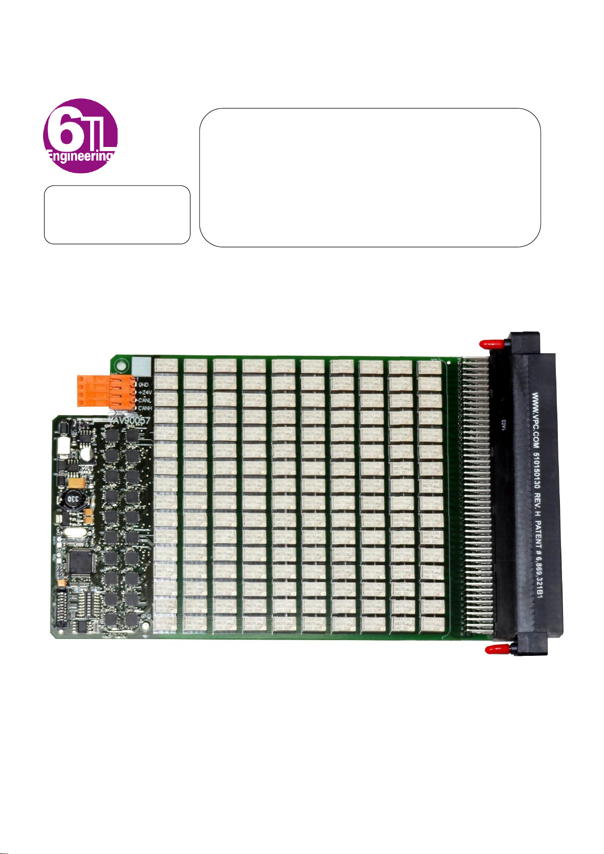
3. Description and main features ......................................................................................8
3.1General features........................................................................................................8
3.2 Applications ...............................................................................................................8
3.3 Ordering information..................................................................................................8
3.4 Device electrical Characteristics................................................................................9
3.5 Electric Diagram ........................................................................................................9
3.5.1 Connector X2.................................................................................................... 10
4. YAV modules common information............................................................................11
4.1 SW1 DIP switch functionality...................................................................................11
4.1.1 CAN bus communication speed. ...................................................................... 11
4.1.2 YAV module address........................................................................................ 11
4.2 YAV modules standard addressing & Virginia Panel Receivers ..............................12
4.1 Jumpers behavior....................................................................................................14
4.2 YAV boards Dimensions..........................................................................................15
5. Low level CAN commands...........................................................................................16
5.1 Example: Managing a YAV board using C language...............................................16
6. PHI6-Explorer panel......................................................................................................19
7. Install/Uninstall YAV boards into/from a VPC Receiver ............................................21
7.1 Modules in receiver side..........................................................................................21
7.1.1 Interfaces w/Quadrapaddle............................................................................... 22
7.2Connections.............................................................................................................23
7.2.1 Connecting cables into YAV board terminals.................................................... 23
8. Getting started with your YAV board..........................................................................24
8.1 NI CAN board ..........................................................................................................24
8.2 CAN bus wiring........................................................................................................24
8.3 PHI6-EXPLORER....................................................................................................24
9. YAV boards overview...................................................................................................25
10. Operation.......................................................................................................................25
10.1 Outputs Activation....................................................................................................25
10.2 Soft Panel................................................................................................................25
TABLE OF CONTENTS

TECHNICAL MANUAL 620057E03
Due to the continuous products improvement, the indications of the present manual can be modified without previous warning and in any case are a
contract commitment. The present information publishing does not represent resignation of intellectual property or patent.
Copyright ©2009-2010 S.A. Sistel -E 08211 BARCELONA Pag. 4
11. Test ................................................................................................................................27
11.1 Test Report model...................................................................................................28
12. F.A.Q.s...........................................................................................................................29

TECHNICAL MANUAL 620057E03
Due to the continuous products improvement, the indications of the present manual can be modified without previous warning and in any case are a
contract commitment. The present information publishing does not represent resignation of intellectual property or patent.
Copyright ©2009-2010 S.A. Sistel -E 08211 BARCELONA Pag. 5
0.Before you begin
Thank you very much for purchasing this system/module.
This manual contains the information of the characteristics, performance and usage of the system/module required for
using it.
When using the system, observe the following:
- Read this manual carefully to understand the contents well, and make the proper use of this system accordingly.
- Keep the manual safely for ready reference at any time. For basic operation of the system/module,alse read the
relevant manuals carefully to understand the contents well, and then make the proper use of this system ac-
cordingly.
1.Safety
Follow the following safety measures to avoid and prevent damaging this product, products connected to it, or people.
Only qualified and entitled
1
personnel are authorized to carry out operations of installation and routine on the devices
described in this manual. The company installing it would bear responsibility for any security or operating failure of the
lift, when such failure is due to the parameters incorrect programming.
The product described in this manual can be configured to comply with the ruling of different countries. The manufacturer
does not hold any responsibility if the company installing it does not configured it according to the legal, commercial or
security prescriptions that may be in force in the place of installation or otherwise agreed with the customer.
Should you need to access other components of the system while you are using this product, as a measure of precaution,
read the General Safety Summary in the other products manual.
1.1 Precautions against damage to people
Do not work on the product with the
power on.
To avoid electrical discharge, this product must not be handled with
the system powered on and in any case can operate without the pro-
tective covers.
The device has mobile parts that can be
in motion by operating electric or elec-
tronic control units.
Before starting any operation, make sure that there are no people who
could be affected by any moving part.
Check through-out each one of the secu-
rity devices before the unit comes into op-
eration.
Each one of the safety switches must be individually checked and,
under no circumstances, the device must remain on service without
ensuring the correct operation of the security devices.
1
The qualified staff must have proved their technical knowledge of this product and should have the corresponding accreditation.

TECHNICAL MANUAL 620057E03
Due to the continuous products improvement, the indications of the present manual can be modified without previous warning and in any case are a
contract commitment. The present information publishing does not represent resignation of intellectual property or patent.
Copyright ©2009-2010 S.A. Sistel -E 08211 BARCELONA Pag. 6
1.2 Precautions against damage to the product
Do not insert / unplug cards or other elec-
tronic elements when powered up
The connection/disconnection of the I/O’s when plugged to the power
could produce a sequence of connections that could damage elec-
tronic components which had been previously connected to their cor-
responding reference earth.
Do not use insulation testers.
The insulation testers work at very high voltages, and are capable of
destroying the semiconductors. Under no circumstances should the
“Megger” type of testers be used between electronic systems.
Do not force the connection tag strips
The connection tag strips are connected exerting a small pressure. If
you encounter difficulty to plug them this may mean that they are up-
side down or not aligned. If they are forced, besides the damage to
the strip you can cause damages on the electronics.
Secure the ground connections quality.
All the ground connections must be star-type and with the suitable
section. Loop ground connections are potential receptor antennas
with capacity to generate important current peaks.
Use suitable packing material for trans-
portation
An electronic module with a lot of fragile components should be trans-
ported with a good protection packaging. A collision can cause dam-
ages that could appear long time after the start up.
Do not install this product near heat
sources, strong vibrations or high humid-
ity that exceeds the technical specifica-
tions.
Check that the product works without vibrations that exceed the max-
imum levels specified, and which could damage its integrity or cause
a contact to become disconnected. The product should work without
humidity and in the temperature range detailed in the technical spec-
ifications.
1.3 Limits of the guarantee
1. Products are supplied to the latest available development state at the time of manufacture. Should there be any
future changes for functional or productive improvements of the products; the manufacturer does not hold any
obligation to reprocess at no charge the products that have been already manufactured to upgrade them to the
latest versions.
2. All the products supplied by S.A. Sistel have passed all established quality controls as well as the EMC (Elec-
tromagnetic Compatibility Checks). The manufacturer cannot be held responsible for any damage produced by
defective manipulation, installation or incompatibility with other products.
3. The products’ guarantee will only be in force when the installation has been done in accordance with the tech-
nical prescriptions in this manual and the settled general standards: Low Voltage Electro Technical Regulation
(or equivalent for each country) and CE regulations for the Electromagnetic Compatibility.
4. The commutation of highly unsettling loads nearby (Frequency converters, doors operators, coils, fluorescent
lamps, contactors, etc.), require the installation of the corresponding interference suppression/reduction re-
sources and connections to earth are required
2
. If these requirements are not followed or are defectively installed
there may be severe failures in the electronic devices, for which the installing company will be held responsible.
5. All equipment under guarantee that be sent for repair must have the manufacturing label with its serial number
6. The guarantee period is years since invoicing date.
7. Device operation under thermal or voltage conditions out of technical specifications detailed in this operation
manual cancels guarantee terms.
2
RF filters on the input and output frequency converters, RC net, diodes and/or varistors in the coils, screened cables in the VVVF
motors, screened starters, etc.

TECHNICAL MANUAL 620057E03
Due to the continuous products improvement, the indications of the present manual can be modified without previous warning and in any case are a
contract commitment. The present information publishing does not represent resignation of intellectual property or patent.
Copyright ©2009-2010 S.A. Sistel -E 08211 BARCELONA Pag. 7
2.Certifications
Declaration of Conformity
S.A. Sistel declare, under his sole responsibility, that the product
YAV90057–160-Channel, 2A Relay Multi-configuration Multiplexer
to which this declaration relates, meets the provisions of the EU Directives listed below:
•Electro Magnetic Compatibility (EMC) directive, 2004/108/CE refereeing to
•Low voltage directive, 2006/95/CE
and therefore, the CE mark showed below is applied.
For accessories or other elements that can be connected to this product, see their corre-
sponding Declaration of Conformities
The conformity mark is given by the CE mark and the year when it was applied
Authorized by:
Representative: Jordi Batet
Title: General Manager
Company: SA Sistel - Barcelona
Barcelona, July 15th 2012
98

TECHNICAL MANUAL 620057E03
Due to the continuous products improvement, the indications of the present manual can be modified without previous warning and in any case are a
contract commitment. The present information publishing does not represent resignation of intellectual property or patent.
Copyright ©2009-2010 S.A. Sistel -E 08211 BARCELONA Pag. 8
3.Description and main features
The YAV module contents 160 SPST Relays, structured in 10 multiplexer branches of 16 relays.
The branch commons are accessible from three connector pins in order to make easy the configu-
rations in different multiplexer modes.
3.1 General features
•160-Channels 2A SPST Relays
•500 V Isolation between banks
•CAN bus
•High density integration: Only 15 mm width
•LabView drivers available
3.2 Applications
•Switching unit in ATE systems in single pole or multi-pole joining banks
3.3 Ordering information
Descripción
P/N
160-Channel, 2A Relay Multiconfiguration Multiplexer
Scope of supply:
•Module P/N YAV90057
•4 Pole 3,5 mm pitch Weidmüller connector (CAN and Power supply)
YAV90057

TECHNICAL MANUAL 620057E03
Due to the continuous products improvement, the indications of the present manual can be modified without previous warning and in any case are a
contract commitment. The present information publishing does not represent resignation of intellectual property or patent.
Copyright ©2009-2010 S.A. Sistel -E 08211 BARCELONA Pag. 9
3.4 Device electrical Characteristics
Parameter
At Te= 5 … 65ºC, unless otherwise specified
Symbol
Values
Unit
Min.
Typ.
Max.
Module Operating Parameters
Control Voltage
Vcc
18
24
32
VDC
Operating current @24VDC and 160 relays ON
ID
-
-
1.300
mA
Contacts Data
Maximum switching voltage
VMax
-
-
220
250
VDC
VAC
Rated current
IR
-
2
-
A
Limit continuous current
IC
-
-
2
A
Switching power
Ps
-
-
60
62.5
W
VA
Minimum switching voltage
Vmin
100
-
-
mV
Operate time
ton
1
-
3
ms
Release time
toff
3
-
5
ms
Bounce time
tbnc
-
1
5
ms
Initial contact resistance
<50mΩat 10 mA/20 mV
Thermoelectric potencial
<10mV
3.5 Electric Diagram

TECHNICAL MANUAL 620057E03
Due to the continuous products improvement, the indications of the present manual can be modified without previous warning and in any case are a
contract commitment. The present information publishing does not represent resignation of intellectual property or patent.
Copyright ©2009-2010 S.A. Sistel -E 08211 BARCELONA Pag. 10
3.5.1 Connector X2
A
Description
B
Description
C
Description
D
Description
1
K001
1
K017
1
K033
1
2
K049
2
K065
2
K081
2
Common 01
3
K097
3
K113
3
K129
3
K145
4
K002
4
K018
4
K034
4
Common 02
5
K050
5
K066
5
K082
5
Common 03
6
K098
6
K114
6
K130
6
K146
7
K003
7
K019
7
K035
7
Common 04
8
K051
8
K067
8
K083
8
Common 05
9
K099
9
K115
9
K131
9
K147
10
K004
10
K020
10
K036
10
Common 01
11
K052
11
K068
11
K084
11
Common 01
12
K100
12
K116
12
K132
12
K148
13
K005
13
K021
13
K037
13
Common 02
14
K053
14
K069
14
K085
14
Common 02
15
K101
15
K117
15
K133
15
K149
16
K006
16
K022
16
K038
16
Common 03
17
K054
17
K070
17
K086
17
Common 03
18
K102
18
K118
18
K134
18
K150
19
K007
19
K023
19
K039
19
Common 04
20
K055
20
K071
20
K087
20
Common 04
21
K103
21
K119
21
K135
21
K151
22
K008
22
K024
22
K040
22
Common 05
23
K056
23
K072
23
K088
23
Common 05
24
K104
24
K120
24
K136
24
K152
25
K009
25
K025
25
K041
25
Common 06
26
K057
26
K073
26
K089
26
Common 06
27
K105
27
K121
27
K137
27
K153
28
K010
28
K026
28
K042
28
Common 07
29
K058
29
K074
29
K090
29
Common 07
30
K106
30
K122
30
K138
30
K154
31
K011
31
K027
31
K043
31
Common 08
32
K059
32
K075
32
K091
32
Common 08
33
K107
33
K123
33
K139
33
K155
34
K012
34
K028
34
K044
34
Common 09
35
K060
35
K076
35
K092
35
Common 09
36
K108
36
K124
36
K140
36
K156
37
K013
37
K029
37
K045
37
Common 10
38
K061
38
K077
38
K093
38
Common 10
39
K109
39
K125
39
K141
39
K157
40
K014
40
K030
40
K046
40
Common 06
41
K062
41
K078
41
K094
41
Common 07
42
K110
42
K126
42
K142
42
K158
43
K015
43
K031
43
K047
43
Common 08
44
K063
44
K079
44
K095
44
Common 09
45
K111
45
K127
45
K143
45
K159
46
K016
46
K032
46
K048
46
Common 10
47
K064
47
K080
47
K096
47
48
K112
48
K128
48
K144
48
K160

TECHNICAL MANUAL 620057E03
Due to the continuous products improvement, the indications of the present manual can be modified without previous warning and in any case are a
contract commitment. The present information publishing does not represent resignation of intellectual property or patent.
Copyright ©2009-2010 S.A. Sistel -E 08211 BARCELONA Pag. 11
4.YAV modules common information
4.1 SW1 DIP switch functionality
The eight switches contained in SW1 are covering the following functionalities:
•Set CAN bus speed
•Set module address
ON
1 2 3 4 5 6 7 8
ON=1
OFF=0
4.1.1 CAN bus communication speed.
Switches 1 and 2 set the CAN communication speed:
Select 50Kb/s to communicate with Phi6 and all 6TL modules. All devices communicating through
the CAN network must have the same speed configured in order to communicate properly.
ON
1 2 3 4 5 6 7 8
ON=1
OFF=0
00 = 50 kB/s
01 = 125 kB/s
10 = 100 kB/s
11 = 250 kB/s
4.1.2 YAV module address
The logic address is composed by 2 elements: the module identification and the hardware address.
The hardware address is selected by switches 3 to 8 of SW1, being 3 the least significant bit (LSB).
The module identification is contained in the module firmware and cannot be changed. There is a
different identification for each YAV module type. Therefore, modules of different module identifica-
tion can have the same hardware address.

TECHNICAL MANUAL 620057E03
Due to the continuous products improvement, the indications of the present manual can be modified without previous warning and in any case are a
contract commitment. The present information publishing does not represent resignation of intellectual property or patent.
Copyright ©2009-2010 S.A. Sistel -E 08211 BARCELONA Pag. 12
Since there are 6 bits there are up to 64 possible addresses (from 0 to 63).
ON
1 2 3 4 5 6 7 8
ON=1
OFF=0
LSB MSB
Board Address
4.2 YAV modules standard addressing & Virginia Panel Receivers
Although the user can set any address for his modules, 6TL defines standard addressing for the
modules that are installed by default in 6TL testing platforms.
The motivation is to ease compatibility between platforms and systems and 6TL strongly recom-
mends following this standard in order to facilitate platforms setup and maintenance.
The following table shows the standard addressing for the YAV modules and 6TL products installed
in the different slots of the Virginia Panel receivers:
SW1 Address
(Binary code)
Phi6 Ad-
dress
Skeeter
S6
Gemini
10
Gemini
12
Gemini
12X
Gemini
25
MSB
LSB
00 0001
1
A1
1
A1
A1
1
00 0010
2
A2
2
A2
A2
2
00 0011
3
B1
3
A3
A3
3
00 0100
4
B2
4
A4
A4
4
00 0101
5
C1
5
B1
B1
5
00 0110
6
C2
6
B2
B2
6
00 0111
7
7
B3
B3
7
00 1000
8
8
B4
B4
8
00 1001
9
9
C1
C1
9
00 1010
10
10
C2
C2
10
00 1011
11
C3
C3
11
00 1100
12
C4
C4
12
00 1101
13
A5
13
00 1110
14
A6
14
00 1111
15
B5
15
01 0000
16
B6
16
01 0001
17
C5
17
01 0010
18
C6
18
01 0011
19
19
01 0100
20
20
01 0101
21
21
01 0110
22
22
01 0111
23
23
01 1000
24
24
01 1001
25
25

TECHNICAL MANUAL 620057E03
Due to the continuous products improvement, the indications of the present manual can be modified without previous warning and in any case are a
contract commitment. The present information publishing does not represent resignation of intellectual property or patent.
Copyright ©2009-2010 S.A. Sistel -E 08211 BARCELONA Pag. 13
Next table shows the list of YAV modules that are installed in each of the 6TL platforms. Note that
the “Platform” column indicates whether the module is actually installed in the platform or not:
First (YAV Module Identification) and second (Phi6 Address) columns are composing the address
of the module when it is part of a 6TL testing platform.
Fourth column (YAV module) refers to 6TL’s internal code for the PCB HW used by the module.
Fifth column (Firmware name) is referring to 6TL’s internal name given to the firmware running in
the PCB HW of the module.
Sixth column (Function; Module Alias) refers to the default (and standard 6TL) name given by Phi6
to each module, depending on his function in the 6TL platform. These aliases could be changed
through Phi6 Explorer, edit Tags.
Seventh column (Platform) is informing about what platform uses what modules. A cross [X] is indi-
cating that the module is always installed as standard delivery. A cross with bar [-/X] is indicating
that that module is a potential option for that platform.
Eighth column (Module P/N) is showing the module commercial P/N of the module (Typically 8 or 9
digit number. If less numbers in the table, complete with 0’s).

TECHNICAL MANUAL 620057E03
Due to the continuous products improvement, the indications of the present manual can be modified without previous warning and in any case are a
contract commitment. The present information publishing does not represent resignation of intellectual property or patent.
Copyright ©2009-2010 S.A. Sistel -E 08211 BARCELONA Pag. 14
4.1 Jumpers behavior
Description
Definition of Behavior
BOOT0
Factory use. Must be OPEN on operation.
RESET
Must be OPEN on operation. Temporary bridge here, causes a reset of the
board.
CAN-END
Closing jumper place 120 Ohm resistor between CAN-High and CAN-Low
signals of CAN-Bus.

TECHNICAL MANUAL 620057E03
Due to the continuous products improvement, the indications of the present manual can be modified without previous warning and in any case are a
contract commitment. The present information publishing does not represent resignation of intellectual property or patent.
Copyright ©2009-2010 S.A. Sistel -E 08211 BARCELONA Pag. 15
4.2 YAV boards Dimensions
YAV90057 is Form L

TECHNICAL MANUAL 620057E03
Due to the continuous products improvement, the indications of the present manual can be modified without previous warning and in any case are a
contract commitment. The present information publishing does not represent resignation of intellectual property or patent.
Copyright ©2009-2010 S.A. Sistel -E 08211 BARCELONA Pag. 16
5.Low level CAN commands
Following, details on all CAN messages available to manage the YAV90057 module
5.1 Example: Managing a YAV board using C language
Following example is showing how to manage a YAV board by using NI-CAN interface and C lan-
guage.
We strongly recommend the software engineer to read NI-CAN manual for clear understanding on
how to implement the communication with YAV boards (http://www.ni.com/pdf/manu-
als/370289k.pdf)
The YAV board used for this example is YAV904X8.
/************************************************************
Example showing how to command the YAV904X8 board from a PC,
using a National Instruments NICAN interface board.
To be compiled with MS Visual C as a console application.
************************************************************/
#include <stdio.h> // Include file for printf
#include <stdlib.h> // Include file for strtol

TECHNICAL MANUAL 620057E03
Due to the continuous products improvement, the indications of the present manual can be modified without previous warning and in any case are a
contract commitment. The present information publishing does not represent resignation of intellectual property or patent.
Copyright ©2009-2010 S.A. Sistel -E 08211 BARCELONA Pag. 17
#include <windows.h> // Include file for Win32 time functions
#include <conio.h> // Include file for _getch/_kbhit
#include <string.h>
#include "Nican.h" // Include file for NI-CAN functions and constants
/* NI-CAN handle */
NCTYPE_OBJH TxHandle=0;
/* Print a description of an NI-CAN error/warning. */
void PrintStat(NCTYPE_STATUS status, char *source)
{
char statusString[1024];
if (status != 0)
{
ncStatusToString(status, sizeof(statusString), statusString);
printf("\n%s\nSource = %s\n", statusString, source);
// close object handle, then exit.
ncCloseObject(TxHandle);
exit(1);
}
}
int main ()
{
NCTYPE_STATUS Status;
NCTYPE_CAN_FRAME Transmit;
NCTYPE_ATTRID AttrIdList[8];
NCTYPE_UINT32 AttrValueList[8];
NCTYPE_UINT32 Baudrate = 50000;
char Interface[7] = "CAN0";
int ch;
/* Configure the CAN Network Interface Object */
AttrIdList[0] = NC_ATTR_BAUD_RATE;
AttrValueList[0] = Baudrate;
AttrIdList[1] = NC_ATTR_START_ON_OPEN;
AttrValueList[1] = NC_TRUE;
AttrIdList[2] = NC_ATTR_READ_Q_LEN;
AttrValueList[2] = 0;
AttrIdList[3] = NC_ATTR_WRITE_Q_LEN;
AttrValueList[3] = 1;
AttrIdList[4] = NC_ATTR_CAN_COMP_STD;
AttrValueList[4] = 0;
AttrIdList[5] = NC_ATTR_CAN_MASK_STD;
AttrValueList[5] = NC_CAN_MASK_STD_DONTCARE;
AttrIdList[6] = NC_ATTR_CAN_COMP_XTD;
AttrValueList[6] = 0;
AttrIdList[7] = NC_ATTR_CAN_MASK_XTD;
AttrValueList[7] = NC_CAN_MASK_XTD_DONTCARE;
Status = ncConfig(Interface, 8, AttrIdList, AttrValueList);
if (Status < 0)
{
PrintStat(Status, "ncConfig");
}
/* open the CAN Network Interface Object */
Status = ncOpenObject(Interface, &TxHandle);
if (Status < 0)
{
PrintStat(Status, "ncOpenObject");
}
/* print the Help to the I/O window */
printf("\n\ninitialized successfuly on CAN0 ...\n\nPress 't' to transmit a frame \n\nPress 'q' to quit
\n\n");
/* Pulse YAV904X8 relay 1 second, each time the user is pressing a key */
do
{
ch = _getch();

TECHNICAL MANUAL 620057E03
Due to the continuous products improvement, the indications of the present manual can be modified without previous warning and in any case are a
contract commitment. The present information publishing does not represent resignation of intellectual property or patent.
Copyright ©2009-2010 S.A. Sistel -E 08211 BARCELONA Pag. 18
if (ch == 't')
{
Transmit.Data[0] = 0x02; // YAV command prefix
Transmit.Data[1] = 0x01; // YAV command prefix
Transmit.Data[2] = 0x00; // relay number
Transmit.Data[3] = 0x01; // YAV set relay ON command
Transmit.DataLength = 4; // Set CAN frame lenght
Transmit.IsRemote = 0; // This is not a remote frame
Transmit.ArbitrationId = 0x15510200; // assume board address is 0
Transmit.ArbitrationId |= 0x20000000; // NICAN specific, set 29 bit id length
Status= ncWrite(TxHandle, sizeof(Transmit), &Transmit);
if (Status < 0)
{
PrintStat(Status, "ncWrite");
}
Sleep(1000);
Transmit.Data[0] = 0x02; // YAV command prefix
Transmit.Data[1] = 0x01; // YAV command prefix
Transmit.Data[2] = 0x00; // relay number
Transmit.Data[3] = 0x00; // YAV set relay OFF command
Transmit.DataLength = 4; // Set CAN frame lenght
Transmit.IsRemote = 0; // This is not a remote frame
Transmit.ArbitrationId = 0x15510200; // assume board address is 0
Transmit.ArbitrationId |= 0x20000000; // NICAN specific, set 29 bit id length
Status= ncWrite(TxHandle, sizeof(Transmit), &Transmit);
if (Status < 0)
{
PrintStat(Status, "ncWrite");
}
Sleep(1000);
}
} while (ch != 'q');
/* Close the Network Interface Object */
Status = ncCloseObject(TxHandle);
if (Status < 0)
{
PrintStat(Status, "ncCloseObject");
}
return 0;
}

TECHNICAL MANUAL 620057E03
Due to the continuous products improvement, the indications of the present manual can be modified without previous warning and in any case are a
contract commitment. The present information publishing does not represent resignation of intellectual property or patent.
Copyright ©2009-2010 S.A. Sistel -E 08211 BARCELONA Pag. 19
6.PHI6-Explorer panel
Thanks to the PHI6-EXPLORER panel, the operator can manage YAV90057 board manually. This
is a very powerful tool for table-top debugging of test-systems or system maintenance on-site.
The interface is very user-friendly:
Activating a relays
By clicking a relays in the panel, the relays will close,
and its status in the panel will change. See image, with
K001 in ‘closed’ status.
Reset
Reset button will put all relays in ‘Open’ status.
Config tags
We can give the name desired to each relays in the
board with this function. By clicking this button, the
panel will change its background color from grey to
yellow, and we will be able to change tags.

TECHNICAL MANUAL 620057E03
Due to the continuous products improvement, the indications of the present manual can be modified without previous warning and in any case are a
contract commitment. The present information publishing does not represent resignation of intellectual property or patent.
Copyright ©2009-2010 S.A. Sistel -E 08211 BARCELONA Pag. 20
In the image left hand, the user is changing the tag of
the module. Now, for the environment, the board will
be called ‘Switch boards’.
The name of K1 and K2 has also been changed, because
in his design, the user will connect pins 3 and 4 to a load
that is shared by different DUTs.
When pushing ‘save tags’ green button, changes will be set
and the background will be grey again.
Exit
Click this button to exit the phi6 panel.
Table of contents