S Fire SF119 Series User manual
Photoelectric
Smoke Detector
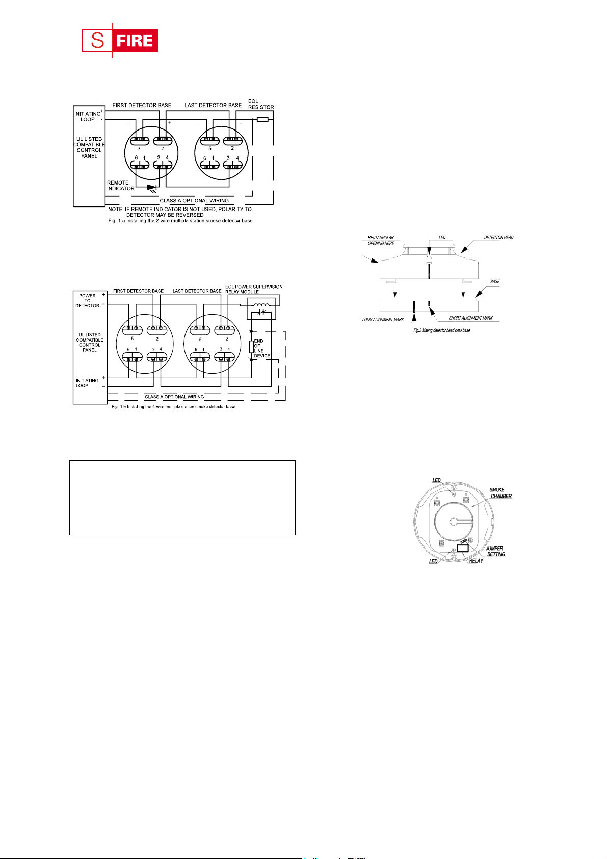
TYPICAL WIRING DIAGRAM
Figure 1.a shows the typical wiring diagram of 2-wire
multiple-station smoke detector system.
DO NOT USE LOOPED WIRE UNDER
TERMINALS 2 AND 5 BREAK WIRE RUN TO
PROVIDE SUPERVISION OF CONNECTIONS
Figure 1.b shows the typical wiring diagram of 4-wire
multiple-station smoke detector system.
DO NOT USE LOOPED WIRE UNDER
TERMINALS 2 AND 5 BREAK WIRE RUN TO
PROVIDE SUPERVISION OF CONNECTIONS
WARNING
TO PREVENT DETECTOR CONTAMINATION
AND SUBSEQUENT WARRANTY
CANCELLATION, THE SMOKE
DETECTOR MUST REMAIN COVERED
UNTIL AREA IS CLEAN AND DUST FREE.
INSTALLING THE BASE
1. To insure proper installation of the detector,head to
the base, all the wires should be properly
addressed at installation:
(A) Position all the wires flat against terminals.
(B) Fasten the wires away from connector terminals.
2. If you use the jumper wire to connect the poles of
terminal 2 and 5 when testing the detector
loop's continuity, be sure to remove the jumper wire
prior to the installation of the detector head.
3. The end-of-line device shown in Figure 1.a & 1.b
should be compatible with the control unit. The
end-of-line supervisory relay used should list the rated
DC power voltage used.
4. Per UL listing, open area smoke detectors are
SF119 series
Installation Wiring Diagram
intended for mounting on a ceiling at least 6 inches
away from a wall or mounting on a wall between 4 and
12 inches away from a ceiling.
5. The base of smoke detector can be mounted directly
onto an electrical junction box:octagonal (3”, 3.5” or
4”), round (3”), and square (4” length) boxes without
using any type of mechanical adapters.
INSTALLING THE HEAD
1. Align the components as shown in Figure 2.
2. Mate the detector head onto the base and twist it
clockwise to secure it.
3. Do not install the detector head until the area is
thoroughly cleaned of construction debris, dusts, etc.
The maximum number of smoke detector installed in
the same loop is 30 units.
Fig. 2 Mating detector head onto base
ADJUSTMENT OF THE RELAY POSITION
4-wire type: Adjust the relay set-position for wiring unit to the
security monitoring system through the following steps:
1. The reset position for the relays is “normally open”
(NO), when powering all the relays.
2.
3.
To adjust the relay set point, use a screwdriver to
loosen the two screws on the back of the base.
Figure 3 shows a jump head next to the relay on the
PCB, adjust it to select either the “normally
closed” (NC) or the “normally open” (NO) positions.
Relay contact rating:
1A @30VDC,
0.5A @125VAC.
TESTING
1. All the alarm signal services, releasing device and
extinguisher system should be disengaged during the
test period and must be re-engaged immediately at the
conclusion of testing.
2. After powering the detector head for approximately
one minute, check if the red LED light is flashing
once every 1~3 seconds. If the red LED fails to
flash, it indicates that the detector is not functioning
properly or the possibility of having incorrect wiring.
Re-check the wiring or replace the detectorif
necessary.
Fig. 3 Schematic ofdetectorstructure
When front cover is open
3. Allow smoke from a cotton wick or a punk to enter the
detector’s sensing chamber for at least 10 seconds.
When sufficient smoke has entered the chamber, an
alarm signal would be triggered by illuminating the
LED. After the alarm is triggered, reset each
detector and/or control unit before attempting to
test the additional detectors in the same zone. If the
alarm fails in this step, it indicates a defective unit,
which would require service.
HEAT SENSOR TESTING
To test the detector, it should be subject to a flow of
warm air at a temperature between 284F and 356F
(140C and 180.C). Some domestic hair dryers can meet
this requirement. Proceed as follows:
1. Switch on the warm airflow and check that the
temperature is correct and stable.
2.
3.
Direct the airflow at the guard protecting the
thermistor. The detector should be triggered within 30
seconds.
When the alarm is on, immediately remove the
heat source and check that the detector’s red LED
is on. Reset the detector from the control panel.
4. If the detector fails to trigger the alarm within 30
seconds,it would mean that it should be returned to the
distributor for servicing to adjust its sensitivity.
5. After testing,check that the system is set for
normal operation and notify the appropriate authorities
that the testing operation is complete and the system
is active again.
NOTES FOR USING DETECTOR
The National Fire Protection Association (NFPA)
states that duct smoke detector must not used as a
substitute foropen area smoke detectors. Duct
smoke detectors are solely intended to use in the
air handing equipments for such purposes like
dampers or shutting down the air handing units.
NOT SUITABLE FOR INSTALLATION IN
AREAS WHERE AIR VELOCITIES EXCEED
300 ft/min.
MAINTENANCE
The recommended minimum requirement for detector
maintenance consists of an annual cleaning of the dust
from the detector head by using a vacuuming routine
compliant with the NFPA-72A standard.
CAUTION: DO NOT ATTEMPT TO REMOVE
THE SCREWS WHICHHOLDTHE ASSEMBLY
OF THE SMOKE-SENSING CHAMBER ANDPRINTED
CIRCUIT BOARD(PCB). THIS ASSEMBLYIS
SEALED FOR YOURPROTECTION ANDIS NOT
INTENDED TO BE SEPARATED FOR SERVICING BY
USERS. OPENING SUCH ASSEMBLY WILLVOID
THEWARRANTY.
REFER TO THE TECHNICAL BULETIN ISSUE
NO.STSD20080702S01, REV.D, July 02, 2008
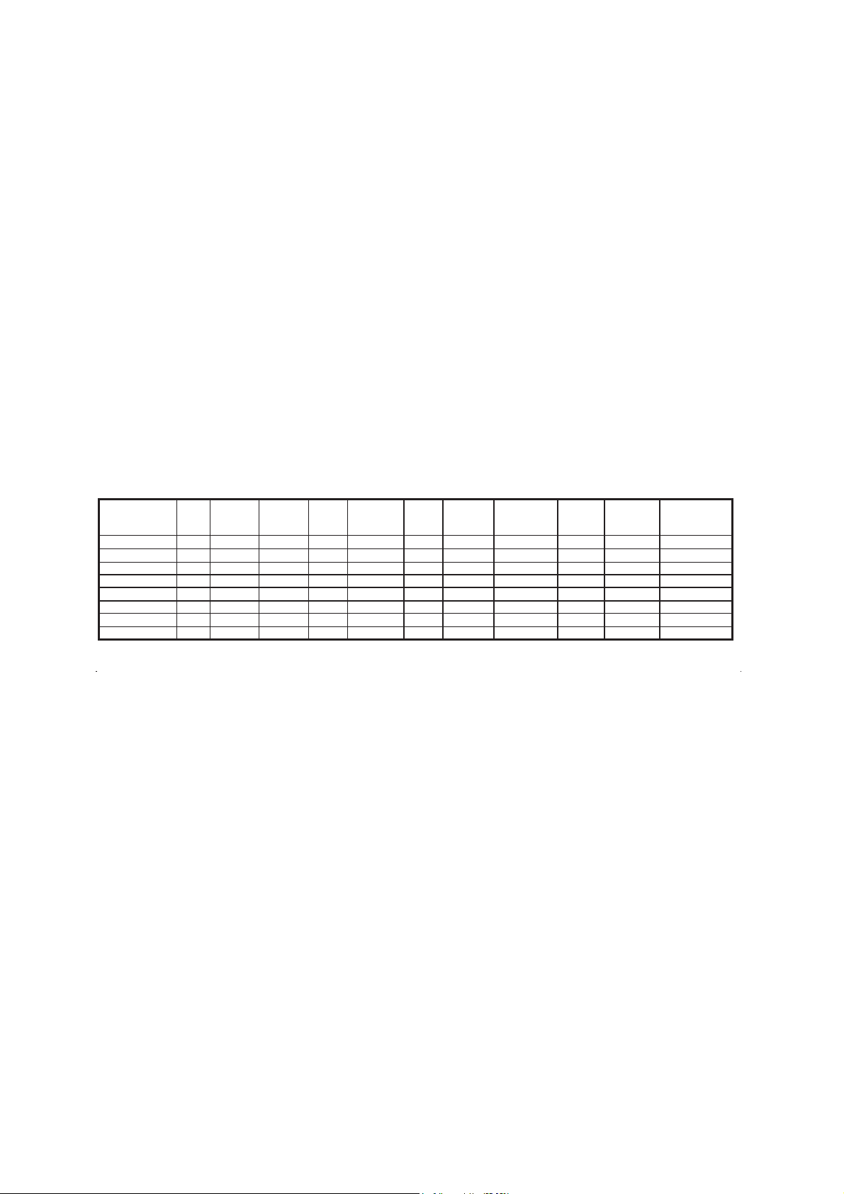
SPECIFICATION
Model
2/4
wire
Heat
Sensor
Setting
Voltage
DC
(Min./Max.)
Standby
Current
(Max.)
Alarm
Current
(12/24V)
Surge
Current
(Max.)
Start-Up
Time
(Max.)
Permissible
Current
(Max.)
Cycle
Time
Alarm
contact
Base
Model No.
SF119-4H(12V) 4 135±512V 80μA 30mA - 30 Sec. - 1-3 Sec. Form A P/N854001
SF119-4H(24V) 4 135±524V 80μA 45mA - 30 Sec. - 1-3 Sec. Form A P/N854001
SF119-4 (12V) 4 - 12V 80μA 30mA - 30 Sec. - 1-3 Sec. Form A P/N854001
SF119-4 (24V) 4 - 24V 80μA 45mA - 30 Sec. - 1-3 Sec. Form A P/N854001
SF119-2HL 2 135±510.8~33V 80μA 22/55mA160μA30 Sec.80mA 1-3 Sec. — P/N854001
SF119-2L 2 - 10.8~33V 80μA 22/55mA160μA30 Sec.80mA 1-3 Sec. — P/N854001
SF119-2H 2 135±510.8~33V 80μA 22/55mA160μA30 Sec.80mA 1-3 Sec. — P/N852001
SF119-2 2 - 10.8~33V 80μA 22/55mA160μA30 Sec.80mA 1-3 Sec. — P/N852001
Remark: L- remote indicator output; H-Heat sensor; AR-Auto-reset; B-Sound
2-wire devicesare UL Recognized, the 4-wire devicesare UL Listed
This manual suits for next models
6
Other S Fire Smoke Alarm manuals


