Söring MBC-601 User manual
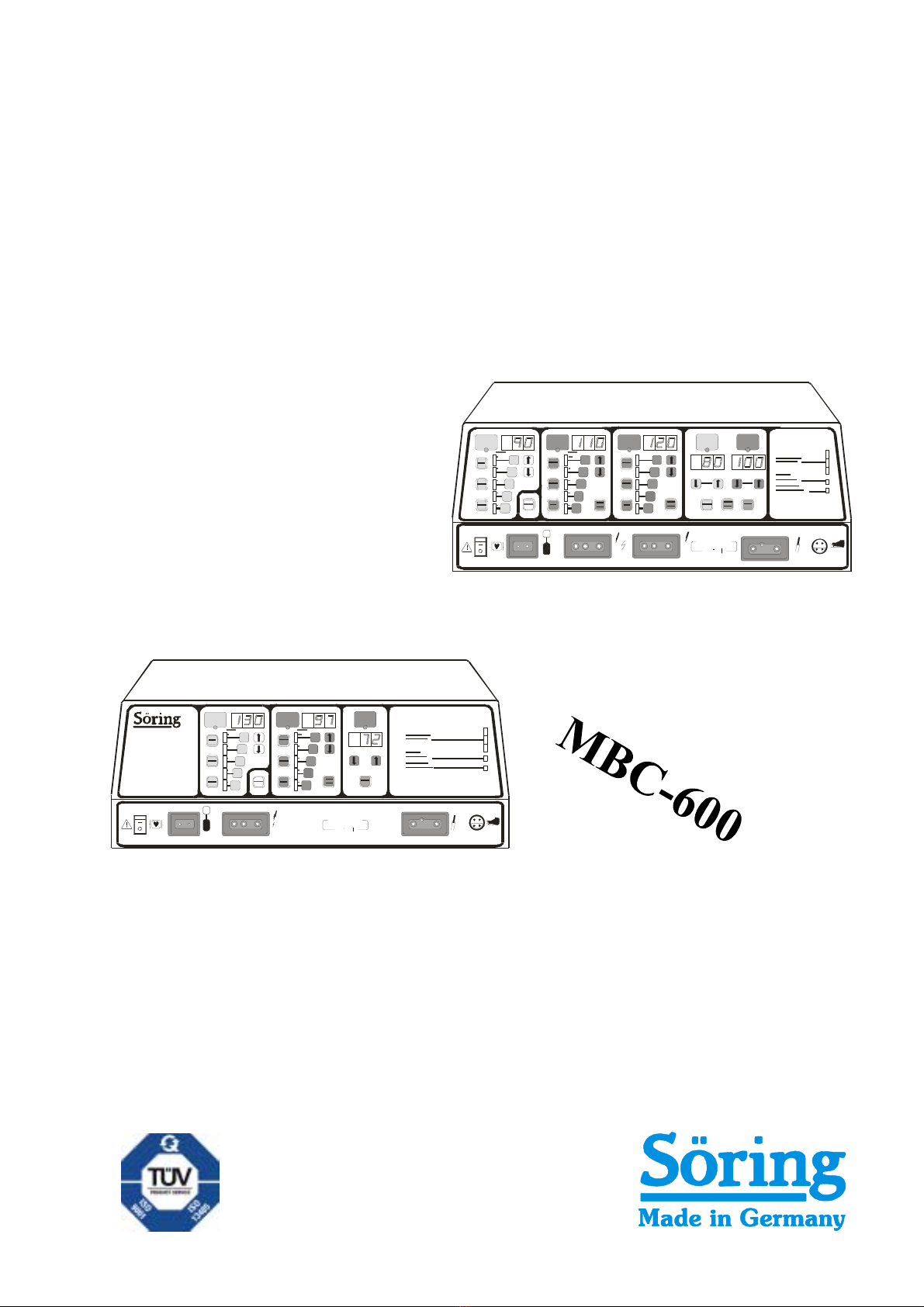
USERS MANUAL
Söring
MB C 6 0 1
Safety
Sicherheit
BIPO
Coag
BIPO
Cut
MONO
COAG2
MONO
COAG1
MONO
CUT
1
2
3
4
5
1
2
3
4
5
1
2
3
4
5
12
F
BIPO
COAG
MONO
COAG
MONO
CUT
1
2
3
4
5
1
2
3
4
5
Safety
Sicherheit
Sör ing
MB C 6 0 0
F
MBC-60
1

27/04/04 © Söring Users manual RF-units
1not valid for MBC600 -2-
Söring Inc
5009 Martin Luther King Jr. Freeway,
Fort Worth,
TX 76119
Söring GmbH
Medizintechnik
Justus von Liebig Ring 10
25451 Quickborn
Tel: 001-817-457-2200
Fax: 001-817-547-2201
E-mail: [email protected]
Tel: (+) 49 (0)4106-6100-0
Fax: (+) 49 (0)4106-6100-10
E-mail: [email protected]
BH-MBC-USA 04/2004
03-092 R3

27/04/04 © Söring Users manual RF-units
1not valid for MBC600 -3-
Contents
1. Introduction .................................................................................................................5
2. Important notes regarding the operation of RF Surgery units .........................6
2.1. Operating of RF Surgery Equipment ................................................................................................6
2.2. User instructions ...................................................................................................................................6
2.3. Prescribed safety checks....................................................................................................................6
2.4. Medical Product Log Book..................................................................................................................6
2.5.How to keep the instruction manual and the medical product log book.................................7
2.6. Accident and damage report ..............................................................................................................7
2.7 Modifications and repairs.....................................................................................................................7
3. Physiological and physical fundamentals of RF Surgery..................................8
3.1. Heating effect of RF currents in biological tissue........................................................................8
3.1.1 Reaction of biological tissue to local overheating ...........................................................................9
3.2 Methods of RF Surgery and electrical Signal Shapes.................................................................12
3.2.1 Cutting...................................................................................................................................................12
3.2.2. Coagulation.........................................................................................................................................13
3.2.3. Electrodessication..............................................................................................................................13
3.2.5. Bipolar application technique...........................................................................................................14
3.2.5.1 Bipolar Automatic.........................................................................................................................................14
4. Patient safety.............................................................................................................15
4.1. Patient placement................................................................................................................................15
4.2. Attachment of patient electrode......................................................................................................15
4.4. Current carrying cables .....................................................................................................................18
4.5. Dangers from inflammable and explosive media........................................................................19
4.6 Instructions for special applications...............................................................................................19
Arrangement of Switches, Sockets and displays of MBC 601.........................................................20
Arrangement of Switches, Sockets and displays of MBC 600.........................................................21
5.1. Description of controls and indicators..........................................................................................22
5.1.1 Description of the Safety Equipment................................................................................................27
5.2 Putting the equipment into operation .............................................................................................28
5.2.1 Description of operational facilities..................................................................................................28
5.2.2 Preparation of equipment...................................................................................................................28
5.2.3 Switching on the equipment...............................................................................................................28
5.2.4. Adjustment of function fields............................................................................................................29
6. Accessories (extracts).............................................................................................30
7. Cleaning, maintenance, disinfection and sterilization .....................................31
8. Technical Data...........................................................................................................32
9. Technical safety checks..........................................................................................35

27/04/04 © Söring Users manual RF-units
1not valid for MBC600 -4-
9.1 Intervals...................................................................................................................................................35
9.2 Extent.......................................................................................................................................................35
9.3. Description of special checks..........................................................................................................35
9.3.1. Check of controls and indicators .....................................................................................................35
9.3.2. Check of handpieces and footswitches ..........................................................................................35
9.3.3. Check of RF generators and safety devices..................................................................................36
9.3.4. Power measurement..........................................................................................................................36
9.3.5. Current Leakage test.........................................................................................................................36
9.3.6. Test of handpiece allocation relay...................................................................................................36
9.3.7. Test of patient electrode recognition ..............................................................................................36
Remarks ..........................................................................................................................37
27/04/04 © Söring Users manual RF-units
1not valid for MBC600 -5-
1. Introduction
This operating manual describes the function and handling of the Radio Frequency Surgery
Equipment MBC. The manual serves as an instruction reference and should be read thoroughly
before operating the equipment. Only then can the correct handling of the equipment be assured.
In case of incorrect handling no liability will be taken on by the manufacturer.
MBC's are RF surgery equipment conforming to DIN IEC 601 part 1, respectively EN60601-1
utilized only for rooms for medical use. Every important function is controlled and supervised by a
microprocessor.
The MBC units, in MONOPOLAR MODE, are meant for the use in general surgery and
gastroenterology. In MONOPOLAR MODE, operations on the heart, eyes and in the brain
(neurosurgery) are not admissible!!!
This equipment has not been developed for continual operation (constant power supply for a
longer period). The period for use fulfills the demands for operation of the EN60601-2-2 (10s load,
30s break).
This RF Surgery unit meets the requirements of the (EMC) guideline 93/42/EWG of the European
Community and is therefore labeled with the
0123
sign!
Before starting operation the appropriate handpieces must always be checked for external
damage.
The Söring Company only accepts liability if accessories from the Accessories Order List
were used!!!
At the end of the normal life cycle of the unit it should be taken to either a legitimate electronics
disposal site or to the Söring Company.
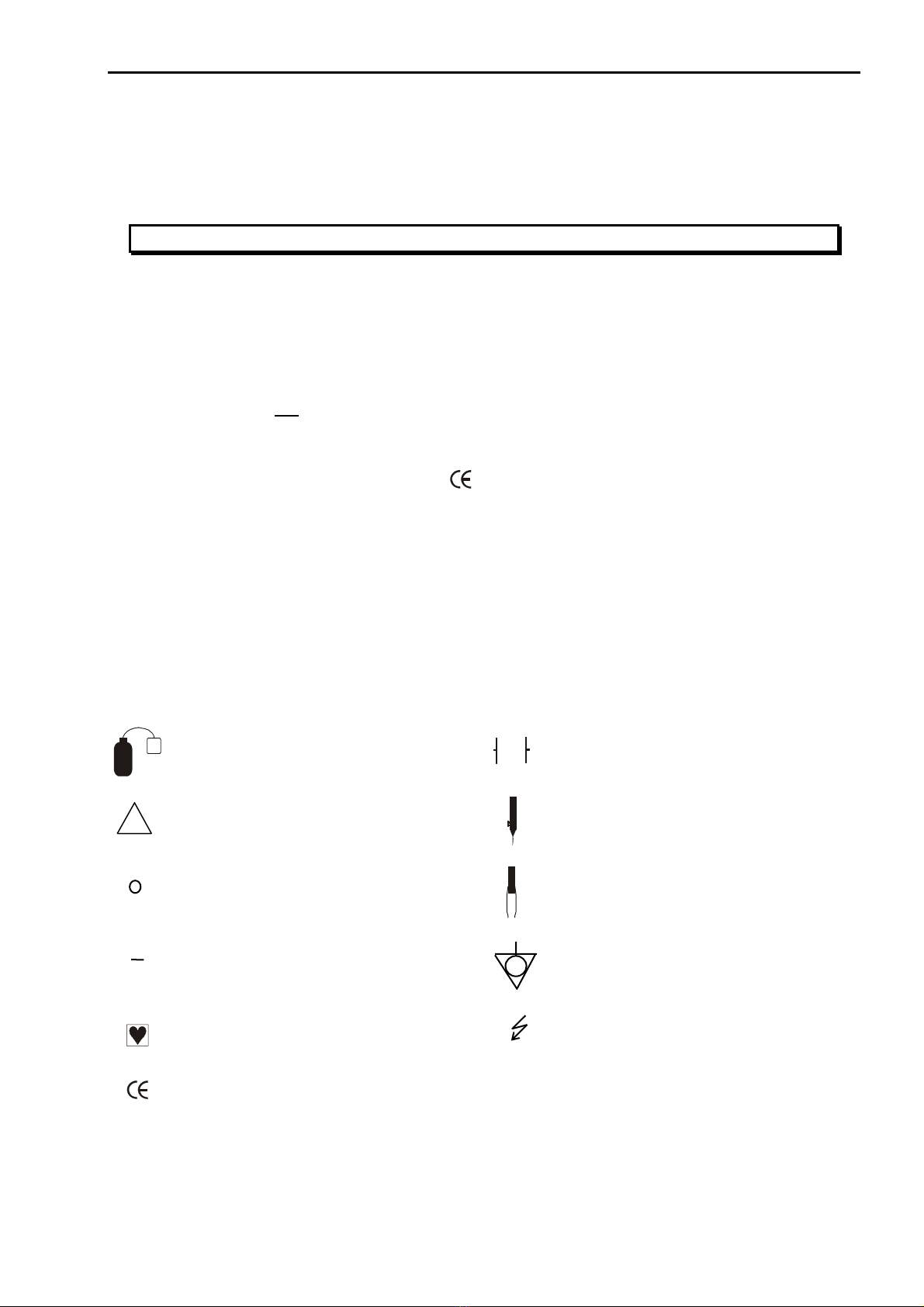
Symbols Used
F
Patient electrode (when RF applied patient
electrode- electrode insulated against earth) Defibrillator save
Attention!, see also covering
documents Monopolar Cutting & Coagulation
Off (separation from main power
supply)
Bipolar Cutting1and Coagulation
On (connection to main power supply) Potential equation pin
type CF Attention high voltage
0123
CE label acc. To 93/42/EWG
!

27/04/04 © Söring Users manual RF-units
1not valid for MBC600 -6-
2. Important notes regarding the operation of RF Surgery units
During operation of RF surgery equipment disturbances of other electronic devices
may occur due to generated interfering signals.
2.1. Operating of RF Surgery Equipment
The user is only allowed to operate such RF Surgery Equipment after the manufacturer or the
distributor has:
1. Checked the equipment for faultless function at the location of operation and
2. Introduced the person responsible to the operation of equipment according to the instruction
manual.
2.2. User instructions
RF Surgery equipment is only to be operated by persons, who have been introduced to the
correct use of the equipment according to the instruction manual. Only people with sufficient
knowledge of how to handle the equipment and practical experience are allowed to instruct
others.
If such instruments are combined with additional equipment, the instruction of the operating
personnel must be extended to the combination and its special functions.
2.3. Prescribed safety checks
The user of the RF Surgery unit must carry out the prescribed safety checks within the period
stipulated and to the extent required. The extent and the periods for safety checks for RF
equipment must be performed according to manufacturer's recommendations regarding extent
and periods of inspections during servicing.
Safety checks of the technical protocols must be assigned only to those who have the
appropriate education, the knowledge, and the experience gained during their practical work
enabling them to carry out those checks accordingly. The safety check should be performed in
a distraction free environment. If failures are found during safety checks, which may endanger
patients, staff or third parties, the technician must immediately inform the authority responsible
for the use of the instrumentation.
2.4. Medical Product Log Book
The supervising operator of RF Surgery units must keep a medical product log book. Other
documentation is equivalent to the medical product log book, as long as it fulfills the
requirements of the medical product log book to the same extent and is available for the user
at any time.
The following entries are to be made in the medical product log book
1. Date and time of the function test before operating the equipment for the first time.
2. Date and time of instruction, as well as the names of the instructed persons.
3. Date and time of performing required safety checks and maintenance as well as the name of
the person or the company performing these checks.
4. Date, time, kind, and consequences of failures and of re-occurring similar operation
mistakes.
A copy of the CE certificate must be kept with the medical product log book.

27/04/04 © Söring Users manual RF-units
1not valid for MBC600 -7-
2.5.How to keep the instruction manual and the medical product log book
Instruction manuals and equipment books for RF surgery equipment must be kept, so that they
are always accessible to persons commissioned to use the equipment.
The responsible authority may ask to look at these books at any time.
2.6. Accident and damage report
Function failures or breakdowns of medical equipment causing bodily injury must be reported
immediately to the authority responsible.
The hospital must report the incident to the FDA and include all of the pertinent information as
required by that agency. Suggested information to be gathered by the hospital includes the
following:
1. What caused this event?
2. Was the equipment in proper operating condition
3. If repaired, does danger no longer exist.
4. Has new knowledge been gained which will make other or additional safety provisions
necessary?
2.7 Modifications and repairs
Modifications and repairs must not reduce the safety of the equipment and accessories for the
patient, user, or the environment. Therefore, modifications and repairs to this equipment must
only be carried out by the manufacturer or by persons explicitly authorized by Söring. If non-
authorized persons perform unqualified modifications and repairs to the equipment or
accessories, the manufacturer will not accept liability. Furthermore in this case the warranty
expires.

27/04/04 © Söring Users manual RF-units
1not valid for MBC600 -8-
3. Physiological and physical fundamentals of RF Surgery
Thermocautery as an aid to mechanical operation techniques began many years ago with the
application of heated metal tools to wounds to control bleeding. The technique was found to be
very effective. Later the use of electrical power to effect electro-cauterization and cutting of
tissue was the next logical step. RF Surgery is the use of high frequency alternating electrical
current (frequency higher then 300 kHz) with the purpose of alteration or destruction of cells and
for cutting tissue. It is used for tissue removal and cauterization in connection with mechanical
operation techniques. The tissue cauterization and cutting effects are accomplished by a
combination of heating through the electrical resistance offered by the biological tissue and
through the heating of the electrode.
3.1. Heating effect of RF currents in biological tissue
The heat production is mainly a result of the fact that biological tissue acts as an electrical
resistor for frequencies normally used during RF surgery and that as an electrical resistor
biological tissue heats up when electric currents flow through.
The amount of heat developed is therefore dependent on the current and the resistance of the
conductor (the biological tissue) put up by the patient.
From the electrical point of view the patient is the conductor. The material of the conductor and its
geometrical shape influences the resistance of this conductor. In this connection a comparison of
specific resistance of metallic conductors and biological tissue is of interest. Table 3.1 clearly
shows that the specific resistance of metals is much smaller than that of biological tissue. As a
result, in a closed current loop of metallic conductors and biological tissue of equal cross
sectional area the biological tissue heats up significantly more. As can be seen in the table below,
different biological tissue types offer a wide range of electrical resistance and thus are affected
differently by the applied RF signal. The MBC internal circuitry automatically senses the resistivity
and adjusts the RF signal accordingly for the best results.
Biological Tissue [
Ω
.cm]
(in the range 0.3 to 1 MHz) Metal [
Ω
.cm]
blood 160
muscle, kidney, heart 200
liver, spleen 300
lung 1000
fat 3300
silver 0,0000016
copper 0,0000017
gold 0,0000022
aluminum 0,0000029
Table 3.1: Comparison of specific resistance of metals and biological tissue
The desired thermal effect should be accomplished within a small area in front of the active
electrode. Conditions for RF heating are areas with small cross-sectional area and low electrical
conductivity.
The actual temperature at the contact area between the active electrode and tissue results from
the energy balance. The energy supplied is influenced by:
-Current per area (dependent on specific resistance of the tissue and the shape of the
electrode).
-Effective time (the time that the RF current acts on the tissue area as determined by the
electrode type and velocity of the electrode over the tissue).
-Current shape (full power, alternation of power, or changing power levels)
The conducted heat is influenced by:
-The condition of the tissue, particularly at any given moment of the application cycle because
the local thermal conductivity changes as tissues are destroyed.
-Temperature, because additional energy is needed for vaporization of tissue fluid.
27/04/04 © Söring Users manual RF-units
1not valid for MBC600 -9-
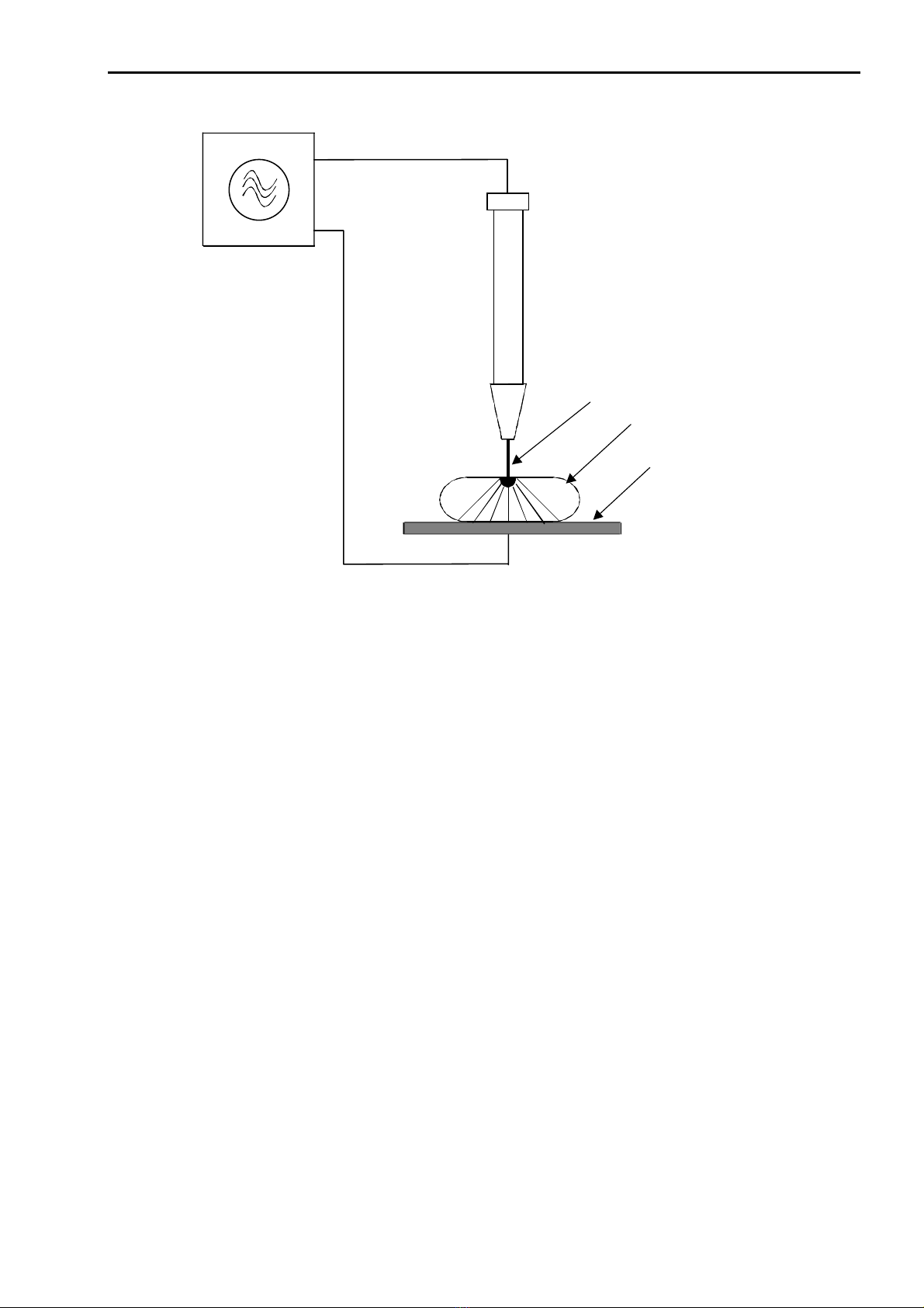
HF-Generator
R
F-generator
Aktive-Elektrode
active electrode
biologisches Gewebe
biological tissue
Neutral-Elektrode
P
atient electrode
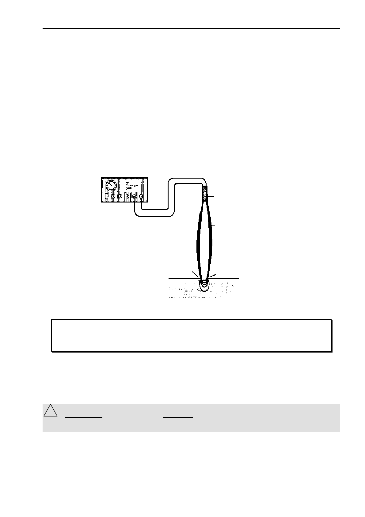
Fig 3.1. Shows the principle of RF Surgery
3.1.1 Reaction of biological tissue to local overheating
If RF voltage (continuous sine signal) reaches a certain upper limit, an arc will occur at the
contact zone of the active electrode to the tissue. This leads to a quick heating of the intercellular
fluid. This vaporization of the intercellular fluid results in a bursting of the cells and the tissue
looses its cohesion i.e., the electrode cuts.
Lower RF voltages (below 150veff) lead to a slower heating of the tissue, resulting in coagulation
with no tissue separation.
Short RF impulses with high voltage lead to a build-up of sparks together with a strong surface
coagulation.

27/04/04 © Söring Users manual RF-units
1not valid for MBC600 -10-
active electrode
horny layer
p
apilliary body
s
ubcutaneous fatty tissue
musculature with connective
tissue
vessel
bone
Fig 3.2
Schematic representation of a melt-cut: Depending on the value of resistance of the
different effected tissue the coagulation seam (the heat damage) is more or less
widespread; broader at the horny layer than in the papillary body or the subcutis, even
wider in the fatty tissue. In the musculature the heating effect melts deeper into the gaps of
the connective tissue. Within a cut vessel the blood retracts and the intima is damaged
from the different wall layers over a large area. In bones, the heating effect spreads along
both sides of the periosteum and spreads only slowly deeper below the tip of the electrode.
If, however, the heat developed is extended to a larger area due to a larger contact surface
between active electrode and tissue, boiling of the tissue fluids occurs together with widespread
albumin coagulation. Depending on the used current intensity either depth coagulation (see Fig.
3.3) or a surface coagulation (see Fig. 3.4) with eschar generation is achieved. Due to bad
thermal conductivity of eschar, heat transfer, especially into the depth, is prevented by eschar
formation.
27/04/04 © Söring Users manual RF-units
1not valid for MBC600 -11-
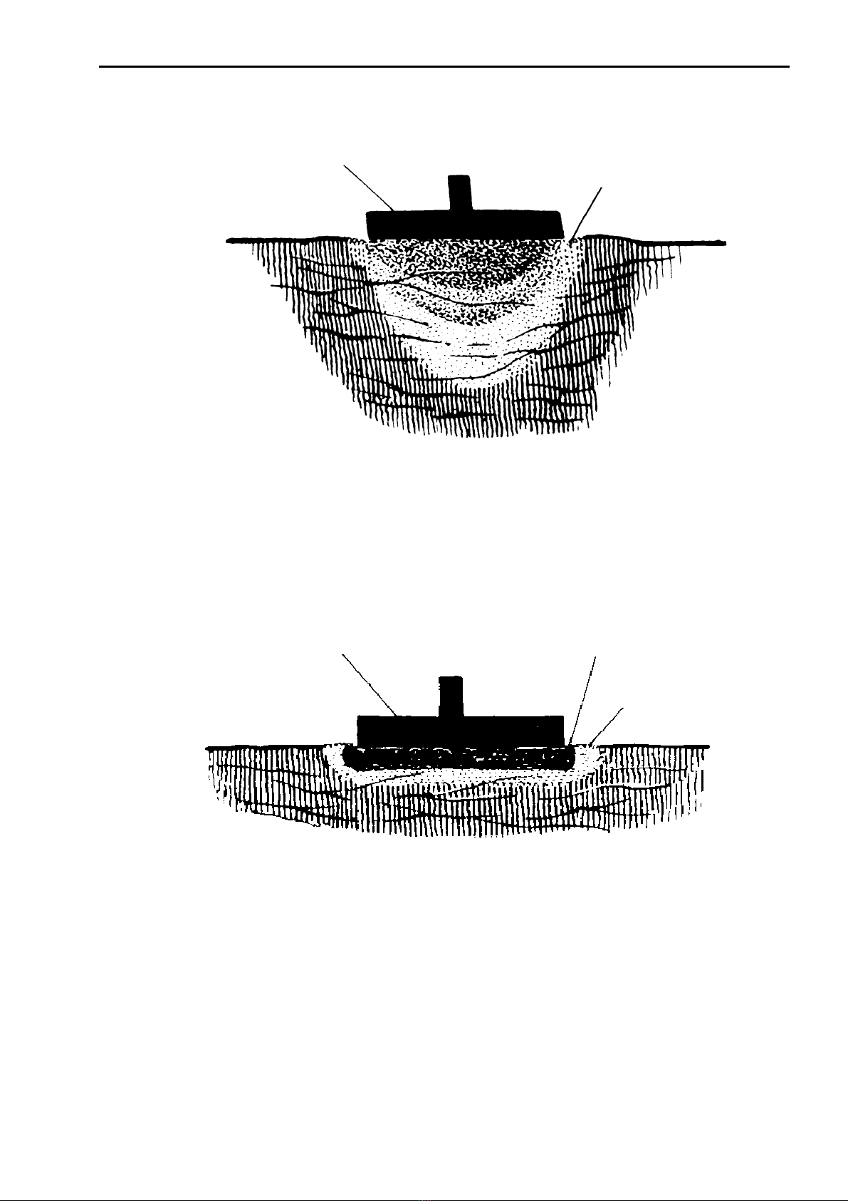
Fig. 3.3
Schematic representation of electro-coagulation on a homogenous tissue: The boiling extends to
a depth somewhat larger than the diameter of the electrode. It is strongest underneath the
electrode. At the surface it also extends to the surroundings of the electrode (rim effect).
Fig. 3.4
Schematic representation of electro-coagulation with generated eschar: In this case the current
value used for electro-coagulation is too high. Close to the electrode a coagulation of tissue is
initiated so rapidly that eschar is created, the isolating effect of which prevents a deeper
electro-coagulation. Due to eschar the electrode sticks to the tissue.
active electrode
coagulated tissue
active electrode
g
enerated eschar
coagulated tissue

27/04/04 © Söring Users manual RF-units
1not valid for MBC600 -12-
3.2 Methods of RF Surgery and electrical Signal Shapes
Cutting and coagulation modes of RF surgery depend in part on the shape of the sine wave of the
electrical current. The frequency is remains around the 350 kHz range but the current amplitude
(power) is changed to meet the surgical demands. A cutting current is a continuous sine wave.
The amplitude is varied to accommodate the tissues being cut as each tissue type has a different
electrical resistance. A coagulating current has a diminishing sine wave form repeated over
intervals of time (parts of a second) and at varying sequence frequencies to achieve selected
levels of coagulation. In the initial phase of a coagulation event the amplitude of the current is
high and then falls to zero or almost so. If such a current could be heard it might resemble the
sound of a ringing bell. See Figure ZZ.
3.2.1 Cutting
The cutting effect is based on the principle of cellular rupture. This is accomplished by a rapid and
locally limited temperature rise causing an explosion-like vaporization of intra and extra cellular
fluids, which ruptures cells and fractures cell connections. Under ideal conditions no coagulation
occurs at the cut and the surfaces of the cut do not show the typical light color of a coagulation
seam.
Principle of cell destruction
The shape of the electrode influences the cutting action and the kind of cut in electrotomy.
Basically, cutting electrodes should have a tissue contact area as small as possible in order to
obtain a high current density within a narrow space.
Loop or Ribbon Electrode
Knife or Lancet Electrode
Needle or Wire Electrode
Fig 3.5 Shapes of electrodes
Needle or wire electrodes are particularly useful for fine cuts where no or only minor coagulation
is wanted. They present a very small tissue contact area allowing a high current density needed
for fine cuts. With higher power the electrode will overheat and tissue will stick to it.
Knife or lancet electrodes resemble conventional scalpels with respect to their geometrical shape.
The cutting action, however, is based on the above-mentioned principles and not on mechanical
action. The leading edge of a knife has a small contact area where high current density can be
produced for a fine cut, whereas, the broad sides of these electrodes achieve coagulation along
the cut surfaces. Due to the relatively larger surface, compared with the needle electrode, more
RF power is required. However the heating of these electrodes is lower due to their higher thermal
capacity.
Loop and ribbon electrodes are mainly used for the cutting tissue by in slicing. A major application
of this so called “hollow-cut“ is the TUR (Transurethral Resection) in urology. Further parameters
which influence the quality of the cut are the cutting velocity, the condition of the tissue and the
shape of the current.

27/04/04 © Söring Users manual RF-units
1not valid for MBC600 -13-
smooth
cut Cut, rich of
coagulation Cut with eschar
Fig. 3.6
The smooth cut is largely comparable to the cut with a conventional scalpel, i.e. the cutting
surfaces are only slightly colored. This cutting mode is achieved with unmodulated RF-current and
by carrying-out the cut quickly.
A reduction of cutting speed gives a more coagulated cut even to the point of eschar with enough
speed reduction. The same result is achieved when using a pulse modulated RF current with the
same average power.
The power necessary for performing a RF cut depends on the shape of the electrode, type of
tissue and its resistance. If the power is too low, no cell rupture takes place and the tissue sticks
to the electrode. If the applied power is too high, spark discharges between electrode and tissue
are possible which causes carbonization of the cut surfaces.
3.2.2. Coagulation
For coagulation the tissue is heated more or less to such a degree that no cell rupture occurs.
The temperature for coagulation is above 50°C. This temperature leads to a coagulation of the
intra- and extra-cellular albumin (boiling of tissue). Perforated blood vessels contract so far that
the vessel is totally closed and no blood flows out. In order to obtain this effect, the electric
current must heat the tissue at a sufficiently slow speed so that the intra- and extra-cellular fluids
are vaporized without destroying the cell membranes. By this loss of fluid the cells contract and
the cell membranes are welded together.
This kind of coagulation is often called contact coagulation because the electrodes (shapes are
balls or plates) are brought into direct contact with the tissue. A supply of RF current causes a
light coloring of the tissue and a flow out of tissue fluid due to coagulation of cellular albumin.
3.2.3. Electrodessication
Electrodessication is a special mode of coagulation and is nowadays called Spray coagulation. By
means of a very high RF voltage, sparks or arcs between electrode and tissue surface are
27/04/04 © Söring Users manual RF-units
1not valid for MBC600 -14-
generated and no direct contact is necessary. The spark over causes an extreme temperature rise
in the tissue areas close to the surface and destroys them (surface coagulation, eschar,
carbonization). Electrodes with a small area like small ball or needle electrodes are used.
The necessary high voltage with moderate RF power is reached by high pulse modulation. Peak
voltages up to 9kvpp are obtained by this method.
Spray coagulation is mainly used for a quick and widespread coagulation of tissue e.g. with
seeping hemorrhage. It should be noted that the frequently generated eschar causes bad healing
and after-bleeding.
3.2.5. Bipolar application technique
With bipolar application the RF current does not flow through the body of the patient but directly to
a second adjacent electrode of the surgical instrument (e.g. a tweezers leg). The advantage is
that the RF current only flows in an area where the surgical effect is wanted so that damage to the
surrounding tissue is largely avoided. Further advantages are the low power requirement and a
low disturbance effect (e.g. on measurement equipment). Fig. 3.8 shows a schematic
representation of bipolar application technique.
Isolation
Insulation
Isolierter
Pinzettenschenkel
Insulated Tweezers’ leg
Pinzettenspitze als
„Neutralelektrode“
Tweezers’ Tip as
„
Patient electrode“
Pinzettenspitze als
„Aktivelektrode“
Tweezers’ Tip as
„
Active electrode“
Fig. 3.8
This equipment provides the application techniques bipolar cutting1and bipolar
coagulation. As described in the previous chapters 3.2.1 and 3.2.2 a continuous
signal is also used for bipolar cutting. The coagulation occurs with a lower RF
voltage.
3.2.5.1 Bipolar Automatic
When the automatic function of bipolar been selected, the equipment switches on and off auto-
matically for coagulation of tissue as soon as a sufficient tissue contact between the tweezers
legs has been recognized by resistance measurement. If required the system can be switched off,
so that the bipolar instruments can be activated by the footswitch. (see also chap. 5.1. point 7)
ATTENTION: Do not use Bipolar-Automatic-Mode (14) together with TissueLink Bipolar fluid
supported instruments. The irrigation fluid could disturb the recognition of the automatic function!!!
TissueLink fluid supported instruments have to be used only without activated bipolar automatic!
!

27/04/04 © Söring Users manual RF-units
1not valid for MBC600 -15-
4. Patient safety
The power output should be reduced to a value as small as possible in order to
obtain maximum patient safety with the application. Apparent low output of the RF
surgical equipment to function correctly at the normal operating settings may
indicate faulty application of the patient electrode and its contact in its connections.
4.1. Patient placement
With applications of RF surgery equipment any contact of the patient with grounded metal parts
has to be carefully avoided. In order to ensure this, the following points must be observed
- The patient shall not touch any piece of metal (i.e. OR table or any other metal parts). If
necessary, insulating arm or leg cuffs must be put on.
- Conductive respirator hoses must not lay in contact with the patient.
- The patient must not be laid down on moist sheets.
- Excretions of the body such as perspiration, secretions, blood and so on, liquids put on
for cleaning purposes, or applied liquids like infusions and so on, must not soak through
the dry sheets. If necessary, it must be possible to suck it off immediately and
thoroughly in order to avoid the gathering of liquid beneath the patient.
- Urine secretions must be drained via catheter.
- Areas with strong secretion of perspiration, extremities lying close to the body or areas
where skin touches skin must be kept dry by sheet covers.
- Anesthesia must be adjusted so that strong secretion of perspiration will be avoided.
Liquids of any kind must not be sprayed, spilled or used in ample quantities in order to
avoid its collection underneath the patient.
4.2. Attachment of patient electrode
This RF surgery equipment is provided with a patient electrode monitoring, which
checks the correct attachment of the patient electrode by measuring the transfer
resistance between the patient electrode and the patient tissue. For this
measurement the use of a split patient electrode is necessary. Although the use of an
undivided patient electrode is possible the manufacturer does not recommend it.
In order to apply the patient electrode carefully and safely to the patient the following shall be
observed:
- If an undivided patient electrode is used the monitoring circuit only checks the
connection between patient electrode and equipment. However no monitoring takes
place if the patient electrode is connected to the equipment but not attached to the
patient. It is the responsibility of the OR staff to check the reliable attachment of the
electrode to the patient.
- The patient electrode must be applied to the patient with its full surface in order to
achieve an even contact. Resting on bone projections must be avoided.
- Furthermore any metal parts inside the body (i.e., bone-nail, endo-prosthesis, bone
plates, screws, etc.) must be considered as they may influence the current supply.
- All external metal parts like rings, necklaces, bracelets, body piercing jewelry, etc. must
be removed.
- The patient electrode must be attached so that the current paths between active and
patient electrode are as short as possible and directed alongside or diagonal to the
27/04/04 © Söring Users manual RF-units
1not valid for MBC600 -16-
body, but under no circumstances at the thorax, because in this case the heart would
be located in the direct current path.
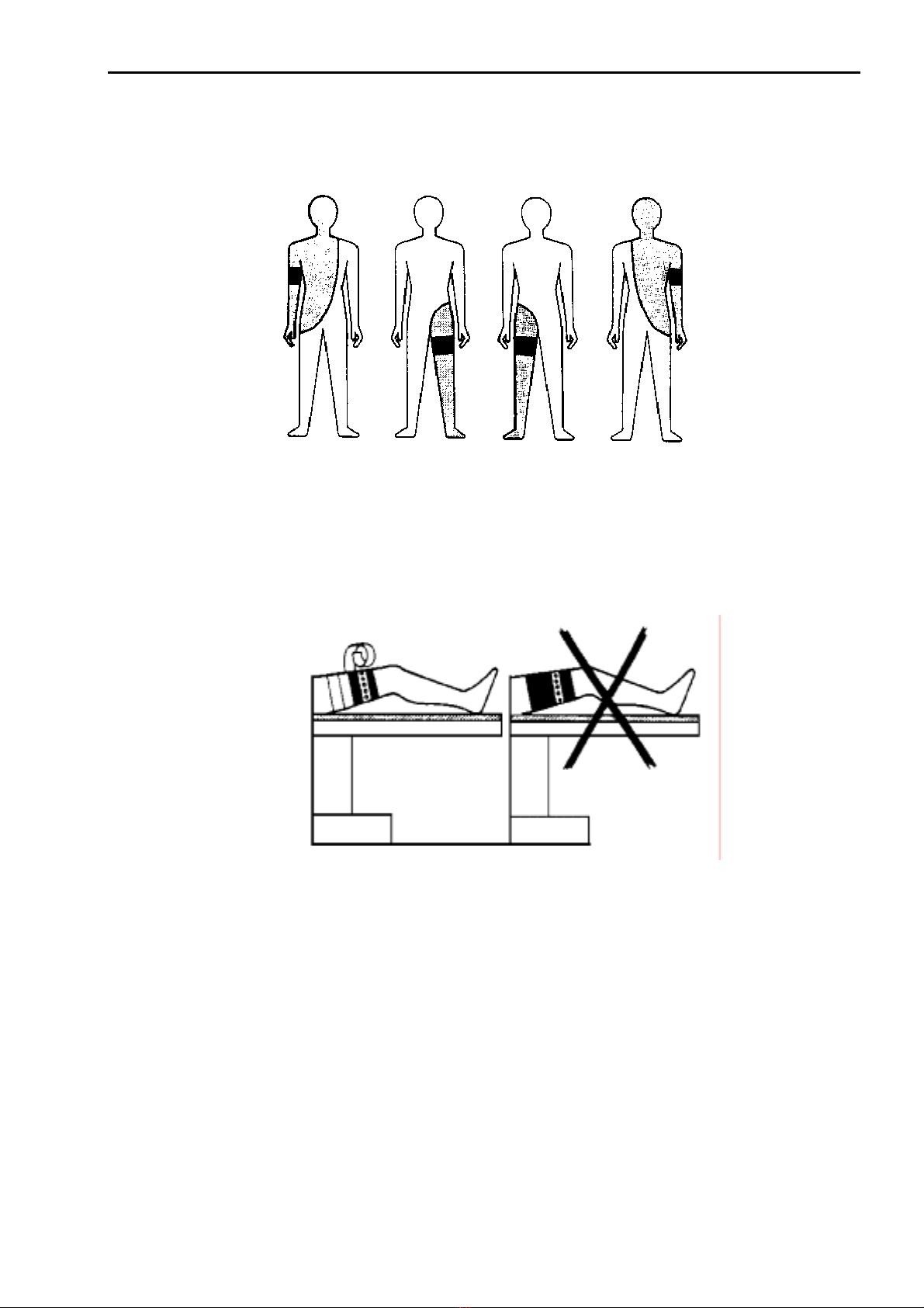
Fig. 4.1.Suggested placement of conventional patient electrodes and relevant operation fields.
-Permanent electrodes must be carefully secured with a flexible bandage or with elastic
bands. Wet towels, paste for electrodes, and so on are not to be put underneath. On the
other hand paste may be used with adhesive disposable electrodes, if drying out of the
paste is avoided. To insulate the patient electrode also against its surroundings it is to be
wrapped with a bandage after setting.
Fig. 4.2. Correct fastening
- When using self-adhesive disposable patient electrodes building-up of blisters beneath
the electrode may occur due to incorrect handling, wrong electrode paste, etc. Thereby
the contact surface is reduced and burns are possible.
- The contact surface for the patient electrode has to be cleaned, degreased, and freed
from strong growth of hair if necessary in order to obtain a low transfer resistance.
- Alcohol should not be used for skin cleaning because it dries out the skin and causes
increased transfer resistance at the contact area of the patient electrode.
- The contact area of the patient electrode should be moistened by carefully rubbing the
skin with a salt solution in order to obtain a good conductivity. Spraying should be
avoided because in this case salt solution could get underneath the patient.
27/04/04 © Söring Users manual RF-units
1not valid for MBC600 -17-
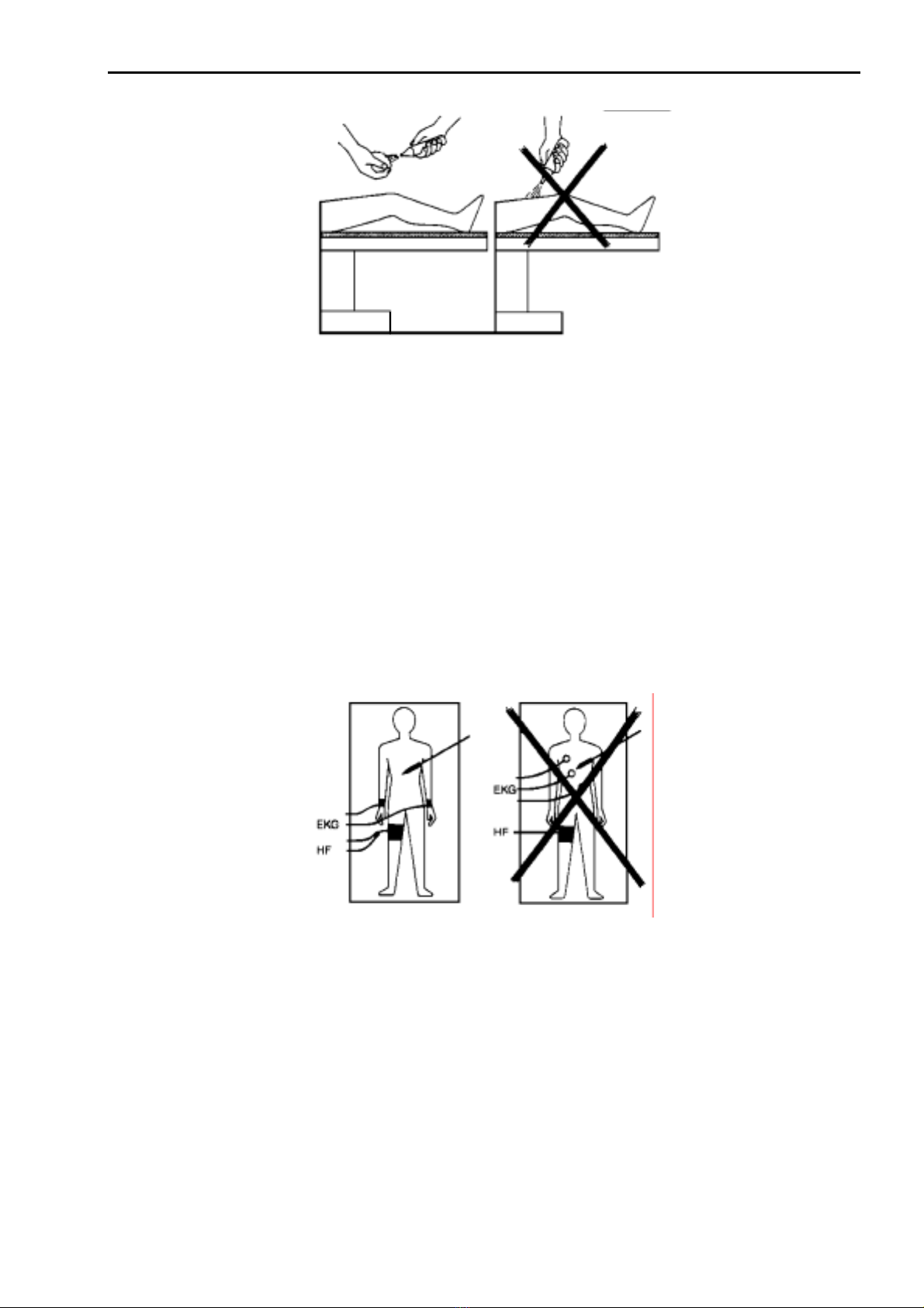
Fig 4.3 Moistening of body parts for fastening of patient electrode
- According to manufacturer’s specification the patient electrode must have a clean
surface free of corrosion and oxides in order to keep the transfer resistance as small as
possible.
- Furthermore the surface area of the patient electrode must be sufficiently large so that
no unacceptable heat will develop.
- In case of insufficient blood circulation the skin shall be massaged or brushed at the
contact area before applying the patient electrode. It should be mentioned that for long
lasting operations disturbed blood supply around the patient electrode might come up
again which leads to an increased transfer resistance.
- If the transfer resistance at the patient electrode increases during an operation, the
contact area heats up. Thereby, the skin dries out, the transfer resistance is further
increased, and burns may result.
Fig 4.5 Position of EKG electrodes for use in connection with RF surgery
- These recommendations are valid for normal EKG cables. Special EKG cables for RF
use are excepted.
In case RF surgery is applied at the thorax or at body parts above the thorax, the use of
unipolar electrodes for extremities according to “Goldberge” are recommended.
- In order to reduce possible fault currents, special EKG cables for RF use with current
limiting resistors of
≈
10 k
Ω
and a built-in RF choke should be used (see Fig. 4.6).
27/04/04 © Söring Users manual RF-units
1not valid for MBC600 -18-
Aktivelektrode
Active electrode
Neutralelektrode
Patient electrode
N-HF
N-RF
Strombegrenzungswiderstände
current-limiting Resistors
Aktivelektrode
Active electrode
N-EKG
N-ECG
EKG-unit
ECG unit
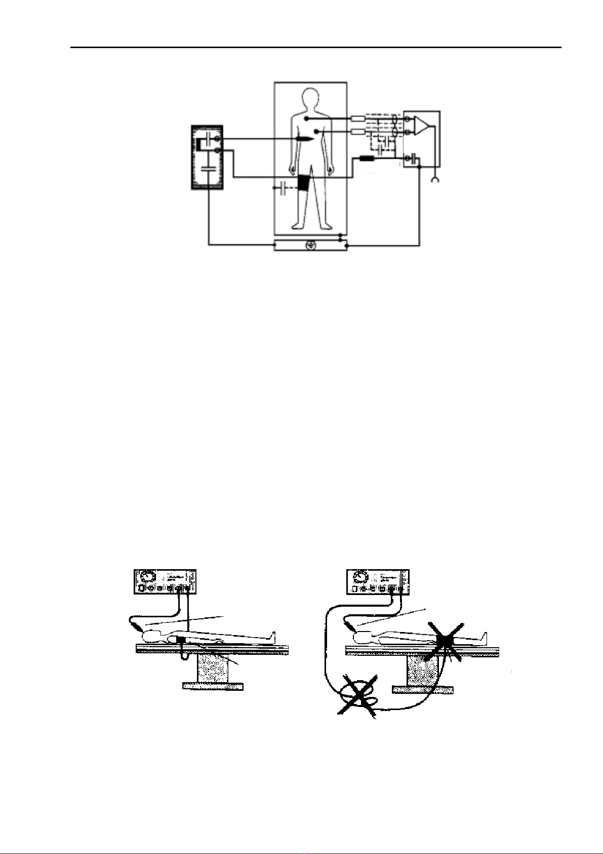
Fig 4.6 EKG cables with current limiting resistors
- Needle electrodes are not recommended for EKG monitoring. Because of their small
surface area the risk of burns is increased. Monitoring electrodes with areas as large as
possible should be used instead.
- For simultaneous operation of EKG and RF surgery equipment power outlets (230V~)
close to each other and connected to the same or adjacent power circuits should be
used in order to avoid dangerous current loops which may originate from outlets
situated far apart from each other.
4.4. Current carrying cables
(RF surgery equipment, monitoring electrodes etc.)
In RF surgery attention should be paid that electrode cables (active electrode, patient
electrode)
-are as short as possible
-are laid out without loops (see Fig. 4.7).
-are laid out so that they do not touch the patient or other cables (risk of capacitive current
coupling)
-are not conducted parallel to EKG cables (risk of capacitive current coupling) and
-do not present obstacles or stumbling risks to the OR staff.
Active electrode
Patient electrode
Active electrode
Patient electrod
Fig. 4.7Positions of cables and patient electrode in RF surgery

27/04/04 © Söring Users manual RF-units
1not valid for MBC600 -19-
4.5. Dangers from inflammable and explosive media.
In RF surgery development of sparks at the active electrodes cannot be avoided. If
inflammable or explosive agents for e.g. anesthesia, skin cleaning, degreasing and disinfection
or endogenous gases e.g. within the gastrointestinal tract are present, RF surgery must not be
applied because of fire and explosion hazard.
- For application of RF surgery all media necessary for the operation should therefore
neither be inflammable nor explosive, at least these media should be completely
evaporated and removed from the area of sparks (wait at least 10 seconds) before
switching on the RF surgery equipment.
- There is a risk of inflammable fluids gathering underneath the patient or in cavities of
the body (e.g. the navel). These fluids should be absorbed and removed.
- In order to avoid endogen gases the patient should be fed with an appropriate diet prior
to the operation. Furthermore the gastro-intestinal tract must be opened without RF
surgery.
- Explosive anesthetic agents (especially open anesthesia procedures) must not be used
in electro-surgical operation on the head, respiratory ducts, lungs and stomach.
- The units are not certified under AP classification! If combustible anesthetics, laughing
gas or oxygen are used in the thorax or head, these substances should be directly
sucked away or a unit of the AP class should be used instead.
4.6 Instructions for special applications
- If the operation with RF surgery equipment is extended over different parts of the body
the position of the patient electrode must be optimal for all areas of operation.
- For RF surgery equipment with two monopolar connections, problems will arise, when
two electro-surgical operations are performed simultaneously on the patient. The
surgeon should therefore decide whether it is really necessary to perform these
operations simultaneously, or whether they can be made one after the other.
- The simultaneous use of two RF surgery units on a patient is not allowed.
- When operations on small parts of the body are performed (e.g. vessels or hollow
organs), the use of bipolar technique could be advisable in order to avoid unwanted
coagulation at other parts.
- The simultaneous application of electro-surgical instruments and metal clips on hollow
organs with small cross-sectional areas is dangerous and may cause coagulation
necrosis.
- Directly grounded monitoring equipment, e.g. pulse monitoring clips, should not be used
as burns may arise.
- When RF surgery is applied to persons with implanted cardiac pacemakers or
electrodes, irreparable damage to the pacemaker or disturbance of the pacemaker
function together with ventricular flutter may happen. In case of doubt, the cardio-
logical department should be consulted.
- The patient is also endangered when a cardiac catheter is present during an electro-
surgical operation (micro-shock), because if the connection of the patient electrode to
the RF equipment is interrupted, part of the current may flow directly through the heart.
-Instruments/electrodes not in use must be kept a far distance from the patient!
27/04/04 © Söring Users manual RF-units
1not valid for MBC600 -20-
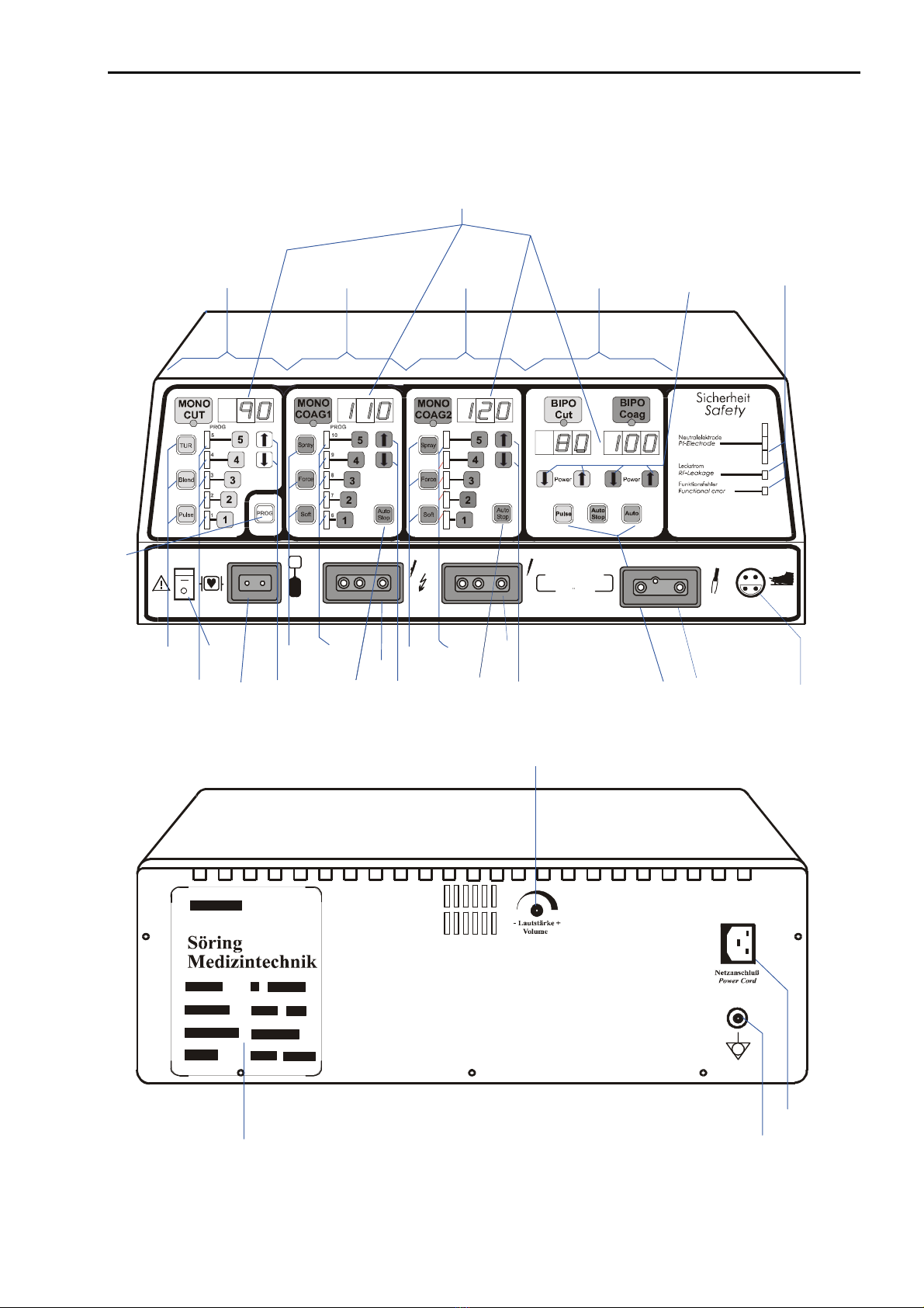
Arrangement of Switches, Sockets and displays of MBC 601
10
21
3
12
12 12
2
1
Söring
GmbH
MBC 6 0 1
12
F
15
14
15
14
10
14 11
3
9
16
19 17
18
20
4
865 6714
13
This manual suits for next models
1
Table of contents
Other Söring Medical Equipment manuals


Popular Medical Equipment manuals by other brands


PercuVision
PercuVision DirectVision Technical reference manual

MedaCure
MedaCure LX-BARI user manual

Alpha Modalities
Alpha Modalities A-Limb quick start guide

Bien Air
Bien Air DMX2 Plus instruction manual

Orliman
Orliman 2010-S INSTRUCTIONS FOR USE AND PRESERVATION

Pronk Technologies
Pronk Technologies SimSlim SL-8 Operator's manual