2
I.
OPERATING INSTRUCTIONS
A.
Entry
and
Security
DOORS
Two
keys
are
supplied with the
car.
Both
fit
the
ignition switch and all locks. The serial number
of
the key will
be
found engraved
on
a small
plastic lug
on
the key ring. Keep the lug and
make anote
of
the serial number in case the key
Is lost.
Both front side doors have lockable outside
handles.
These are locked and unlocked
as
follows:
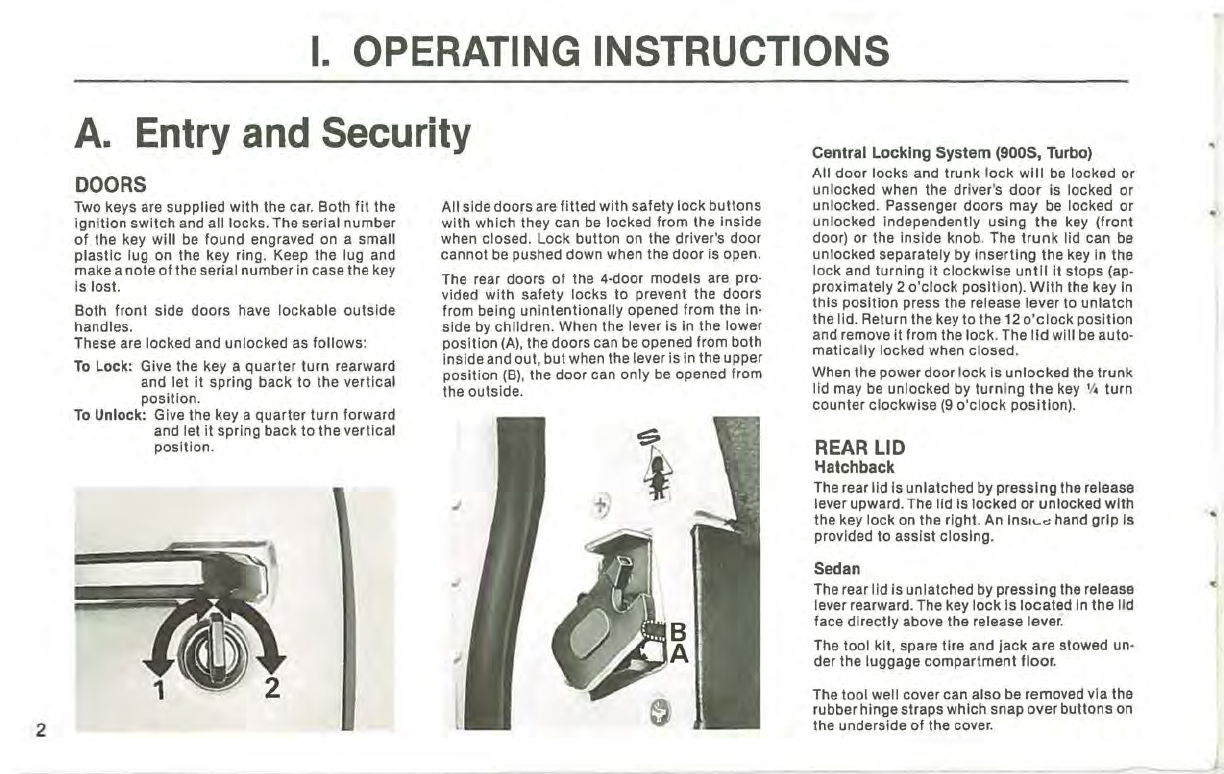
To
Lock:
Give the key a quarter turn rearward
and let
it
spring back to the vertical
position.
To
Unlock:
Give the key a quarter turn forward
and let
it
spring back to the vertical
pOSition.
All side doorsare fitted with safety lock buttons
with which they can
be
locked from the inside
when closed. Lock button
on
the driver's door
cannot
be
pushed down when the door is open.
The rear doors of the 4-door models are pro-
vided with safety locks to prevent the doors
from being unintentionally opened from the in-
side
by
children. When the lever is in the lower
position
(A),
the doors can be opened from both
insideand out, but when the lever is in the upper
position
(B),
the door can only
be
opened from
the outside.
Central
Locking
System
(9005,
Turbo)
All door locks and trunk l
ock
will
be
locked or
unlocked when the driver'S
door
is locked or
unlocked. Passenger doors may
be
locked or
unlocked independently using
the
key (front
door) or the inside knob_The
trunk
lid can
be
unlocked separately by
inserting
the key
In
the
lock and turning It clockwise
until
it stops (ap-
proximately 2
o'clock
pOSi
tion).
With
the key
In
this position press the release lever to unlatch
the lid. Return the key to the
12
o'clock
position
and remove it from the lock.The
lid
will
be
auto-
matica
ll
y locked when closed.
When the power door lock is unlocked the trunk
lid may
be
unlocked
by
turni
ng
the
key
'I
. turn
counter clockwise
(9
o'clock
pOSition).
REAR
LID
\-Iatchback
The rear lid Is unlatched by pressing the release
lever upward. The lid Is locked
or
unlocked
with
the key lock
on
the right.
An
Insl
....
'" hand grip Is
provided to assist closing.
Sedan
The rear lid is unlatched by pressingthe release
lever rearward. The key lock Is located
In
the lid
face directly above the release lever.
The tool kit, spare tire and jack are stowed
un
-
der the luggage compartment floor.
The tool well cover can also be removed via the
rubber hingestraps which snap overbuttons
on
the underside of the cover.
..