6
Sabine SWM4000 Smart Spectrum®Wireless
© 2010 Sabine, Inc.
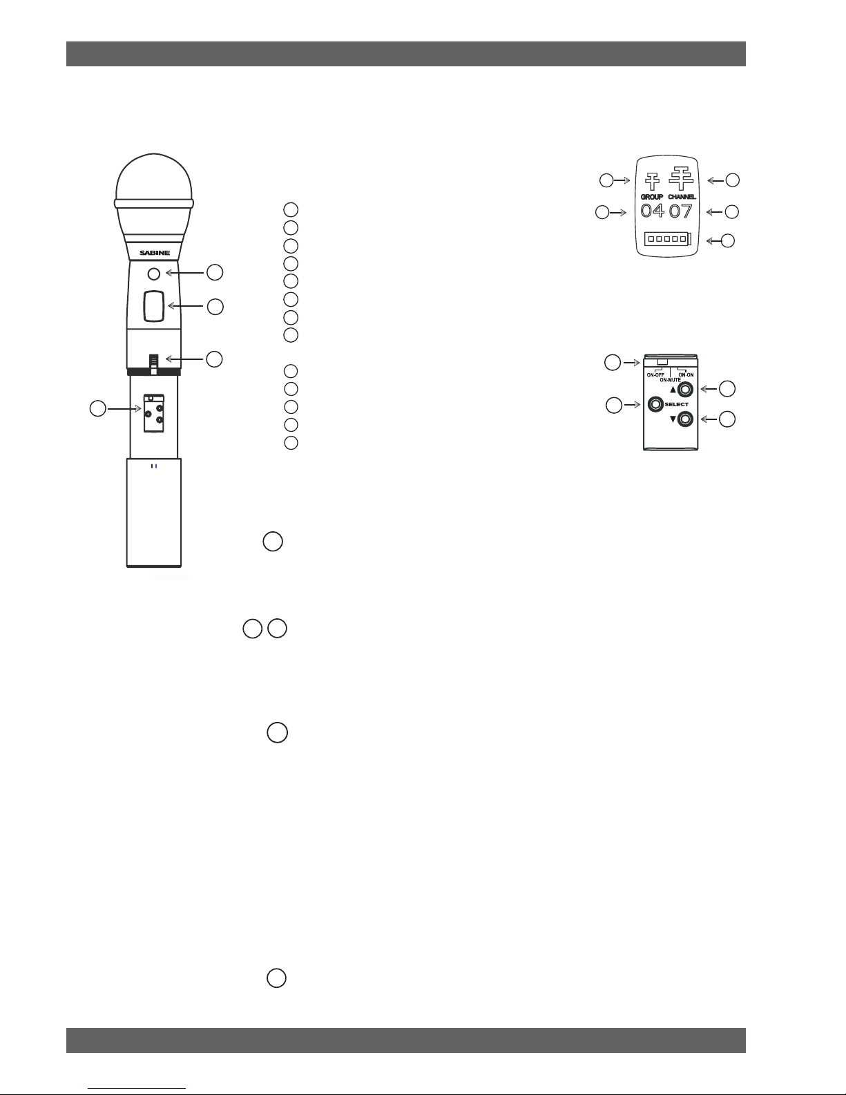
Select Button
Up Button
Down Button
Programmable Control of External Switch
Infrared Port
Transmitter LCD Screen
External Switch
Transmitter controls and battery compartments
Handheld Transmitter Controls
To Close: Turn the housing and push up until it
meets the threads, then screw on.
To Open: Unscrew lower portion of microphone.
Pull down as you continue to turn the housing.
Programming the Handheld Transmitter
Group/Channel:Press the Select button to enter Edit Mode, and repeat until the
GROUP indicator ashes. In this mode, the Up/Down buttons will adjust Group selec-
tion. Choose your group, then press the select button until the CHANNEL indicator
ashes. In this mode, the Up/Down buttons will adjust Transmission Channel.
RF Output: Press the Select button to enter Edit Mode, and repeat until the antenna
indicators ashes. The small antenna symbol indicates low output (useful if there are
many transmitters clustered together) and the large antenna symbol indicates high
output (good for larger spaces). Press the up or down buttons to add or subtract the
high-level output symbol.
Internal Control of External Switch: The recessed transmitter controls include a
3-position switch, which in turn determines how the transmitter’s external two-position
switch behaves. From left-to-right, the 3 positions of the internal switch correspond
to the following external switch operations. NOTE: The antenna symbol blinks when
the transmitter is not muted.
- ON-OFF: In the off position the transmitter is turned off. When you turn it on
there is a short boot-up period before the mic turns on.
- ON-MUTE: In the off position the audio is muted, but the transmitter is still
on. Use this when you need the audio to come on instantly when turning on the
microphone.
- ON-ON: In both switch positions the mic is on. In essence you are disabling
the external switch, and leaving the mic on at all times. This is useful if you are
working with talent that might accidentally turn off the mic.
Battery Life Indicator: The battery symbol shows the battery level. Typical battery
life is 8 hours.
Transmitter Controls
Transmitter LCD screen
H5
Group Number
Channel Number
Antenna Indicator - Low output
Antenna Indicator - High output
Battery life Indicator
A
CD
B
E
H7
H8
H4
H3
H2
H1
H1
H2
H3
H4
H5
H7
H8
A
E
C
D
B
A
CD
H4
E
H6 H6