Sabre Switch TRIGGERSMART User manual

TRIGGERSMART
THE MCT–1 MOTION CAPTURE SYSTEM
Instrucon Manual
SABRE SWITCH
IT IS ESSENTIAL TO READ AND UNDERSTAND THE ENTIRE INSTRUCTION
BOOKLET BEFORE INITIAL OPERATION IN ORDER TO PREVENT
DAMAGE TO THE UNIT AND TO ENSURE OPTIMUM OPERATION AND
YOUR COMPLETE SATISFACTION.


CONTENTS
i Precauons 2
ii Introducon 3
iii PackCheckList 3
iv PowerRequirements 3
v OponalEquipment(orderedseparately) 3
vi BriefOverview 4
SensorUnits 4
TheMCT-1ControlUnit 4
TheControlUnitExplained 5
TheRearPanel 8
vii RemoteSensorsandTransmierModules 8
InfraredTransmier/SoundSensorModule 8
InfraredReceiver/LISSensorModule 8
viii ConnecngtheSystem-SampleSetup 9
SampleScenario1-SoundDetecon 9
SampleScenario2-LightDectecon11
SampleScenario3-InfraredBeam 13
SampleScenario4-ManualTrigger
15
SampleScenario5-AuxiliaryOutput15
ix Specicaons 16
x TriggerInputtoCamera InsideBackCover
xi ProductWarranty OutsideBackCover
1

PRECAUTIONS
Do
1. Ensureallequipmentisprotectedagainstwateringressorimmersion.
2. Ensureallcablesandconnectorsareingoodorder.
3. Considertheopmumcamerasengsforthecondions.TheMCT-1doesnottake
controlofyourcamerainrespectofthingssuchasshuerspeed,aperturesengs,
etc.
4. Keepbaeriesawayfromchildren.Ifswallowedseekmedicalaenonimmediately.
5. Discard/recycleappropriatelyanyleaking,deformed,damagedordischargedbaeries
withregardtotheenvironment.
6. Preventanyleakagefrombaeriescontacngeyes,skinorclothing.Itcancauseeye
damageorskinirritaon.Inthecaseofcontactwithyoureyes,skinorclothing,ush
theaectedareawithcleanwater.Seekmedicaladviceassoonaspossibleinthe
caseofcontactwitheyesandskin.
Do Not
1. Usetheequipmentwithoutreadingandfullyunderstandingthismanual.
2. Makeanyconnecons/disconneconswiththepowerswitchedonontheMCT-1.
3. Makeanyconnecons/disconneconstoanycameraorotherdevicewithoutrst
ensuringcompabilitywiththisequipment.
4. Makeanyconnecons/disconneconstoacameraorotherequipmentwiththeir
powerswitchedon.
5. Useanybaeries,powersourcesoraccessoriesnotspeciedinthismanual
6. Useanyhome-madeormodiedbaeriesorpowersources.
7. Installbaeriesinreversedpolarity(+-)asdamagemayoccurtotheequipment.
8. Mixnewandusedbaeries
9. Allowcablestobecomeatriphazardtoyourselforotherpersons.
10. Allowyoungchildrentousethecableswhichmaybecomeahazard.
11. Aempttorepair,dismantleormodifytheequipmentasnouserserviceablepartsare
included.Doingsomayinvalidatethewarranty.
12. Useabrasiveorsolventcleanersonthisequipment.Ifnecessarywipecleanonlywith
adampclothandmildwashing-upliquid.
2

INTRODUCTION
TheMCT-1MOTIONCAPTURESYSTEMisdesignedforusebybothprofessionalandamateur
photographersalike.Itoersawayofremotelycapturingdigitalsllandmoonimages.The
cameraisacvatedbytheuseofsensorsthattriggerthecameraonthedeteconofsound,
lightorontheinterruponofaninfraredbeam.ThisabilityisenhancedbyusingtheMCT-1
controlunitwhichoerstheabilitytonetunethesensivityoftheremotesensorsandthe
actuaonofthecamerashuer.
PACK CHECK LIST
1. Thismanual
2. ThemainMCT-1ControlUnit.
3. x1combinedinfraredreceiverandlightintensitysensorunit(individuallyselectable).
4. x1combinedinfraredtransmierandsoundsensorunit(individuallyselectable).
5. x214cmminitripodsforusewiththetransmier/sensorunits.
6. x1cable(3.5mmjackto3.5mmjack3minlength).
7. x1cable(3.5mmjackto3.5mmjack5minlength).
8. x1cameratriggercable(2.5mmjackto2.5mmjack3minlength).
9. 1x20infraredbeambae.
POWER REQUIREMENTS
TheMCT-1ispoweredby4xAAnon-rechargeablebaeries.Theseshouldbeofthehighpow-
ertype.Togainaccesstothebaerycompartment,
it
isnecessarytoremovetheundersidecoverbyreleas
ing
the2domescrewsinthebase. Donotusemetal
toolstoremovethebaeriesorthecircuitboardsmay
bedamaged.Ensure that the baeries are the correct
way round before replacing the cover.
OntherearpanelisaDCpowerjackprovidedtoplug
inamainspoweredlowvoltagesupply.Itisrecom-
mendedthattheMP-1powersupplyisused.
The
supplymustbedoubleinsulatedshowingthecorrect
labelthus
.Theoutputmustbe6voltsDC(VDC)withthecentrepinoftheDCconnector
beingposive(+).Whenthepowersupplyisconnectedtothesocket,theinternalbaeries
aredisabled.
OPTIONAL EQUIPMENT (ORDERED SEPARATELY)
1. MP-1 Baerylifemaybeprolongedbytheuseofthismainsto6vDCsupply.
2. IRTXB Aself-contained,baeryoperatedremoteinfraredtransmierunit.
3. CT-1 5mcameratriggerextensioncable.
4. CS-1 5msensorextensioncable.
5. TT-6 Slave240vPowerTimer/Controllertopowerphotooodsetc(includinga2m
controlcable).
6. CP-1 5mextensioncontrolcablefortheTT-6PowerController.
7. TS-1 Tiltsensorswitch. 3

BRIEF OVERVIEW
THE SENSOR UNITS
THESOUNDSENSOR.Asensivemicrophoneisusedtodetectanysharpsound,suchasan
impactorthesoundofbreakingglass.Whendetectedtheunitoperatesthecamerashuer
and,ifnecessary,thecamera’sinternalashand/oraddionalslaveashunits.
THELIGHTINTENSITYSENSOR(LIS).Thisunitmaybeusedatnightorinlowlightsituaonsto
triggerthecameraonthedeteconofarapidchangeinambientlightlevels,suchasthe
deteconofreworksexplodingorlightningashes.Thisunitcanalsobeulisedtoremotely
operateaslaveashconnectedtothecontrollerondeteconofaashfromaashgunonthe
camera,etc.
THEINFRAREDTRANSMITTER(TX)ANDRECEIVER(RX)UNITS.Twounitsareneededforthis
operaon.Theinfraredtransmierunittransmitsanarrowinfraredbeamthatisdetected,ata
distanceofupto2m,bytheinfraredreceiverunit.
Ifthebeamisbrokenbyanobjectoranimalpassingthroughit,thecameracanbetriggeredto
capturethatobjecteitheronasllcameraorvideocamera.
Thebeamwidthcanbereducedinwidthtoimprovedeteconofthemovementofsmall
objects.
THE MCT-1 CONTROL UNIT
Thisistheheartofthesystemthatallowstheoperatortohavecompletecontrolofthe
sensivityofthesensorstoobtainopmumperformance.
Adelaymaybeintroducedbetweenthedevicesensinganinputandthecameratriggeringto
ensurethattheobjectiscapturedatthecorrectme.
Avariabletriggermercanbeusedtocaptureasingleshotormulpleeventsbyacvang
thecamera.Itispossibletousethesportsmodeonthecamera,thustakinganumberof
successiveshotsforthelengthofmechosenbytheoperator.
Variousothermodescanbesetforsingleshot,randomeventsortokeepthelensopenfora
specicmewhenthecameraissetto‘B’OR‘BULB’exposure.
Thecontrolunithasanoutputthatisconnectedtothecameratriggerandhasasecondoutput
channeltocontrolmulplepiecesofequipmentsuchasaddionalcameras,ashunits,ood-
lights,etc,viatheTT-6POWERCONTROLLER.
4

THE CONTROL UNIT EXPLAINED
Thecontrolunitishousedinatoughbutcompactcasethatissplash-proofandhasawipe
cleansurfacethatincorporatesLEDindicatorsandtouchswitches.
Thecontrolpanelhousesthreerotarycontrolknobsandsixtouchsensiveswitches.The
operaonanddescriponoftheseisdescribedbelow.
THE SENSITIVITY CONTROL
Thisisusedtoadjustthedegreeofsensivityoftheselectedsensortosuitvariouscondions
andprovidetheopmumsengs.
Rotaonofthecontrolknobclockwiseincreasesthesensivityoftheinputdevice.Rotate
theknobunltheLEDilluminates,thenturnitbackan-clockwisealileunlthelightjust
exnguishes.Thisistheopmumsengforthesensorchosen.Thesengwillbedierent
dependingupontheindividualsensored.
AUTO ARM
TheAUTOARMfunconcanbesettoeitherautomacormanualmode.
WhenAUTOARMisselectedtheLEDwilldisplayGREEN.Inthismodethecameratriggerwill
automacallyresetaereachdeteconandoperaonofthecamerareadyforthenextevent.
WhenMANUALisselectedtheLEDwilldisplayasRED.Inthissettingthecamerawill
triggeronlyonceandwillneedtoberesetmanually.Thispreventsmulpleoperaonwhen
notrequired.
TRIGGER INHIBIT
IftheAUTOARMswitchissettoMANUAL,theLEDwillilluminateREDtoshowthatthesystem
isinhibitedandthecamerawillnottrigger.Onoperaonoftheswitchthesystembecomes
5

armed,theLEDwillglowGREENandthesystemisthenreadytoreceivethenextinputfrom
thesensorswhichwilltriggerthecamera.
IftheAUTOARMswitchissettoAUTOtheLEDwillglowGREENtoindicatethatthesystemis
armedandthecamerawillbetriggeredbythenexteventandeachsubsequenteventwithout
intervenon.(TheLEDwillalsoglowREDduringatriggeringoperaon.)
TRIGGER DELAY
Whenaneventacvatesthesystemthecameraistriggeredbuttriggeringcanbedelayed
byintroducingadesiredmelagbytheuseoftheTRIGGERDELAYcontrol.Whenrotated
clockwisethelagbetweenthedevicesensinganeventandtheshuerbeingreleasedis
increased.
LONGorSHORTmerangescanbeselectedbytheoperaonoftheswitch.LONGdelayis
indicatedbyaGREENLEDandSHORTbyaREDLED.
InthecaseoftheSHORTdelayselecontheresulngmelagbetweenacvaonoftheunit
andthecameratriggeringwillbebetween1/1000thto1/10thsecond.TheLONGdelaywill
beadjustablebetween1/10thto10seconds.Timesstatedareapproximateandadegreeof
experimentaonisrequiredtondtheprecisedelayrequired.
TRIGGER TIME
Ordinarily,whenacamerashuerreleasebuonisdepressedbythephotographertheshuer
isoperatedonceunlessthecameraissettomulpleexposuremodes,suchasSportsMode.
Connuedpressureontheshuerreleasebuonwillmeanconnuedacvaonoftheshuer
resulnginmulpleimagesbeingrecorded.
TheTRIGGERTIMEcontrolallowstheoperatortosetthemethatthecamera’sshuerre-
leasebuonwillbeacvated,ieelectronically‘helddown’.Thiscanbeselectedviatherotary
controlbetweenapproximately1/1000thofasecondto10seconds.(Ithasbeenfoundthat
somemodels/makesofcamerawillnottriggerattheminimumsengbutothermakeswill.
Thisisnotafaultoftheunit.)
Ifthecameraissetto‘B’OR‘BULB’exposure,forinstance,thelengthofmethattheshuer
remainsopenwillbethatsetbytheTRIGGERTIMEcontrol.
Thisalsoappliestomulpleexposuremodes,suchasSportsMode,whentheTRIGGERTIME
sengdictatesthemethatthecamerashuerisbeingoperatedandmulpleshotsbeing
recorded.
TRIGGER MODE
TheTRIGGERTIMEcanbeoperatedintwomodes,MANUAL(REDLED)orAUTO(GREENLED).
InMANUALmode,thelengthofmeofoperaonwillbedictatedbythelengthofmethe
TRIGGERswitchisbeingdepressedbytheuser.Thispreventsthecamerafrombeingtriggered
automacallybythecontrolunit.
6

IntheAUTOmodethetriggerlengthwillbedictatedbythemesetontheTRIGGERTIME
controloftheMCT-1.
TRIGGER SWITCH
WhentheTRIGGERswitchisdepressedthecamerawillbeoperatedforthemethatthe
switchishelddepresseddespitetheothercontrolsengs.TheTRIGGERLEDwilllightforas
longasthetriggerisoperanginMANUALorAUTOmodes.
Whentheswitchisoperatedthefocuswillautomacallybeacvated.Therefore,boththe
focusandthetriggerlightswillbelit.
CAMERA FOCUS
Bypressingthisswitchandthecamerasettoauto-focus,thecameracanberemotelyfocused
dependentuponthemakeandmodelofthecameraandthechosenseng.
REAR PANEL
Therearpaneloftheunitprovidesconnectionsandswitchesrelatingtopowersupply,
mode,sensorinput1and2andtriggeroutletstocameraandauxiliaryunits.
Themodeswitchselectsthetypeofinputfromthesensors,eitherLIS/SOUNDor
INFRARED.
Thesensorscanbeinputdirectlyintoeitherport1or2.InthecaseoftheINFRARED
transmitterandreceiverunits,thesecanbepluggeddirectlyintoports1and2ordaisy-
chainedtogether.
Twotriggeroutputsaresupplied.ThesearemarkedCAMERAandAUX.andallowforthe
cameratobeconnected,and/oraslaveflashunit,toanothercameraorothersimilar
equipment.Output1providescameratriggerANDauto-focus.Output2providestrigger
onlywithNOauto-focus.
The6vDCsupplyinputsocketandtheControlUnitpowerON/OFFswitchisalsosituated
ontherearpanel.
7

REMOTE SENSORS AND TRANSMITTER MODULES
Twosplash-proofremoteunitsaresupplied.Thesecanbeusedonaatsurfaceormounted
onthesmalltripodssupplied.Standardtripodscanbeusedforfree-standingsituaons.
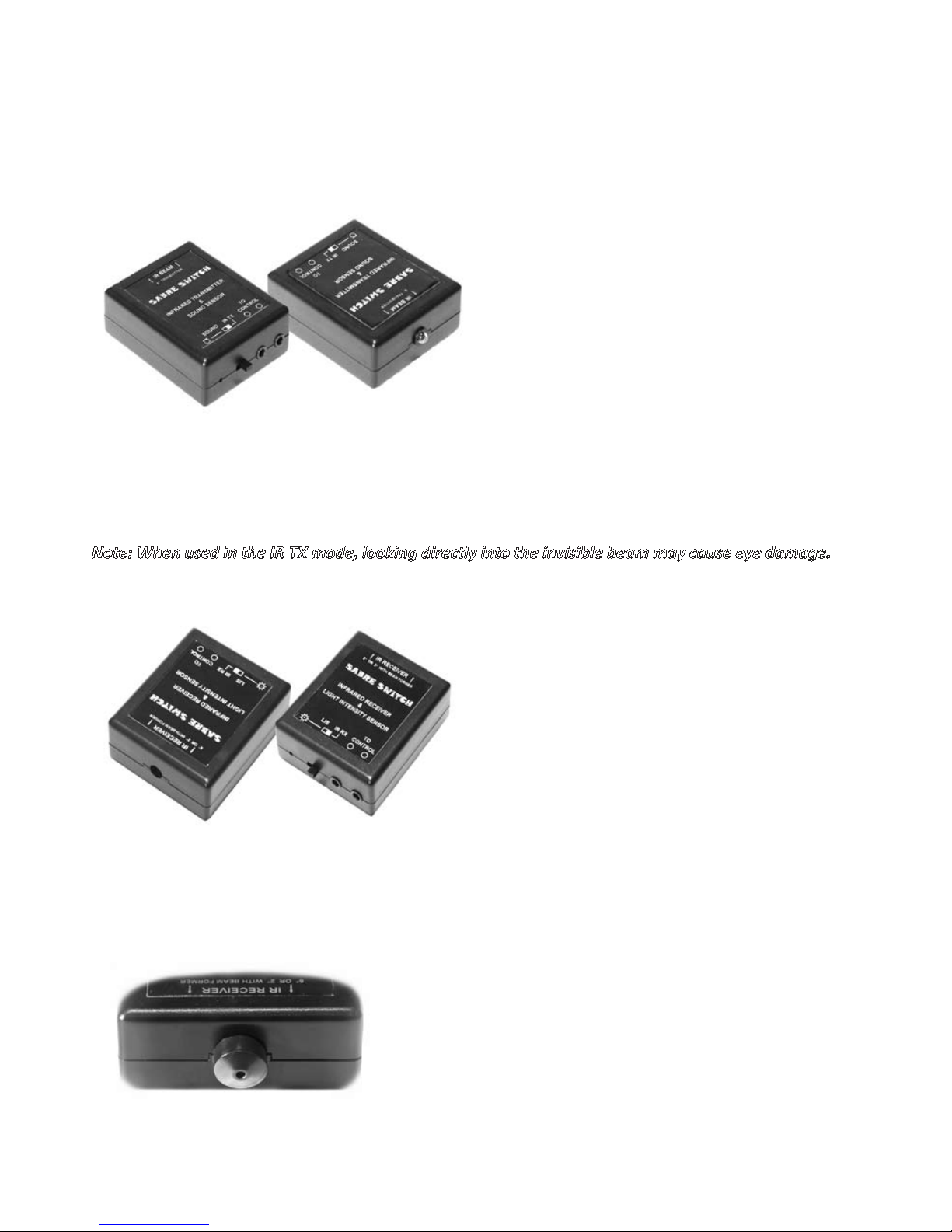
INFRARED TRANSMITTER/SOUND SENSOR MODULE
Ontherearoftheunitaswitchisprovidedto
selecttheINFRAREDorSOUNDmodesandtwo
3.5mmjacksocketstoconnecttothecontrol
unit(orinthecaseofinfraredoperaon,tothe
otherunit).
WhenINFRAREDTRANSMITTER(IRTX)is
selected,theunitsendsaninvisiblebeamto
bedetectedbythesecondunit,theINFRARED
RECEIVER(IRRX).Thebeamisnomorethan60
wideandsothetwounitsmustbealignedquiteaccurately.
WhentheswitchissettoSOUND,theunitulisesitsintegralsensivemicrophonetotransmit
asignaltotheMAINCONTROLUNIT.
Note: When used in the IR TX mode, looking directly into the invisible beam may cause eye damage.
INFRARED RECEIVER/LIS MODULE
InasimilarwaytotheIRTX/SOUNDunit,this
modulehasarearpanelcontainingaswitchto
selectLIGHTINTENSITYSENSOR(LIS)orINFRA-
REDRECEIVER(IRRX).Italsohastwo3.5mm
jacksocketstoconnectinasimilarwaytothat
ofthepreviousunit.
WhenthisunitissettoLISitispossibleto
detectsuddenincreasesinlightintensity,such
aslightning.Thisisdependentontheamount
ofambientlightandwillbefoundtobemost
accurateinlowlightordarksituaons.
WhentheswitchisselectedtousetheINFRAREDSENSOR(IRRX)funcon,themoduleneeds
tobealignedaccuratelywiththeIRTXunitwithinthe60angle.Whenalignedcorrectlythe
beamwillmakethecircuitandwhenbrokentheunittriggerstheMAINCONTROLUNIT.
Ifverysmallobjectsneedtobedetected,a20 baeis
supplied.ThiscanbeaachedtothefrontoftheIRRX
moduleandrestrictstheangleofthereceivedbeamto
only20.Therefore,greataccuracyandsensivitycanbe
achievedwhencapturingsmallobjects.
20 baeinplace
8

CONNECTING THE SYSTEM – SAMPLE SETUP
Note: Beforeconnecnganyequipmentofanykindensurethateachitemiscompablewiththe
MCT-1unitandthecamera.NoliabilitywillbeacceptedbytheCompanyforanydamageorloss
resultingfromtheconneconofincompableorfaultyequipment.
Note: Beforeconnecngordisconnecnganyitemensurethatallunitsareswitchedo.
Note: Ensurethatallequipmentisadequatelyprotectedfromtheingressofliquidsortheeectsof
excessivehighorlowtemperatures.
SAMPLE SCENARIO 1 – SOUND DETECTION
Forthisscenariothefollowingequipmentisused:-
1. Yourcameraofchoice(ensuringcompability)
2. Cameratripod(asrequired)
3. TheMCT-1ControlUnit
4. TheINFRAREDTRANSMITTER/SOUNDSENSORUNIT
5. A3.5mmjackto3.5mmjackcable
6. A2.5mmjackto2.5mmjackcameratriggercable
Method
1.BeforeswitchingonthepowerswitchoftheMCT-1andhavinginsertedthe
baeriescorrectlyintothecontrolunit(and/orulisinganMP-1),operatetheMODE
switchontherearpaneloftheMCT-1shownasLIS/SOUNDORI.REDtothele,to
selectLIS/SOUND.
2.OperatetheswitchontherearpaneloftheINFRAREDTRANSMITTER/SOUND
SENSORUNITfromIRTXtoSOUND.
Sound/LISconnecons
9

3.ConnecttheINFRAREDTRANSMITTER/SOUNDSENSORUNITbyinserngthe
3.5mmjackintoonesocketontherearofthisunit,indicatedasTOCONTROL,to
themainMCT-1controlunitbyinserngtheotherendofthe3.5mmjackcableinto
eitherofthesocketsontherearoftheMCT-1markedTOSENSORS1or2.
4.Withthecameraswitchedo,connectthecameratotheMCT-1usingthe
2.5mmjackcableinsertedintothesocketontherearpaneloftheMCT-1unitmarked
TRIGGEROUT–CAMERAandtothe2.5mmremotecontrolsocketonthecameraof
choice.
5.SwitchonthepowertotheMCT-1unitwiththePOWERON/OFFswitch
ontherearoftheMCT-1unit.
6.PlacetheINFRAREDTRANSMITTER/SOUNDSENSORUNITclosetothesubject
onthetablesurfaceforbesteffectandadjusttheSENSITIVITY,increasingthe
levelunltheorangeLEDilluminates.WhentheLEDilluminatesturnthecontrol
an-clockwiseunltheLEDjustexnguishes.Thisistheopmumposion.Ifthe
controlissettoohighthenfalsetriggeringmayoccur.
7.SettheRESET–AUTO/MANUALswitchtotherequiredposion.
8.SettheTRIGGERDELAYfullytoan-clockwiseandtheTRIGGERDELAY
switchtoSHORT(REDLED).
9.SettheTRIGGERTIMEcontrolfullyan-clockwise.
10.SwitchtheTRIGGERTIME–AUTO/MANUALswitchtoAUTO(GREEN
LED).
11.Focusthecamera,eitherviatheFOCUSswitchontheMCT-1orbyway
ofthecameracontrols.Itmaybefoundthatswitchingthecameralensto
manualfocusallowsthecameratotriggeratafasterreaconmeas
focusingisnolongernecessary.
12.Considertheneedforextralighngtoilluminatethesubjectcorrectly
forthedesiredeect.
13.Setthecameratotherequiredsengsinrespectofshuerspeed,
aperture,etc,havingregardtodepthofeldandtheamountofmovement
tobeallowedintheshot.
14.SettheSENSITIVITY-ACTIVE/INHIBITswitchtoACTIVE(GREENLED).
Thecamerawillnowbetriggeredatthenextdetecon.
10

15.Dropanobjectontothetableinthecamera’sviewareaandthesound
oftheimpactwilltriggerthecamera.Themicrophoneissensiveenough
tocapturethesoundofquitesmallobjectsbutextraneousnoisemustbe
kepttoaminimum.
16.Trialanderrorinthesengsusedinrespectofthecamera,shuer
speed,aperture,lighng,triggerdelay,etc,willenabletheoperatortond
theopmumsengsfortheresultsrequired.(Therangeofpossiblesengs
conguraonsisalmostendlesswhencombinedwiththoseofthecamera.)
Bytrialanderror,extremelygoodresultscanbeachievedinaveryshortspaceofme.
Note: Ifusingbreakableobjects,suchasglass,remembertowearthenecessarysafetyequipment
orprotectyourselffrominjury.
SAMPLE SCENARIO 2 – LIGHT DETECTION
Forthisscenariothefollowingequipmentisused:-
1. Yourcameraofchoice(ensuringcompability)
2. Cameratripod(asrequired)
3. TheMCT-1ControlUnit
4. TheINFRAREDRECEIVER/LIGHTINTENSITYSENSORUNIT
5. A3.5mmjackto3.5mmjackcable
6. A2.5mmjackto2.5mmjackcameratriggercable
7. Sensorunittripod(asrequired)
Method
1.HavinginsertedthebaeriescorrectlyintotheMCT-1controlunit(and/or
ulisinganMP-1),operatetheMODEswitchontherearpaneloftheMCT-1shownas
LIS/SOUNDORI.REDtothele,toselectLIS/SOUND.
2.OperatetheswitchontherearpaneloftheINFRAREDRECEIVER/LIGHT
INTENSITYSENSORUNITfromIRRXtoLIS.
3.ConnecttheINFRAREDRECEIVER/LIGHTINTENSITYSENSORUNITbyinserng
the3.5mmjackintoonesocketontherearofthisunit,indicatedasTOCONTROL,to
themainMCT-1controlunitbyinserngtheotherendofthe3.5mmjackcableinto
eitherofthesocketsontherearoftheMCT-1markedTOSENSORS1or2.
4.ConnectthecameratotheMCT-1usingthe2.5mmjackcableinsertedintothe
socketontherearpaneloftheMCT-1unitmarkedTRIGGEROUT–CAMERAandto
the2.5mmremotecontrolsocketonthecameraofchoice.
11

5.SwitchonthepowertotheMCT-1unitwiththePOWERON/OFFswitchonthe
rearoftheMCT-1unit.
6.PlacetheINFRAREDRECEIVER/LIGHTINTENSITYSENSORUNITfacingtowards
theexpectedlightsource.AdjusttheSENSITIVITY,increasingthesensivityunlthe
orangeLEDilluminates.WhentheLEDilluminatesturnthecontrolan-clockwiseunl
theLEDjustexnguishes.Thisistheopmumposion.Ifthecontrolissettoohigh
thenfalsetriggeringmayoccur.
7.SettheRESET–AUTO/MANUALswitchtotherequiredposion.
8.SettheTRIGGERDELAYfullytoan-clockwiseandtheTRIGGERDELAYswitchto
SHORT(REDLED).
9.SettheTRIGGERTIMEcontrolfullyan-clockwise.
10.SwitchtheTRIGGERTIME–AUTO/MANUALswitchtoAUTO(GREENLED).
11.Focusthecamera,eitherviatheFOCUSswitchontheMCT-1orbywayofthe
cameracontrols.Itmaybefoundthatswitchingthecameralenstomanualfocus
allowsthecameratotriggeratafasterreaconmeasautomacfocusingisno
longernecessary.
12.Setthecameratotherequiredsengsinrespectofshuerspeed,aperture,etc,
havingregardtodepthofeldandtheamountofmovementtobeallowedinthe
shot.
13.Considerlockingthecameramirrorintheupposion,ifpossible,asthiscuts
downevenfurtherthereaconmeofthecamera.
14.SettheSENSITIVITY-ACTIVE/INHIBITswitchtoACTIVE(GREENLED).Thecamera
willnowbetriggeredatthenextdeteconoflight.
15.Trialanderrorinthesengsusedinrespectofthecamera,shuerspeed,
aperture,lighng,triggerdelay,etc,willenabletheoperatortondtheopmumset
ngsfortheresultsrequired.(Therangeofpossiblesengsconguraonsisalmost
endlesswhencombinedwiththoseofthecamera.)
12

SAMPLE SCENARIO 3 – INFRARED BEAM
Forthisscenariothefollowingequipmentisused:-
1. Yourcameraofchoice(ensuringcompability)
2. Cameratripod(asrequired)
3. TheMCT-1ControlUnit
4. TheINFRAREDTRANSMITTER/SOUNDSENSORUNIT
5. TheINFRAREDRECEIVER/LIGHTINTENSITYSENSORUNIT
6. x23.5mmjackto3.5mmjackcable
7. A2.5mmjackto2.5mmjackcameratriggercable
8. x2minitripods
9. The20beambaesupplied
Method
1.HavinginsertedthebaeriescorrectlyintotheMCT-1controlunit(and/or
ulisinganMP-1),operatetheMODEswitchontherearpaneloftheMCT-1shown
asLIS/SOUNDORI.REDtotheright,toselectI.RED.
2.OperatetheswitchontherearpaneloftheINFRAREDTRANSMITTER/SOUND
SENSORUNITfromSOUNDtoIRTX.
3.OperatetheswitchontherearpaneloftheINFRAREDRECEIVER/LIGHT
INTENSITYSENSORUNITfromLIStoIRRX.
4.ConnecttheINFRAREDTRANSMITTER/SOUNDSENSORUNITbyinserngthe
3.5mmjackintoonesocketontherearofthisunit,indicatedasTOCONTROL,to
themainMCT-1controlunitbyinserngtheotherendofthe3.5mmjackcableinto
eitherofthesocketsontherearoftheMCT-1markedTOSENSORS1or2.
5.ConnecttheINFRAREDRECEIVER/LIGHTINTENSITYSENSORUNITbyinserng
the3.5mmjackintoonesocketontherearofthisunit,indicatedasTOCONTROL,
tothemainMCT-1controlunitbyinserngtheotherendofthe3.5mmjack
cableintooneoftheothersocketsontherearoftheMCT-1,markedTOSENSORS1
13
Infraredparallelconnecons Infrareddaisy-chainconnecons

or2,OR‘daisy-chain’thetwosensorunitstogetherbypluggingthe3.5mmjackinto
theothersocketontherearoftheINFRAREDTRANSMITTER/SOUNDSENSORUNIT
indicatedasTOCONTROL.Seeabovediagram.
6.ConnectthecameratotheMCT-1usingthe2.5mmjackcableinsertedintothe
socketontherearpaneloftheMCT-1unitmarkedTRIGGEROUT–CAMERAandto
the2.5mmremotecontrolsocketonthecameraofyourchoice.
7.CarefullyalignthebeamlensonthefrontoftheINFRAREDTRANSMITTER/
SOUNDSENSORUNITwiththereceiverapertureonthefrontoftheINFRARED
RECEIVER/LIGHTINTENSITYSENSORUNIT.Thismustbewithinanangleof60tothe
beamlens.(Ifanarrower,moreaccurate,beamisrequiredthenthe20beam
baesuppliedshouldbeclickedintotheapertureonthefrontofthereceiverunit).
8.Thedistancebetweentheunitscanbebetween30cmand2m).
9.SwitchonthepowertotheMCT-1unitwiththePOWERON/OFFswitchonthe
rearoftheMCT-1unit.
Note:WhenusedintheIRTXmode,lookingintotheinvisiblebeammaycausepermanenteyedamage.
10.AdjusttheSENSITIVITY,byincreasingthesensivityunltheorangeLED
illuminates.WhentheLEDilluminatesturnthecontrolan-clockwiseunltheLED
justexnguishes.Thisistheopmumposion.Ifthecontrolissettoohighthenfalse
triggeringmayoccur.(Ifusedoutside,brightsituaonsmayconfusethesensor.Never
directthesensorinthedireconofthesunasitcouldbesaturatedbyIRfromthe
sunsrays.)
11.SettheRESET–AUTO/MANUALswitchtotherequiredposion.
12.SettheTRIGGERDELAYfullytoan-clockwiseandtheTRIGGERDELAYswitchto
SHORT(REDLED).
13.SettheTRIGGERTIMEcontrolfullyan-clockwise.
14.SwitchtheTRIGGERTIME–AUTO/MANUALswitchtoAUTO(GREENLED).
15.Focusthecamera,eitherviatheFOCUSswitchontheMCT-1orbywayofthe
cameracontrols.Itmaybefoundthatswitchingthecameralenstomanualfocus
allowsthecameratotriggeratafasterreaconmeasfocusingisnolonger
necessary.
16.Considertheneedforextralighngtoilluminatethesubjectcorrectlyforthe
desiredeect.
14

17.Setthecameratotherequiredsengsinrespectofshuerspeed,aperture,etc,
havingregardtodepthofeldandtheamountofmovementtobeallowedinthe
shot.
18.Considerlockingthecameramirrorinthe‘UP’posion,ifpossible,asthiscuts
downevenfurtherthereaconmeofthecamera.
19.SettheSENSITIVITY-ACTIVE/INHIBITswitchtoACTIVE(GREENLED).Thecamera
willnowbetriggeredatthenextdeteconofanobjectpassingthroughthebeam.
20.Trialanderrorinthesengsusedinrespectofthecamera,shuerspeed,
aperture,lighng,triggerdelay,etc,willenabletheoperatortondtheopmum
sengsfortheresultsrequired.(Therangeofpossiblesengsconguraonsis
almostendlesswhencombinedwiththoseofthecamera.)
21.Consideraonshouldalsobegiventothedistancebetweenthebeamandthe
camera.Forinstance,anobjectdroppingthroughthebeamwillhaveanitetravelling
mebeforeitreachesthepointatwhichitentersthecamera’sview.Itmaybe
advantageoustoincreasethedistancebetweenthebeamdeteconandthecamera
andthenulisethetriggerdelaytoadjustthepointatwhichthecameraactuates.
Severalaemptscouldproduceame/distancetypecharttoopmisesuccessrates.
SAMPLE SCENARIO 4 – MANUAL TRIGGER
ThecameramayberemotelyoperatedbypressingtheTRIGGERbuondespiteanyofthe
othersengsmadeontheMCT-1.ConnuedoperaonoftheTRIGGERbuonwiththecamera
settomulpleexposuresengswillcausethecameratoshootconnuallyunlpressureon
thebuonisreleased.
SAMPLE SCENARIO 5 – AUXILIARY OUTPUT
TwocamerasmaybeconnecteddirectlytotheMCT-1viathetriggeroutsockets.However,it
mustberememberedthatthecamerapre-focusingfacilityONLYappliestotheoutputmarked
asCAMERA.TheoutputconneconmarkedAUX.,willacvatethecamerashuerbutnotthe
focus.Therefore,thesecondcameramustbemanuallyfocused.
ThesecondTRIGGEROUTcircuitcanalsobeusedtooperateavarietyofaddionalequipment.
Thiscouldincludeaslaveoranaddionalashgun.However,onlyoneitemofaddional
equipmentshouldbeconnectedatanyoneme.
15
Auxiliaryconnecons

SPECIFICATIONS
TRIGGERTIME -Selectablefor-5ms(1/200sec.)to-5seconds
DELAYTIME -Shortdelay-1ms(1/1000sec.)to100ms(1/10sec.).
-Longdelay-1000ms(1/10sec.)to10seconds.
TRIGGERMODES-Manual,auto1shot,autore-arm.
FOCUSACTIVATION-Manualacvaon.
SENSORMODES -Flash,infraredbeam,sound.
IRBEAM-Range-20cmto-2m.Wavelength850nm.
FLASHSENSOR -Range1to1500lumens.Sensivity10lumens.
SOUNDRESPONSE-Microphonesensivity-frequencyresponse50to5000Hzat
3Db.
TRIGGEROUTPUTS-x3opencollector(x2trigger,x1focus).50vDCmaxat
100milliamps.
POWERREQUIREMENTS-x4AAbaeries,highpowertype,non-rechargeable.
-ACtolowvoltagePSU-6to9VDCat100milliamps.Unittobe
doubleinsulated.(Usedisconnectsinternalbaeries.)
POWERCONSUMPTION-About40milliamps.
WhenIRTXmoduleisconnectedrisesto80milliamps.
SIZE -Controller-(W)19cmx(D)14cmx(H)5cm.
-Sensors(W)7.5cmx(D)5cmx(H)2.6cm.
SENSORMOUNTING-¼inchUNCthread(standardtripodthread).
MINITRIPODHEIGHT-8cmmin.17cmmax.
WEIGHT-Controller492gSensors50gTripods30g.
WATERPROOFING-IP53.
TEMPERATURE -0to350C.(operang).-10to+500C.(non-operang).
SHOCK -10Newtons.
16

TRIGGER INPUT TO CAMERA
IMPORTANT SAFETY INSTRUCTIONS
Everyconsideraonhasbeentakentoensurecorrectoperaonofthisprod-
uctwithmostcameras.However,noconnecontoacameraorotherequip-
mentshouldbemadeunlesstheoperatoriscertainofthecompabilityofthe
equipment.NoliabilitycanbeacceptedbytheCompanyforanyconsequenal
faultordamagecausedtoanyequipmentnotsuppliedbytheCompany.
ThefollowingcameraswillconnectdirectlytotheMCT-1withthetriggercable
provided:-
CANON
EOS30,EOS33,EOS50E,EOS300,EOS300V,EOS300D,EOS350D,EOS3000,
EOS50,EOS500,EOS55,EOS500N,EOS300X,EOSKiss,EOSNewKiss,EOS
Kiss7,EOSKissIII,EOS7,EOS7s,EOS400D,EOSDigitalRebel,EOSDigital
RebelX,EOSDigitalRebelXSi,EOSKISSX2,EOS450D,EOSDigitalRebelXTi,
KissDigital,KissDigitalN,ELAN7N,ELANII,ELANDATE,ELAN7,ELAN7NE,
ELAN7N,ELANIIE,Rebel2000,RebelG,RebelT2,RebelTi,RebelX,RebelXS,
EOS1000D,EOS500D,RebelT1i,
EOS550D,RebelT2i,G10,G11,G12,60D,600D,RebelT3i,KissX5,1100D,
RebelT3
PENTAX
K100D,K110D,K10D,*istDS2,K200D,K20DK7,*istD,*istDS,*ist,*istDL,
MZ-6,ZX-L,MZ-,*ist,DL2,K5
SAMSUNG
GX-1L,GX-1S,GX-10,GX-20,NX10,NX100,NX5
CONTAX
645,N,N1,NX,NDigital
Othercameraswillrequireanadapter.Typically,thefollowingmanufacturersmay
oeradapters:-
Calumet
JJCCorporaon
HahnelEire
HAMA
Alloftheabovewillrequirea2.5mmfemaleto3.5mmmaleorfemale3pole
adapter.

PRODUCT WARRANTY
THEMANUFACTURERwarrantsfor12monthstotheoriginalpurchaserthatTHEMANUFACTURER’S
productsarefreefromdefectsinmaterialandworkmanshipundernormaluseandservice
fortheperiodspeciedcommencinguponthedateofpurchasefromanauthoriseddealer.
ThisLimitedWarrantyiscondionaluponproperuseoftheproductbythepurchaser.
ThisLimitedWarrantydoesnotcover:(a)defectsordamageresulngfromaccident,misuse,
abuse,neglect,unusualphysicalorelectricalstress,modicaonofanypartoftheproduct,
orcosmecdamage;(b)equipmentthathasaserialnumberremovedormadeillegible;(c)
allplascsurfacesandotherexternallyexposedpartsthatarescratchedordamageddueto
normaluse;(d)defectsordamagefromimpropertesng,operaon,maintenance,installaon,
adjustment,orserviceoftheproducts.
Duringtheapplicablewarrantyperiod,THEMANUFACTURERwillrepairorreplace,atTHE
MANUFACTURER’Ssolediscreonwithoutchargetothepurchaser,anydefecvecomponent
partoftheproduct.THEMANUFACTURERmay,atTHEMANUFACTURER’Ssolediscreon,
userebuilt,recondioned,ornewpartsorcomponentswhenrepairinganyproductor
replaceaproductwitharebuilt,recondionedornewproduct.
THEWARRANTIESGIVENINTHISLIMITEDWARRANTY,TOGETHERWITHANYIMPLIEDWARRANTIES
COVERINGTHEMANUFACTURER’SPRODUCTS,INCLUDINGWITHOUTLIMITATIONANYWARRANTIES
OFMERCHANTABILITYORFITNESSFORAPARTICULARPURPOSE,ARELIMITEDTOTHE
DURATIONOFTHISLIMITEDWARRANTY.
THEMANUFACTURERSHALLNOTBELIABLEFORANYSPECIALINCIDENTAL,CONSEQUENTIAL,
INDIRECTORSIMILARDAMAGES,DAMAGESTOPURCHASER’SPROPERTY,ORINJURYTOTHE
PURCHASEROROTHERSARISINGOUTOFTHEUSE,MISUSEORINABILITYTOUSEANYOFTHE
MANUFACTURER’SPRODUCTS,BREACHOFWARRANTY,ORNEGLIGENCE,INCLUDINGBUT
NOTLIMITEDTOTHEMANUFACTURER’SOWNNEGLIGENCE,EVENIFTHEMANUFACTUREROR
IT’SAGENTHASBEENADVISEDOFSUCHDAMAGES,ORFORANYCLAIMBROUGHTAGAINST
THEPURCHASERBYANYOTHERPARTY.
THISLIMITEDWARRANTYISTHECOMPLETEWARRANTYFORTHEMANUFACTURER’SPRODUCTS.
THISLIMITEDWARRANTYSHALLNOTEXTENDTOANYONEOTHERTHANTHEORIGINAL
PURCHASEROFTHISPRODUCT.
FOR TRANSLATION OF THIS INSTRUCTION MANUAL VISIT:
www.sabreswitch/translate.co.uk
Made in the UK by Sabre Switch
WorldwidedistribuonbyFlagheadPhotographicLimited
POBox6143,Poole,Dorset.BH129AS
Tel:044(0)1202733123Fax:044(0)1202737428
Email:info@aghead.co.ukWeb:www.aghead.co.uk
www.sabreswitch.co.uk
145-90 V7.0 2/12
FLAGHEAD
Photographic
Table of contents