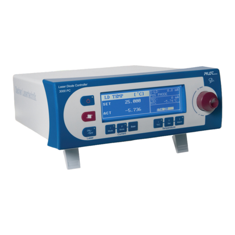
Sacher Lasertechnik LB2001 User manual

Operation Manual LB2001
Sacher Lasertechnik
GmbH
_____________________________________________________________________________________________________
Adress:
Sacher Lasertechnik GmbH
Rudolf-Breitscheid-Str. 1-5
D-35037 Marburg, Germany
Tel.: +49 (6421) 305-0
Fax.: +49 (6421) 305-299
EMail: contact@sacher-laser.com
Web: http://www.sacher-laser.com
Sacher Lasertechnik, LLC
5765 Equador Way
Buena Park, CA 90620, USA
Tel.: 1-714-670-7605
Fax: 1-714-670-7662
Email: sales@sacher-
laser.com
Page 1
Version:
Preliminary 2011-01-01
Operating Manual
Servo Controller LB2001

Operation Manual LB2001
Sacher Lasertechnik
GmbH
_____________________________________________________________________________________________________
Adress:
Sacher Lasertechnik GmbH
Rudolf-Breitscheid-Str. 1-5
D-35037 Marburg, Germany
Tel.: +49 (6421) 305-0
Fax.: +49 (6421) 305-299
EMail: contact@sacher-laser.com
Web: http://www.sacher-laser.com
Sacher Lasertechnik, LLC
5765 Equador Way
Buena Park, CA 90620, USA
Tel.: 1-714-670-7605
Fax: 1-714-670-7662
Email: sales@sacher-
laser.com
Page 2
Version:
Preliminary 2011-01-01
1.Basic Safety Instructions
The LB2001 is a versatile instrument that can be used in a variety of feedback control
applications. However, the LB2001 is not intended for fail-safe operation in hazardous
environments or life-threatening situations. The user assumes full responsibility for correct
and safe usage of the LB2001 in accordance with any applicable laws, codes, regulations, and
standards pertaining to their specific application. Sacher Lasertechnik is not liable for any
consequential damage due to misapplication or failure of the LB2001.
Electrical Fuse & Voltage Selection
The LB2001 is pre-configured at the factory to work with the AC mains voltages for your
region. Before supplying electrical power to the LB2001, confirm that the power entry
module located on the rear panel is installed with the proper fuses and set to the correct wall-
plug AC voltage.
AC Mains*
V~ Tolerance
V~ Fuse Rating**
Module Voltage
Switch Settings
115 90-120 250V
0.5 A T 230
230 207-264 250V
0.25 A 115
*50/60 Hz only. ** Module accept only dual metric 5 x 20 mm fuses.
To operate at another AC mains voltage, follow the procedure below:
• With a small screwdriver, pry open fuse cover of the power entry module on rear
panel. The AC power cord must be removed from module socket before opening fuse cover.
• Carefully pull out the voltage selection wheel from the module. Re-insert so that
correct AC voltage setting is facing outwards.
• Pull out the two fuse holders located below voltage selection wheel. Insert correct
fuses into each fuse holder and re-insert back into module. Install fuse holders so that arrows
on fuse cover and fuse holder align.
• Snap fuse cover back into place. Verify that the correct AC mains voltage can be read
through fuse panel before attaching the AC power cord.
Warning: Carefully measure output voltages from the LB2001 before connecting to a
device that can be damaged by over-voltage.

Operation Manual LB2001
Sacher Lasertechnik
GmbH
_____________________________________________________________________________________________________
Adress:
Sacher Lasertechnik GmbH
Rudolf-Breitscheid-Str. 1-5
D-35037 Marburg, Germany
Tel.: +49 (6421) 305-0
Fax.: +49 (6421) 305-299
EMail: contact@sacher-laser.com
Web: http://www.sacher-laser.com
Sacher Lasertechnik, LLC
5765 Equador Way
Buena Park, CA 90620, USA
Tel.: 1-714-670-7605
Fax: 1-714-670-7662
Email: sales@sacher-
laser.com
Page 3
Version:
Preliminary 2011-01-01
Table of Symbols
Alternating current
Caution – risk of electrical shock
Fuse
It is well known that WEEE pollutes the environment by
releasing toxic products during decomposition. The aim of the
European RoHS directive is to reduce the content of toxic
substances in electronic products in the future.
The intent of the WEEE directive is to enforce the recycling of
WEEE. A controlled recycling of end of life products will
thereby avoid negative impacts on the
environment.

Operation Manual LB2001
Sacher Lasertechnik
GmbH
_____________________________________________________________________________________________________
Adress:
Sacher Lasertechnik GmbH
Rudolf-Breitscheid-Str. 1-5
D-35037 Marburg, Germany
Tel.: +49 (6421) 305-0
Fax.: +49 (6421) 305-299
EMail: contact@sacher-laser.com
Web: http://www.sacher-laser.com
Sacher Lasertechnik, LLC
5765 Equador Way
Buena Park, CA 90620, USA
Tel.: 1-714-670-7605
Fax: 1-714-670-7662
Email: sales@sacher-
laser.com
Page 4
Version:
Preliminary 2011-01-01
2.Customer Support
Information and advice about the performance or operation of Sacher Lasertechnik
Group
products is available from our web site and our applications engineers.
For quickest response ask for ‘Technical Support’ and have your model and serial number
available. Support is available by:
Sacher Lasertechnik
Group
Rudolf-Breitscheid-Str. 1-5
35037 Marburg, Germany
Tel: +49 6421 305 – 0, Fax: +49 6421 305 - 299
Contact@sacher-laser.com
or
5765 Equador Way
Buena Park, CA 90620
USA
The LB2001 is designed to be maintenance free. No user-serviceable parts are
inside the unit. No further calibrations are necessary for the LB2001 to meet its
accuracy specifications over the lifetime of the product. Opening the instrument
case voids the warranty and exposes to user to hazardous voltages that are
present inside the instrument case.
Cleaning instructions: Instrument case can be safely cleaned with slightly
moistened cloth soaked in water or isopropyl alcohol.

Operation Manual LB2001
Sacher Lasertechnik
GmbH
_____________________________________________________________________________________________________
Adress:
Sacher Lasertechnik GmbH
Rudolf-Breitscheid-Str. 1-5
D-35037 Marburg, Germany
Tel.: +49 (6421) 305-0
Fax.: +49 (6421) 305-299
EMail: contact@sacher-laser.com
Web: http://www.sacher-laser.com
Sacher Lasertechnik, LLC
5765 Equador Way
Buena Park, CA 90620, USA
Tel.: 1-714-670-7605
Fax: 1-714-670-7662
Email: sales@sacher-
laser.com
Page 5
Version:
Preliminary 2011-01-01
For service or repairs:
Tel.: +1 800 352 3639, Fax: +1 714 670 7662
1. Telephone Sacher Lasertechnik customer service department at (+49) 6421 305290,
which will determine if the equipment requires service, repair, calibration, or replacement.
Factory office hours are 8:00 am-4:00 pm CET.
2. If the unit must be returned to Sacher Lasertechnik, ask for a Return Merchandise
Authorization (RMA) from customer service. Never send any unit back to Sacher
Lasertechnik without a Return Merchandise Authorization (RMA).
3. Return the unit, postage prepaid, to Sacher Lasertechnik. Do not forget to write the
RMA on the shipping label. Sacher Lasertechnik will refuse and return any package that does
not bear an RMA.
4. Pack the unit in its original shipping material (if possible) with at least 1 inch of
compressible packing material. Be sure to include an ownership tag and a description fully
detailing the defect and the conditions under which it was observed.
5. After repair, the equipment will be returned with a repair report. If the equipment was
within specifications, a test set-up fee will be charged to the customer. If the equipment is not
under warranty, the customer will be invoiced for the cost appearing on the repair report.
6. Sacher Lasertechnik is responsible for shipping the unit back to the customer if the
unit is under warranty. Shipping damage is not covered by this warranty, and shipping
insurance, which Sacher Lasertechnik recommends, is at the customer’s expense.

Operation Manual LB2001
Sacher Lasertechnik
GmbH
_____________________________________________________________________________________________________
Adress:
Sacher Lasertechnik GmbH
Rudolf-Breitscheid-Str. 1-5
D-35037 Marburg, Germany
Tel.: +49 (6421) 305-0
Fax.: +49 (6421) 305-299
EMail: contact@sacher-laser.com
Web: http://www.sacher-laser.com
Sacher Lasertechnik, LLC
5765 Equador Way
Buena Park, CA 90620, USA
Tel.: 1-714-670-7605
Fax: 1-714-670-7662
Email: sales@sacher-
laser.com
Page 6
Version:
Preliminary 2011-01-01
Warranty
Sacher Lasertechnik GmbH warrants its LB2001 to be free of material and workmanship
defects for one year from the date of original shipment. This warranty is in lieu of all other
guarantees expressed or implied, including any implied warranty of merchantability or fitness
for any particular purpose. Sacher Lasertechnik shall not be liable for any special, incidental
or consequential loss.
During the warranty period, Sacher Lasertechnik will repair or replace the unit, or issue credit,
at our option, without charge. Sacher Lasertechnik’ liability shall not in any case exceed the
cost of correcting defects in the products as explained here, and this service is the sole
remedy of the buyer.
This warranty does not apply to defects caused by abuse, accident, modifications,
Acts of God, or to use of the product for which it was not intended.
Sacher Lasertechnik shall not be liable for damages resulting from the use of the
product, nor shall be responsible for any failure in the performance of other items to
which the purchased product is connected or the operation of any system of which
the purchased product may be a part. The LB2001 should not be used in a manner
not specified by the manufacturer.

Operation Manual LB2001
Sacher Lasertechnik
GmbH
_____________________________________________________________________________________________________
Adress:
Sacher Lasertechnik GmbH
Rudolf-Breitscheid-Str. 1-5
D-35037 Marburg, Germany
Tel.: +49 (6421) 305-0
Fax.: +49 (6421) 305-299
EMail: contact@sacher-laser.com
Web: http://www.sacher-laser.com
Sacher Lasertechnik, LLC
5765 Equador Way
Buena Park, CA 90620, USA
Tel.: 1-714-670-7605
Fax: 1-714-670-7662
Email: sales@sacher-
laser.com
Page 7
Version:
Preliminary 2011-01-01
3.Prepare for Use
This chapter gives an overview of the front panel controls and connectors of the LB2005
servo controller and gives all information that is necessary to put the instrument into operation
and connect external devices.
3.1. Frontpanel Tour
The front panel of the LB2005 consists of the 7 segment displays hardkeys and the
incremental rotation encoders.. Brief explanations on the controls rear panel can be found on
the next pages
1
2
3
4
5
6
7
8
9
A
B
C
D
E
F
G
H
I
J
K

Operation Manual LB2001
Sacher Lasertechnik
GmbH
_____________________________________________________________________________________________________
Adress:
Sacher Lasertechnik GmbH
Rudolf-Breitscheid-Str. 1-5
D-35037 Marburg, Germany
Tel.: +49 (6421) 305-0
Fax.: +49 (6421) 305-299
EMail: contact@sacher-laser.com
Web: http://www.sacher-laser.com
Sacher Lasertechnik, LLC
5765 Equador Way
Buena Park, CA 90620, USA
Tel.: 1-714-670-7605
Fax: 1-714-670-7662
Email: sales@sacher-
laser.com
Page 8
Version:
Preliminary 2011-01-01
1
2
3
6
7
8
9
A
5
4
The detailed functions are:
Bias voltage level. The position of the LED signal indicates the position of the bias
voltage level relative to the +/-10V operation range of the LB2001
Save Switch remote indicator. When “Save” is pressed all settings will be stored in a
EEPROM
Unit indicator for PI Corner frequency
Acquire Buttons: These buttons are used to acquire lock. Table 2 shows
the function for each switch position.
The position of the Green LED signal indicates the position of the integrator level
relative to the +/-10V operation range of the LB2001.
The position of the Red LED signal indicates the position of the Error level relative to
a +/-50mV voltage range. The locked system should always be in the the +/-50mV window.
Filter parameter display
Display indicators. Shows which parameter could be adjusted with the rotary switch.
Filter Frequency Adjustment: Depending on the setting of the Low Pass / High Pass
Selection Switch, this knob adjusts
The low pass filter frequency of the high pass filter path

Operation Manual LB2001
Sacher Lasertechnik
GmbH
_____________________________________________________________________________________________________
Adress:
Sacher Lasertechnik GmbH
Rudolf-Breitscheid-Str. 1-5
D-35037 Marburg, Germany
Tel.: +49 (6421) 305-0
Fax.: +49 (6421) 305-299
EMail: contact@sacher-laser.com
Web: http://www.sacher-laser.com
Sacher Lasertechnik, LLC
5765 Equador Way
Buena Park, CA 90620, USA
Tel.: 1-714-670-7605
Fax: 1-714-670-7662
Email: sales@sacher-
laser.com
Page 9
Version:
Preliminary 2011-01-01
K
B
C
D
E
F
G
H
I
J
Polarity switch for PT1 and DT1 filter unit
Corner frequency (CF) / Attenuator selection switch
Filter selection switch.
Sweep Center (Output Offset): This knob adjusts the offset voltage of the signal from
Output. The offset voltage can be adjusted from the negative voltage limit (fully
counter clockwise) to the positive voltage limit (fully clockwise). See the section
Setting Output Voltage Limits in Chapter 3 for more details on setting the output voltage
limits.
Sweep Span: This knob controls the attenuation of the Sweep In signal. Attenuation is
near linear from zero (Off, fully counter-clockwise) to unity gain (fully clockwise).
This knob is used to adjust the amplitude of the sweep input signal.
Gain: This adjustment knob controls the overall feedback gain of the loop filter from
-40 dB (fully counter clockwise) to +40 dB (fully clockwise) with a 1dB step
resolution. The gain value is displayed above.
LF Gain Limit: This switch controls the low frequency gain limit (LFGL) of the loop
filter. The value of low frequency is displayed above. This knob is only active when
the Acquire switch is in LFGL mode. See the section Filter Transfer Functions in
Chapter 3 for details.
Display section PI corner frequency (left) , Low Frequency Gain Limit (middle)
Gain (right)
P-I Corner: This switch sets the proportional-integral (P-I) corner frequency of the
filter. The corner frequency is displayed above. See the section Filter Transfer
Functions for details.
Offset Adjustment (Bias): This adjustment knob controls a stable offset voltage with a
16 bit resolution that can be added to the voltage of input signal. This offset can be
adjusted over 10 V with a resolution of <1mV. The offset voltage changes linearly
with <1mV per step. The selected offset is displayed above.

Operation Manual LB2001
Sacher Lasertechnik
GmbH
_____________________________________________________________________________________________________
Adress:
Sacher Lasertechnik GmbH
Rudolf-Breitscheid-Str. 1-5
D-35037 Marburg, Germany
Tel.: +49 (6421) 305-0
Fax.: +49 (6421) 305-299
EMail: contact@sacher-laser.com
Web: http://www.sacher-laser.com
Sacher Lasertechnik, LLC
5765 Equador Way
Buena Park, CA 90620, USA
Tel.: 1-714-670-7605
Fax: 1-714-670-7662
Email: sales@sacher-
laser.com
Page 10
Version:
Preliminary 2011-01-01
1
2
3
4
3.2. Rear Panel Tour
Input A (non inverting input), The error signal is generated from the voltage
(A – B) applied to the BNC input connector
USB Remote Interface.
Input B (inverting input), The error signal is generated from the voltage applied to the
BNC input connector
Output (LP): This low pass BNC output is the control signal from the proportional-
integral (P-I) filter, going to the filter section and summed with the sweep and
modulation signals.
1
2
3
4
5
6
7
8
9
A
B
C
D

Operation Manual LB2001
Sacher Lasertechnik
GmbH
_____________________________________________________________________________________________________
Adress:
Sacher Lasertechnik GmbH
Rudolf-Breitscheid-Str. 1-5
D-35037 Marburg, Germany
Tel.: +49 (6421) 305-0
Fax.: +49 (6421) 305-299
EMail: contact@sacher-laser.com
Web: http://www.sacher-laser.com
Sacher Lasertechnik, LLC
5765 Equador Way
Buena Park, CA 90620, USA
Tel.: 1-714-670-7605
Fax: 1-714-670-7662
Email: sales@sacher-
laser.com
Page 11
Version:
Preliminary 2011-01-01
7
8
9
A
5
6
B
C
D
Output (HP): This high pass BNC output is the control signal from the proportional-
integral (P-I) filter and going to the DT1 filter section.
Power switch: This switch is pushed up to | position to turn on AC mains power to
LB2001.
AC Line Power Voltage Selector
Power entry module: The AC power cord must be connected between this instrument
receptacle and a properly grounded mains receptacle. The LB2001 can be configured
to operate with the following AC mains voltages: 100, 120, 220, and 230-240 VAC.
Please carefully read the preceding section Electrical Fuse & Voltage Selection for
instructions on installing the proper fuses and setting the correct AC supply voltage.
PI Filter Output Voltage Limit: This trim-pots determines the integrator voltage rails.
Sweep In 2: Input signals to this BNC connectors are summed into the Output signal.
Sweep In 1: This BNC input allows a low frequency periodic sweep signal to be
added to the output of the LB2001. The input impedance is 1k and the input voltage
range is -10V.. +10V. See Sweep Center and Sweep Span controls discussed below
for more details.
Int. Hold Input: This TTL logic input switches off the error signal input to the P-I
filter and holds the integrator output voltage at its current value
Error Monitor: This BNC output connector is a voltage monitor for the error signal
generated by the input difference amplifier. The DC-coupled error monitor has unity
gain with a nominal output voltage –10V..+10V.

Operation Manual LB2001
Sacher Lasertechnik
GmbH
_____________________________________________________________________________________________________
Adress:
Sacher Lasertechnik GmbH
Rudolf-Breitscheid-Str. 1-5
D-35037 Marburg, Germany
Tel.: +49 (6421) 305-0
Fax.: +49 (6421) 305-299
EMail: contact@sacher-laser.com
Web: http://www.sacher-laser.com
Sacher Lasertechnik, LLC
5765 Equador Way
Buena Park, CA 90620, USA
Tel.: 1-714-670-7605
Fax: 1-714-670-7662
Email: sales@sacher-
laser.com
Page 12
Version:
Preliminary 2011-01-01
Content
1. Basic Safety Instructions...................................................................................... 2
2. Customer Support................................................................................................ 4
3. Prepare for Use.................................................................................................... 7
3.1. Frontpanel Tour............................................................................................. 7
3.2. Rear Panel Tour.......................................................................................... 10
4. Getting Started................................................................................................... 13
4.1. General........................................................................................................ 13
4.2. Typical Setup............................................................................................... 13
4.3. Typical Operation ........................................................................................ 15
5. System Overview ............................................................................................... 17
5.1. Signal Architecture ...................................................................................... 17
5.2. Input Section ............................................................................................... 18
5.3. PI Filter........................................................................................................ 19
5.4. Post DT1 Filter............................................................................................. 23
5.5. Post PT1 Filter............................................................................................. 26
5.6. Frequency Splitter ....................................................................................... 29
5.7. Summing Amplifier ...................................................................................... 30
6. Remote Interface................................................................................................ 31
6.1. Architecture................................................................................................. 31
6.2. Serial Port Emulation................................................................................... 32
6.3. Serial Port Commands ................................................................................ 32
6.4. LB2001 Terminal......................................................................................... 33
7. Specifications..................................................................................................... 34
7.1. Performance Specifications......................................................................... 34
7.2. Environmental Specifications ...................................................................... 35
7.3. Electrical Specifications............................................................................... 35
7.4. Dimensions.................................................................................................. 35

Operation Manual LB2001
Sacher Lasertechnik
GmbH
_____________________________________________________________________________________________________
Adress:
Sacher Lasertechnik GmbH
Rudolf-Breitscheid-Str. 1-5
D-35037 Marburg, Germany
Tel.: +49 (6421) 305-0
Fax.: +49 (6421) 305-299
EMail: contact@sacher-laser.com
Web: http://www.sacher-laser.com
Sacher Lasertechnik, LLC
5765 Equador Way
Buena Park, CA 90620, USA
Tel.: 1-714-670-7605
Fax: 1-714-670-7662
Email: sales@sacher-
laser.com
Page 13
Version:
Preliminary 2011-01-01
4.Getting Started
4.1. General
This chapter explains the typical setup and operation of the LB2001 Servo Controller. This
chapter should help less experienced users rapidly adapt the LB2001 to their specific servo
application. Keep in mind that while the LB2001 has a flexible architecture that lends itself
well to many feedback control applications, not all types of operation can be adequately
addressed in this manual. The following are general guidelines for operating the LB2001, and
some deviation from these procedures may be required to meet specific application needs.
Demanding applications will require familiarity with feedback control theory and good
characterization of all system components.
The primary function of the LB2001 is to condition an input signal from a detector and to
provide an output signal to a transducer that controls a system parameter. The output control
signal forces the system parameter to a desired value regardless of external disturbances, such
as thermal fluctuations or mechanical noise, which invariably affect the system. The
difference between the desired value and the actual value of the controlled parameter is
typically called the error signal. For instance, the parameter to be controlled might be the
intensity of a diode laser that has its optical output detected by a photodiode. The LB2001
generates an error signal from the photodiode signal and then filters this error signal to
provide a control signal that changes the injection current to the diode laser such that a stable
optical power is maintained.
4.2.
Typical Setup
The LB2001 is designed to easily integrate with other instruments and devices. This section
describes the various electrical signal connections that might be made to and from the
LB2001. Some typical signal connections between common instruments are shown in Figure
3. Pay careful attention not to exceed any damage thresholds when making connections
between instruments.
NOTE: Before powering the LB2001, make sure that the fuse and voltage settings are correct
for your region’s wallplug electrical power (see the Electrical Fuse & Voltage Selection
section of Chapter 1.)
Detector output to LB2001 input: To provide feedback, the parameter to be stabilized
must first be detected. For example, a simple photodiode might suffice for detecting
optical intensity. For instances where the laser wavelength is stabilized,
spectrometers based on atomic/molecular or interferometer resonances are needed
to detect optical wavelength shifts. The common characteristic of all detectors is that
they produce a nonzero slope that is locally monotonic around the desired lock point.
The input section of the LB2001 is a high-impedance, differential amplifier stage that
offers flexibility in interfacing to many types of detector outputs.

Operation Manual LB2001
Sacher Lasertechnik
GmbH
_____________________________________________________________________________________________________
Adress:
Sacher Lasertechnik GmbH
Rudolf-Breitscheid-Str. 1-5
D-35037 Marburg, Germany
Tel.: +49 (6421) 305-0
Fax.: +49 (6421) 305-299
EMail: contact@sacher-laser.com
Web: http://www.sacher-laser.com
Sacher Lasertechnik, LLC
5765 Equador Way
Buena Park, CA 90620, USA
Tel.: 1-714-670-7605
Fax: 1-714-670-7662
Email: sales@sacher-
laser.com
Page 14
Version:
Preliminary 2011-01-01
The A and -B inputs can be used together with differential signals to remove common-mode
noise and systematics. Single-ended signals can also be connected, as shown by connection
1a, by simply leaving the unused channel unconnected, or, as depicted by connection 1b, by
attaching a stable voltage source that generates an external set-point voltage. Alternatively,
the Input Offset knob can provide DC offset to the detector signals. To invert either
differential or single-ended signals, use the Polarity button to reverse the connections.
Function Generator (optional)
generates Sweep Signal
Y-Channel X-Channel
Monitors Error Signal
Ocilloscope (recommended)
Detector
Photo Diode
Atomic Resonance
Setpoint Generator (optional)
Precision Voltage Source
Digital to Analog Converter
Transducer / Driver (LP)
Piezoelectric Transducer
Transducer / Driver (HP)
Laser Diode Injection Current
Controlled Parameter
Optical Frequency
External Perturbations
Temperature Drift
Accoustic Noise
1a
1b
2a
2b
3
4b
4a
LB2001 Output to transducer input: To close the feedback loop, an electrically tuned
transducer is necessary for varying the controlled parameter. (2a) A piezoelectric
transducer (PZT) to which a cavity mirror is mounted can tune the wavelength of a
laser. Typically, the LP output of the LB2001 does not interface with the transducer
directly but instead provides the input to an amplifier system that conditions the
control signal to properly drive the transducer. For the PZT discussed above, the
control signal from the LB2001 Output will usually feed a high-voltage amplifier that
connects to the PZT. Be careful not to exceed any input voltage limits of the
transducer. (2b) Variation of the laser diode injection current which tunes the
wavelength of a laser. Typically, the HP output is feed to a bias-tee which provides
modulation to the laser current. Be careful not to exceed any input voltage limits of
the bias-tee.
If necessary, the Output voltage of the LB2001 can be limited by setting the Output Voltage
Limit trim pots located on the rear panel. See section Setting Output Voltage Limits in
Chapter 3 for more details.
LB2001 Error Monitor output to oscilloscope: The Error Monitor allows the user to
view the actual error signal that is being processed by the P-I filter. Since integral
feedback forces the error signal to zero voltage, the parameter that is being
controlled will assume whatever value corresponds to zero error (equal to zero volts).
Observing the Error Monitor enables the user to adjust offsets so that the locking

Operation Manual LB2001
Sacher Lasertechnik
GmbH
_____________________________________________________________________________________________________
Adress:
Sacher Lasertechnik GmbH
Rudolf-Breitscheid-Str. 1-5
D-35037 Marburg, Germany
Tel.: +49 (6421) 305-0
Fax.: +49 (6421) 305-299
EMail: contact@sacher-laser.com
Web: http://www.sacher-laser.com
Sacher Lasertechnik, LLC
5765 Equador Way
Buena Park, CA 90620, USA
Tel.: 1-714-670-7605
Fax: 1-714-670-7662
Email: sales@sacher-
laser.com
Page 15
Version:
Preliminary 2011-01-01
point corresponds to the desired value of the controlled parameter. The error signal is
also an excellent diagnostic for monitoring the lock condition and optimizing the
feedback gain. Because the time domain behavior of the error signal is so important
to understanding the feedback control, viewing the Error Monitor output on an
oscilloscope is highly recommended.
Function generator output to LB2001 Sweep In: For detector signals that are derived
from an optical resonance, it is convenient to sweep the transducer so that the optical
frequency scans over the resonance. Observing the resonance on an oscilloscope
often makes it easier to offset the error signal so that the locking point (at zero volts)
aligns with the desired optical frequency. Furthermore, sweeping the transducer
helps to locate the resonance and place the optical frequency within the locking
range of the servo system. To add sweep capability, connect a low-frequency (30—
60 Hz is usually sufficient) triangle waveform from a function generator to the Sweep
In connector, as shown by connection 4a. The sweep signal will then be output to the
transducer, with its amplitude controlled by the Sweep Span knob. To synchronize
the sweep with the Error Monitor signal, also connect the function generator output to
the oscilloscope’s timebase trigger
4.3.
Typical Operation
The controls of the LB2001 are conveniently arranged for acquiring and optimizing lock. In
this section, five steps are suggested that will meet the needs of most applications. Figure 5
shows the controls that are most likely to be adjusted for each step. The solid lines indicate
controls that are used most often, while the dashed lines show controls that are less frequently
adjusted.
Reset integrator: Before locking, reset the integrator by moving the Acquire switch to the
Lock Off position.
Find the locking point: Many applications will require the user to search for the locking
point, such as the side or center of an optical resonance. Turn on sweeping by clicking the
Sweep Span knob from its Off position, adjusting it for a wide span. Use the Sweep
Center knob to adjust the transducer bias so that the lock feature is “centered” within the
scan. If needed, the desired lock point can be adjusted to zero voltage with the Input Offset
knob while monitoring the error signal. Adjust both the Sweep Center and Sweep Span
controls so that the oscilloscope scan shows the discriminator slope of the lock feature. Figure
4 illustrates these concepts for a “side lock” to a resonance.

Operation Manual LB2001
Sacher Lasertechnik
GmbH
_____________________________________________________________________________________________________
Adress:
Sacher Lasertechnik GmbH
Rudolf-Breitscheid-Str. 1-5
D-35037 Marburg, Germany
Tel.: +49 (6421) 305-0
Fax.: +49 (6421) 305-299
EMail: contact@sacher-laser.com
Web: http://www.sacher-laser.com
Sacher Lasertechnik, LLC
5765 Equador Way
Buena Park, CA 90620, USA
Tel.: 1-714-670-7605
Fax: 1-714-670-7662
Email: sales@sacher-
laser.com
Page 16
Version:
Preliminary 2011-01-01
Acquire lock: The Acquire toggle switch offers two gain settings for turning on the
feedback control. When acquiring lock, sometimes it is helpful to limit the DC gain of the
integrator. The LFGL position is an intermediate lock mode that applies the P-I filter with a
low frequency gain limit. The LF Gain Limit front panel switch determines the setting for this
gain limit, and is typically only set once for a specific servo application.
The Lock On position disables the low-frequency gain limit and applies the full integrator
gain to the output. Most servo systems should be locked in this position to minimize DC
errors. When correctly locked, the Error Monitor signal should be very near zero volts, and
the LED indicator light should be green (see Figure 6 for more details.)
Turn off sweep: If the output was swept to find the lock point, then it is good practice to
turn the Sweep Span knob to Off after acquiring lock. This completely disables the sweep
signal, and prevents the feedback from working “overtime” to correct the error induced by the
sweep signal.
Adjust filter: The P-I Corner frequency can be tuned for optimal performance and stability.
Once optimized, it rarely needs to be revisited. However, re-tuning the Gain knob is done
fairly often to find the maximum gain setting. A common procedure to is to increase the gain
until an oscillation is observed on the Error Monitor, and then reduce the gain until the
oscillation just barely stops.
3. Aquire Lock
4. Turn Sweep
OFF
2. Find Locking
Point
1. Reset Integrator
5. Adjust Filter

Operation Manual LB2001
Sacher Lasertechnik
GmbH
_____________________________________________________________________________________________________
Adress:
Sacher Lasertechnik GmbH
Rudolf-Breitscheid-Str. 1-5
D-35037 Marburg, Germany
Tel.: +49 (6421) 305-0
Fax.: +49 (6421) 305-299
EMail: contact@sacher-laser.com
Web: http://www.sacher-laser.com
Sacher Lasertechnik, LLC
5765 Equador Way
Buena Park, CA 90620, USA
Tel.: 1-714-670-7605
Fax: 1-714-670-7662
Email: sales@sacher-
laser.com
Page 17
Version:
Preliminary 2011-01-01
5.System Overview
5.1. Signal Architecture
The LB2001 is comprised of 4 stages of analog signal processing. The following picture
shows the different sections and how the various input signals are used to derive the output
signal. Each section is briefly described below.
Post PT1 Filter &Summing Amplifier
Input -B
Input A
Error Monitor
Sweep In 2
Sweep In 1
Output HP
Output LP
1
2
3
Input Section PI Filter Post DT1 Filter
4

Operation Manual LB2001
Sacher Lasertechnik
GmbH
_____________________________________________________________________________________________________
Adress:
Sacher Lasertechnik GmbH
Rudolf-Breitscheid-Str. 1-5
D-35037 Marburg, Germany
Tel.: +49 (6421) 305-0
Fax.: +49 (6421) 305-299
EMail: contact@sacher-laser.com
Web: http://www.sacher-laser.com
Sacher Lasertechnik, LLC
5765 Equador Way
Buena Park, CA 90620, USA
Tel.: 1-714-670-7605
Fax: 1-714-670-7662
Email: sales@sacher-
laser.com
Page 18
Version:
Preliminary 2011-01-01
5.2. Input Section
The input section is a difference amplifier
with an adjustable voltage offset (U Bias).
Common-mode voltages ranging from
±10V can be subtracted. Error signals
(observed at the Error Monitor Output) that
exceed the voltage range ±330 mV
saturate the filter amplifier.
A additional levelbar shows the status of
the U Bias Signal.
The U bias signal could be adjusted
from -10V to +10V.
The output signal is related to following
equation.
The output level of the input section is displayed on the “Error Level LED Bar”. When
the output level exceeds the range of +/- 50mV the LED bar get flashing.
The U Bias level could be adjusted with the U Bias rotary
switch. The default incremental step size is 0.3 mV. By
pressing the switch the step size is increased to 80 mV
Input -B
Input A
Error Monitor
Input Section
U Bias Level
Monitor
UBias
U Bias Level
rotary Switch

Operation Manual LB2001
Sacher Lasertechnik
GmbH
_____________________________________________________________________________________________________
Adress:
Sacher Lasertechnik GmbH
Rudolf-Breitscheid-Str. 1-5
D-35037 Marburg, Germany
Tel.: +49 (6421) 305-0
Fax.: +49 (6421) 305-299
EMail: contact@sacher-laser.com
Web: http://www.sacher-laser.com
Sacher Lasertechnik, LLC
5765 Equador Way
Buena Park, CA 90620, USA
Tel.: 1-714-670-7605
Fax: 1-714-670-7662
Email: sales@sacher-
laser.com
Page 19
Version:
Preliminary 2011-01-01
5.3. PI Filter
This section converts the error signal to a control signal with a proportional-integral
(P-I) filter. Front panel controls adjust the overall loop gain, the P-I corner frequency,
and an optional low-frequency gain limit. A toggle switch is used to disable/enable
the output of the P-I filter for acquiring lock. See the next section for more details
about the transfer functions available from this filter. An optional TTL input can be
used to disable the error signal input and hold the P-I filter output at its current value
.
PI Filter
UnLock
Lock PreLock
PI Corner
(fpi) LF Limit
(g) Gain
(K)
KLFGLp fpi, K, g,( ) K
1g p⋅
2π⋅ fpi⋅
+
g
1p
2π⋅ fpi⋅
+
⋅:=
Limit
Int
Hold

Operation Manual LB2001
Sacher Lasertechnik
GmbH
_____________________________________________________________________________________________________
Adress:
Sacher Lasertechnik GmbH
Rudolf-Breitscheid-Str. 1-5
D-35037 Marburg, Germany
Tel.: +49 (6421) 305-0
Fax.: +49 (6421) 305-299
EMail: contact@sacher-laser.com
Web: http://www.sacher-laser.com
Sacher Lasertechnik, LLC
5765 Equador Way
Buena Park, CA 90620, USA
Tel.: 1-714-670-7605
Fax: 1-714-670-7662
Email: sales@sacher-
laser.com
Page 20
Version:
Preliminary 2011-01-01
The PI Filter is fully configured on the front panel with the following elements
Filter Transfer Functions
The filter is specifically designed to have independent control over the three main
parameters that shape the filter frequency response:
• P-I Corner (fPI): This is the 3-dB break frequency beyond which proportional
gain dominates over integral gain.
• Gain (K): This is the amount of proportional gain. The gain can be adjusted
continuously on a log scale. Changing this gain does not alter any of the corner
frequencies of the filter.
• LF Gain Limit (g): This is the gain limit for low frequencies, as measured
from the proportional gain value. The integrator is turned off for frequencies lower than
the following 3-dB corner frequency
For the switch LFGL = 0dB the integral gain is completely turned off (g = 0), and the
filter operates only in proportional mode.
PI Corner adjust Low Frequency
Gain Limit adjust
Gain Level adjust
PI Filter Parameter
Display
Output Level
Indicator
Filter Mode
switches
Table of contents
Other Sacher Lasertechnik Controllers manuals