manuals.online logo
Brands
  1. Home
  2. •
  3. Brands
  4. •
  5. WAREMA
  6. •
  7. Controllers
  8. •
  9. WAREMA LONMSE 6M230 User manual

WAREMA LONMSE 6M230 User manual

1
warema_816830_alhb_en_v4•2022-10-01 We reserve the right to make technical modifications
 the housing or the connecting lines show
signs of damage,
 the device is no longer working.
WARNING
It is important to comply with the following
points in the interest of personal safety.
Children may not play with the operating elements
of the control unit or the remote control. Store the remote
controls out of range of children.
Make sure that no persons or objects are in the range
of movement of the driven parts (blinds, external vene-
tian blinds, etc.).
Disconnect the device from the supply voltage if clean-
ing or other maintenance work must be performed.
WARNING
Never randomly press the keys on the
manual control panel without having a line
of sight to the sun shading system
Information on the electrical installation
An on-site overload current protection device (fuse) and a
disconnecting and isolating switch to switch off the entire
system must be provided.
Installation
The motor control unit is, depending on the selected
method of installation, designed for surface mounting (AP)
or for installation in a distributor (REG).
 AP: Insert a slotted screwdriver
(recommendation: 3.0 - 4.0mm blade)
into the respective cover opening (see
Fig. 4) and carefully pry the folding cover
open. Repeat the procedure for the
second opening of the cover. The cover
can be folded up when both catches have
been released. The second cover can be
opened in the same manner. Alternatively,
the surface-mounted variant can also be
mounted on a DIN rail (TH 35-15).
 REG: When installing the device in a distributor,
clip it onto a symmetrical DIN rail (TH35-
15). To ease connecting the device,
the terminal covers can be removed
(see Fig. 2). One of the terminal covers can
be removed to connect the network.
General
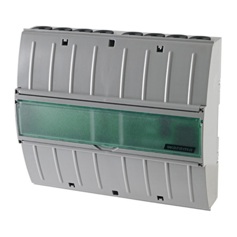
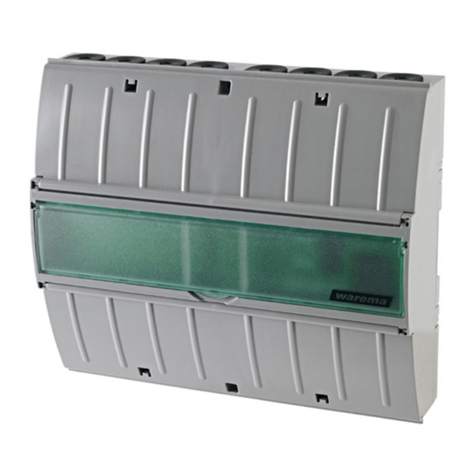
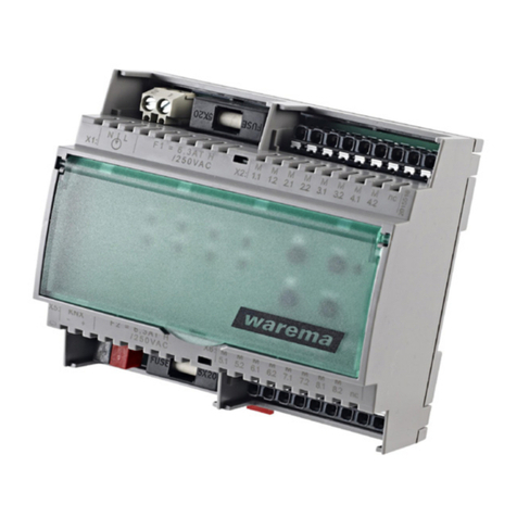
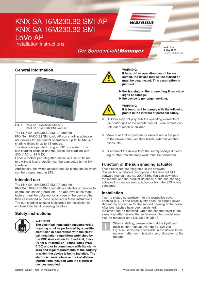
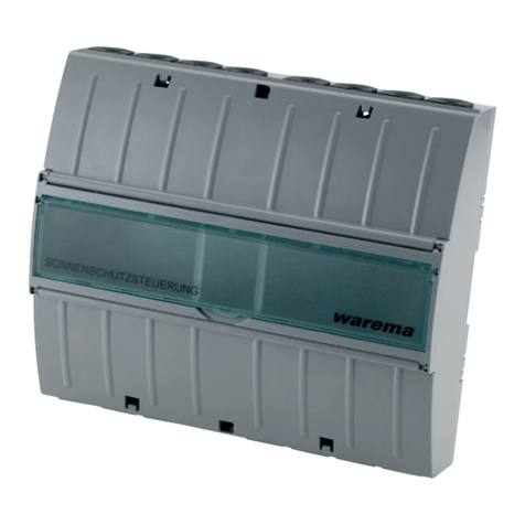
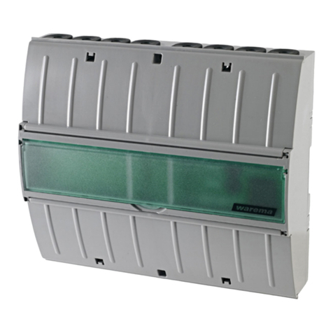
Fig. 1 LONMSE 6M230 in DIN rail-mounted housing (REG)
The LONMSE 6M230 is a LON®actuator for the centralized
and local control of up to six sun shading drives in four
mutually independent groups. Alternatively, four mutually in-
dependent sun shading drives and, in addition, four lamps
that can be switched independently of each other can be
connected. Central operation is provided by connecting a
LON®FTT-10 twisted pair network; for local operation, op-
erating elements can be connected to the device (sunblind
push button, light switch). The drive and LONMSE 6M230
are supplied via a 230 VAC control line. The sun shading
drives and the lighting systems can also have a separate
power supply.
Intended use
The LONMSE 6M230 was developed to control sun shad-
ing and lighting systems. The approval of the manufacturer
must be obtained for uses outside of the purposes listed in
these instructions.
Safety instructions
WARNING
The electrical installation (assembly)/
dismantling must be performed by a certi-
fied electrician in accordance with VDE
0100 and/or with the standards and legal
requirements of the country in which the
device is being installed. The electrician
must observe the installation instructions
included with the electrical devices sup-
plied.
WARNING
If hazard-free operation cannot be as-
sumed, the device may not be started or
must be deactivated. This assumption is
justified if:
Installation instructions
LONMSE 6M230
Valid from
1 October 2022
Keep for future use.
warema_816830_alhb_en_v4•2022-10-01We reserve the right to make technical modifications
2
Remove the terminal covers:
Insert a suitable screwdriver
into the notch!
Fig. 2 Removing the terminal covers (REG variant)
■ The motor control unit is electrically connected ac-
cording to the wiring diagram on the back of this
page (see Fig. 6 and Fig. 7).
Commissioning
After installation has been completed and the supply volt-
age has been connected, the sun shading system can be
operated on-site via the connected push button or the op-
tionally available manual operating unit MABE 12. The fol-
lowing table informs you on which sun shading drives can
be controlled using the connected sunblind push buttons
(factory setting, can be changed later):
Sunblind push button
at input Controls motor
1 (E3.1 / E3.2) 1
2 (E4.1 / E4.2) 2
3 (E5.1 / E5.2) 3
4 (E6.1 / E6.2) 4, 5, 6
However, to centrally operate the system and set up the
convenience and safety functions, the LonWorks network
must be put into operation. This is described in the soft-
ware documentation of your control unit. Contact your sys-
tem integrator in this matter.
Service button and status LEDs: The LONMSE printed
circuit board has a red and a green status LED and a ser-
vice button (see Fig.3). Perform a simple function test: Af-
ter the supply voltage is switched on or after briefly press-
ing the service button, the green LED lights up for approx.
0.5 seconds and then goes out. If the LED lights up con-
tinuously, this indicates a device fault. In this case, contact
your system integrator. After the supply voltage is switched
on, the red LED lights up for up to 20 seconds. As soon as
the device is ready for operation, this LED begins flashing
irregularly. If it lights up continuously, this indicates a de-
vice fault. In this case, contact your system integrator.
ITake suitable precautions to prevent damage due
to electrostatic discharge!
001358799800 LONMSE6 001358799800 LONMSE6
F1
F1
Pull off the bar code
label
E
3.2
E
3.1
123456789X5
P
E
2.2
P
E
2.1
E
1.2
E
1.1P
St1
001358799800 LONMSE6 001358799800 LONMSE6
Fig. 3 LONMSE 6M230I AP (top) or REG (bottom)
Function of the LONMSE 6M230I
Convenience and safety functions
These functions have been integrated in your software and
customized according to your wishes. A detailed descrip-
tion can be found in the software documentation of your
sun shading control system.
Local operation
 By briefly pressing the sunblind push button (< 0.6 sec-
onds), you can adjust the sun shading system in small
steps.
 If the push button is pressed for between 0.6 and
2.6seconds, a move command is triggered and the
sun shading system moves roughly for as long as you
keep the button pressed.
 If the push button is pressed for longer than 2.6 sec-
onds, the sun shading system moves to the upper or
lower limit position. To stop the motion, briefly press the
button for the direction opposite to the direction of the
move command.
Maintenance
There are no parts inside the device that require
maintenance. In the event of a malfunction, the built-
in miniature fuses may only be replaced by a certified
electrician.
Cleaning
Clean the housing with a soft, dry cloth. Do not use
detergents, cleaning agents, solvents, abrasive substances
or steam cleaners!
Liability
Failure to comply with the product information in these
instructions and any use of the device other than its
intended use may result in the manufacturer refusing to
honour warranty claims for product damage. In this case,
liability for secondary harm to persons or damage to
property will also be excluded. Observe the information in
the operating instructions for your sun shading system. The
automatic or manual operation of the sun shading system
while iced over and the use of the sun shading system
during severe weather may cause damage and must be
prevented by the operator through suitable precautions.
Obligations for the disposal of electrical
devices
A marking with this symbol indicates the following
obligations under the scope of legal regulations:
 The owner of this electrical device must dispose of it
separately from unsorted municipal waste for further
recycling.
 Used batteries and accumulators that are not enclosed
in the old device, as well as lamps/bulbs that can be
removed from the old device without breaking, must be
disposed of separately.
 Distributors of electrical devices and disposal companies
are obliged to take back the equipment free of charge
.
 The owner must take it upon themselves to delete any
personal data contained in the electrical device prior to
disposal.
3
warema_816830_alhb_en_v4•2022-10-01 We reserve the right to make technical modifications
Technical data
LONMSE 6M230
230 VAC supply Min. Typ. Max. Unit
Operating voltage 198 230 253 V AC
Quiescent current
consumption, primary
13 18 25 mA
Temperature fuse, primary 131 135 °C
Drive output
Switching capacity at 230
V AC / cos ϕ0.6
500 VA
Light outputs
(Total power of outputs A1.1...A1.4)
230V AC halogen lamps* 2.0* kW
230V AC bulbs* 2.0* kW
Fluorescent tubes* 163 μF 1.5* kVA
*Total power of all 4 outputs. If lamps are controlled, the
miniature fuse F1 / 6.3AT can be replaced by a 10AT fuse.
Input LON®FTT-10
Inputs for local operating elements (sunblind push button,
light switch, light push button/push button, 1-pin)
Local voltage active 8 24 36 V DC
Local current active 1 1.5 2 mA
Local voltage inactive -0.5 0 1.5 V DC
Housing
Dimensions See Fig. 4, 5, 6
Degree of protection/safety class
Degree of protection AP/
REG
IP30
Degree of protection (PE
is looped through)
I
Ambient conditions
Operating temperature 0 20 40 °C
Storage temperature 0 20 60 °C
Humidity
(not condensing)
10 40-60 85 %RH
Degree of soiling 2
Connection
Supply line, drives, push
buttons
Screwed terminals
LonWorks® network Connectors
Terminals
Supply line, drives, push
buttons
0.5 ... 2.5 mm2
LonWorks® network 0.6 ... 0.8 mm ∅
Miscellaneous
Conformity
Available at www.warema.de/ce
This device complies with the EMC directives for use in
residential and commercial areas.
Location of use Clean ambient conditions
Article numbers
LONMSE 6M230 AP 1002744
LONMSE 6M230 REG 1002611
Manual control panel
12 inputs (MABE 12)
1002631
WAREMA Renkhoff SE
Hans-Wilhelm-Renkhoff-Strasse 2
97828 Marktheidenfeld
Germany
LON®and LonWorks®are trademarks of the Echelon Cor-
poration and are registered in the USA and in other coun-
tries.
210 mm 180 mm
60 mm
119 mm
184 mm
-
Fig. 4 Dimensions of surface-mounted housing (AP), 12 MW
60 mm
95 mm
90 mm
210 mm /12MW *Conforms to the DIN 43880
standard for built-in
installation equipment.
4M230I 12 MW / 210mm
2M230I 9 MW / 157mm
Fig. 5 Dimensions of rail-mounted housing (REG), 12 MW
warema_816830_alhb_en_v4•2022-10-01We reserve the right to make technical modifications
4
PE PE PE PE NNLL
X1
98765432198
A
1.1
A
1.2
A
1.3
A
1.4
E
3.2
E
3.1
7654321
123456789123456789
987654321987654321
X5
N
Power line provided by
customer
230V AC / 50Hz/16A
3x1,5mm2
All motor lines
H05RR-F4G0.75 mm2
132
F1
6,3 AT
Max. total current
per supply 15 A
To next
components
Plug and
socket
connection
LONMSE
6M230
M5 M6 M1 M2 M3 M4
1
PE PEN
brbl
132
MM
1
brbl
---------------- network 2 ---------------
X2
-- Motor 1 -- ----------- Motor 2 ----------- -- Motor 3 -- -- Motor 4 --
Status-
LED´s
Service-
push button
X6
LL
11 32 23
M
1
M
1
NNNN
brbl
X3
PE PE
11 32 23
M
1
M
1
PE PEN
brbl
X4
N
F2
6,3 AT
F3
6,3 AT
P
E
2.2
P
E
2.1
E
1.2
E
1.1 PE
6.2
E
6.1 P
E
5.2
P
E
5.1
E
4.2
E
4.1PX7
AABB
LONWORKS®-NetworkLONWORKS®-Netwprk
Output to next
component
Input from previous component
JY(St)Y 2x2x0,8mm ø
max. cable length
50m
E
3.2
E
3.1
123456789X5
P
21
P
0
All push button lines
JY(St)Y 2x2x0,8 mm ø
Connection example:
Sunshade push button
N
L
PE
N
L
PE
Sunshade push button
1234
St1
Attention:
Only one motor may be
connected per motor
terminal set.
Parallel connection will damage
the motor!
Connector for hand-held
control panel, 12 inputs
(MABE 12)
gnyl bk bk
gnyl bl br bk gnyl gnyl bk bl br bk gnyl gnyl bk
Fig. 6 Wiring diagram, LONMSE 6M230 / 6 drives
PE PE PE PE NNLL
X1
98765432198
A
1.1
A
1.2
A
1.3
A
1.4
E
3.2
E
3.1
7654321
123456789123456789
987654321987654321
X5
N
Supply line (lights) provided by customer
230V AC / 50Hz/16A
3x1,5mm
2
All motor lines
H05RR-F4G0.75 mm
2
F1
6,3 AT*
Max. total current
per supply 15 A
To next
components
Plug and
socket
connection
LONMSE
6M230
M1 M2 M3 M4
PE PEN
------------------ Netz 2 --------------------------------------- Netz 1 ---------------------
X2
-- Motor 1 -- ----------- Motor 2 ----------- -- Motor 3 -- -- Motor 4 --
Status-
LED´s
Service-
push button
X6
LL
11 32 23
M
1
M
1
NNNN
brbl
X3
PE PE
11 32 23
M
1
M
1
PE PEN
brbl
X4
N
F2
6,3 AT
F3
6,3 AT
P
E
2.2
P
E
2.1
E
1.2
E
1.1 PE
6.2
E
6.1P
E
5.2
P
E
5.1
E
4.2
E
4.1PX7
AABB
LONWORKS®-NetworkLONWORKS®-Network
Output to next
component
Input from previous
component
JY(St)Y 2x2x0,8mm ø
Max. cable lenght
50m
123456789X5
E
2.2
P
E
2.1
E
1.2
E
1.1P
1
P
All push button lines
JY(St)Y 2x2x0,8 mm ø
Supply line (drive) provided by customer
230V AC / 50Hz/16A
3x1,5mm
2
Max. total current
per supply15 A
connection example for light:
light push buttons are always
connected to inputs
E1.1 / E1.2 / E2.1 / E2.2!
N
L1
PE
N
L1
PE
N
L2
PE
N
L2
PE
Sunshade push button
Light push
button
1234 1234
50m
E
3.2
E
3.1
123456789X5
P
21
P
0
All push button lines
JY(St)Y 2x2x0,8 mm ø
connection example
Sunshade push button
St1
Attention: Only one motor may be
connected per motor terminal set.
Parallel connection will damage
the motor!
Multiple outside lines (phases may be used in a
systemif they are fed through a common earth
leakage cicuit breaker. Attention: All power circuits
must be deactivated during maintenance work.
Max. cable lenght
Connector for hand-held
control panel, 12 inputs
(MABE 12)
brbl bk gnye gnye bk brbl bk gnye gnye bk
*When controlling lights,
a fuse of max. 10 AT
may be used.
Fig. 7 Wiring diagram, LONMSE 6M230 / 4 drives and 4 lamps

Other WAREMA Controllers manuals

WAREMA LONMPM 8DI User manual

WAREMA

WAREMA LONMPM 8DI User manual

WAREMA KNX secure Series User manual

WAREMA

WAREMA KNX secure Series User manual

WAREMA KNX SA 4MDC.8 AP User manual

WAREMA

WAREMA KNX SA 4MDC.8 AP User manual

WAREMA KNX SA 2M230 REG User manual

WAREMA

WAREMA KNX SA 2M230 REG User manual

WAREMA KNX SA Series User manual

WAREMA

WAREMA KNX SA Series User manual

WAREMA KNX secure Series User manual

WAREMA

WAREMA KNX secure Series User manual

WAREMA KNX SA 4MDC.8 AP User manual

WAREMA

WAREMA KNX SA 4MDC.8 AP User manual

WAREMA KNX 2024236 User manual

WAREMA

WAREMA KNX 2024236 User manual

WAREMA KNX SA 2M230 REG User manual

WAREMA

WAREMA KNX SA 2M230 REG User manual

WAREMA WMS SA 1 UP User manual

WAREMA

WAREMA WMS SA 1 UP User manual

WAREMA BACnet 4M230.8I AP User manual

WAREMA

WAREMA BACnet 4M230.8I AP User manual

WAREMA 4M230.12 2Down REG User manual

WAREMA

WAREMA 4M230.12 2Down REG User manual

WAREMA Omnexo 1M230 UP User manual

WAREMA

WAREMA Omnexo 1M230 UP User manual

WAREMA KNX SA 2M230 AP Series User manual

WAREMA

WAREMA KNX SA 2M230 AP Series User manual

WAREMA KNX SA 4MDC REG User manual

WAREMA

WAREMA KNX SA 4MDC REG User manual

WAREMA Omnexo 2M230 REG User manual

WAREMA

WAREMA Omnexo 2M230 REG User manual

WAREMA 1MPF.4 UP User manual

WAREMA

WAREMA 1MPF.4 UP User manual

WAREMA KNX SA 16M230 SMI REG User manual

WAREMA

WAREMA KNX SA 16M230 SMI REG User manual

WAREMA KNX SA 16M230.32 SMI AP User manual

WAREMA

WAREMA KNX SA 16M230.32 SMI AP User manual

WAREMA Omnexo 2M230 AP User manual

WAREMA

WAREMA Omnexo 2M230 AP User manual

WAREMA LONMSE 2M230 Manual

WAREMA

WAREMA LONMSE 2M230 Manual

WAREMA KNX MSE 6M230 Series User manual

WAREMA

WAREMA KNX MSE 6M230 Series User manual

WAREMA LONMSE 2M230I Manual

WAREMA

WAREMA LONMSE 2M230I Manual

WAREMA KNX SA 16M230.32 SMI AP User manual

WAREMA

WAREMA KNX SA 16M230.32 SMI AP User manual

Popular Controllers manuals by other brands

Bpt KX8O16A Technical manual

Bpt

Bpt KX8O16A Technical manual

CRE BTB COMPACT quick start

CRE

CRE BTB COMPACT quick start

Siskiyou MC1100e user manual

Siskiyou

Siskiyou MC1100e user manual

EWC Controls ULTRA-ZONE ULTRA-TALK UT-3000 manual

EWC Controls

EWC Controls ULTRA-ZONE ULTRA-TALK UT-3000 manual

Acuity Controls ECLYPSE A1000 installation guide

Acuity Controls

Acuity Controls ECLYPSE A1000 installation guide

URC MRX-20 owner's manual

URC

URC MRX-20 owner's manual

ABB M2305 manual

ABB

ABB M2305 manual

Radial Engineering MC3 user guide

Radial Engineering

Radial Engineering MC3 user guide

Datapath VSN Series quick start guide

Datapath

Datapath VSN Series quick start guide

Engineered air EngA G-TRAC2 Installation, operation and maintenance manual

Engineered air

Engineered air EngA G-TRAC2 Installation, operation and maintenance manual

Mitsubishi Electric FX3U-4DA-ADP user manual

Mitsubishi Electric

Mitsubishi Electric FX3U-4DA-ADP user manual

Fujitsu TeamPoS 36 Series Installation

Fujitsu

Fujitsu TeamPoS 36 Series Installation

dixell EMERSON XR30D Installing and operating instructions

dixell

dixell EMERSON XR30D Installing and operating instructions

Novus N2000 instruction manual

Novus

Novus N2000 instruction manual

Sit 610 AC3 quick start guide

Sit

Sit 610 AC3 quick start guide

RUBETEK SC-1 manual

RUBETEK

RUBETEK SC-1 manual

BLOCKsignalling SEC1A-DCC manual

BLOCKsignalling

BLOCKsignalling SEC1A-DCC manual

Sunlover SL6RR manual

Sunlover

Sunlover SL6RR manual

manuals.online logo
manuals.online logoBrands
  • About & Mission
  • Contact us
  • Privacy Policy
  • Terms and Conditions

Copyright 2025 Manuals.Online. All Rights Reserved.