SAE J2716 User manual

SAE J2716 (SENT) Gateway User’s Manual
for SENT-RS232 and SENT-CAN
CHANGES
DATE
DESCRIPTION
BY
20.4.2020
Initial Release
MM
2.2.2020
Draft
JJ, MM

SAE J2716 Gateway User’s Manual
MACH SYSTEMS s.r.o.
www.machsystems.cz
Page 2of 17
info@machsystems.cz
Contents
1 About............................................................................................................................................... 4
2 Introduction..................................................................................................................................... 4
3 Technical Specification.................................................................................................................... 4
4 Hardware......................................................................................................................................... 6
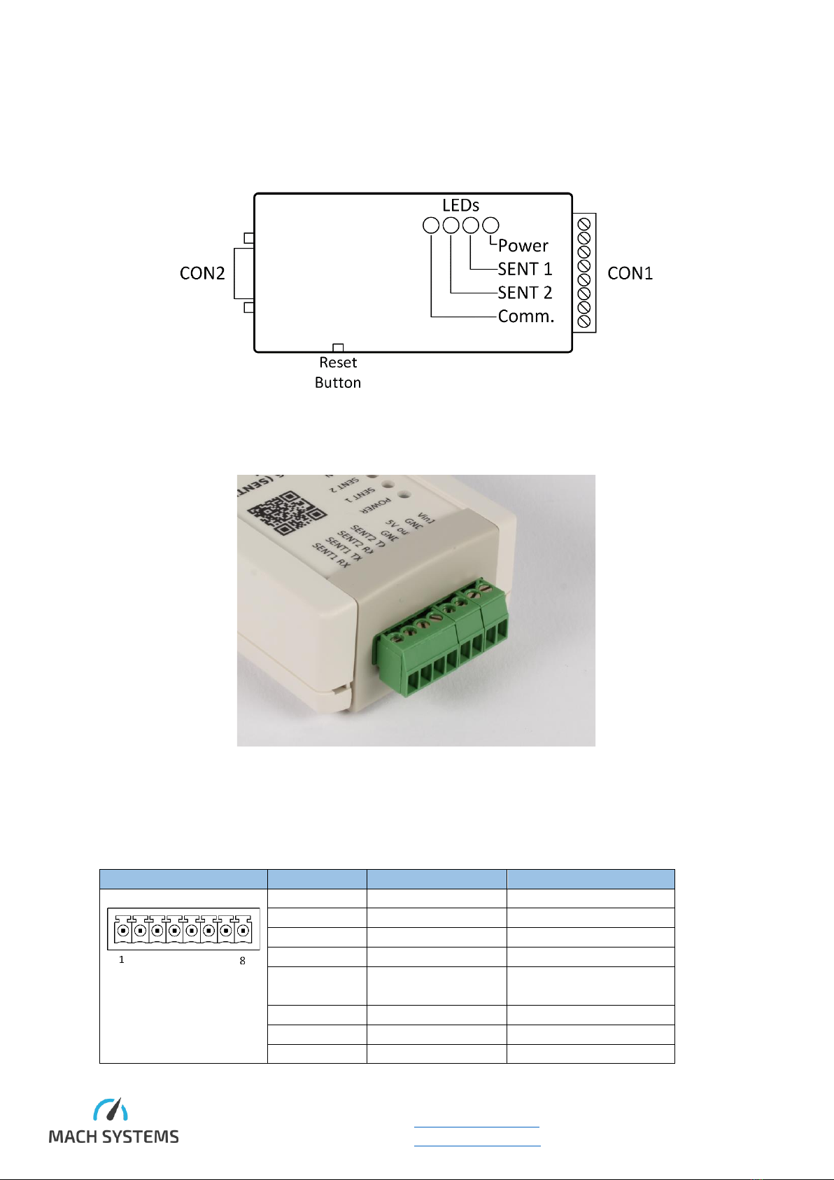
4.1 Overview.................................................................................................................................. 6
4.2 Connectors .............................................................................................................................. 6
4.2.1 CON 1............................................................................................................................... 6
4.2.2 CON 2............................................................................................................................... 7
4.3 LED Status Information............................................................................................................ 7
4.4 Power....................................................................................................................................... 7
4.4.1 SENT-RS232 ..................................................................................................................... 7
4.4.2 SENT-CAN ........................................................................................................................ 8
4.5 CAN Bus Termination .............................................................................................................. 8
4.6 Factory Reset........................................................................................................................... 8
4.7 Firmware Update..................................................................................................................... 9
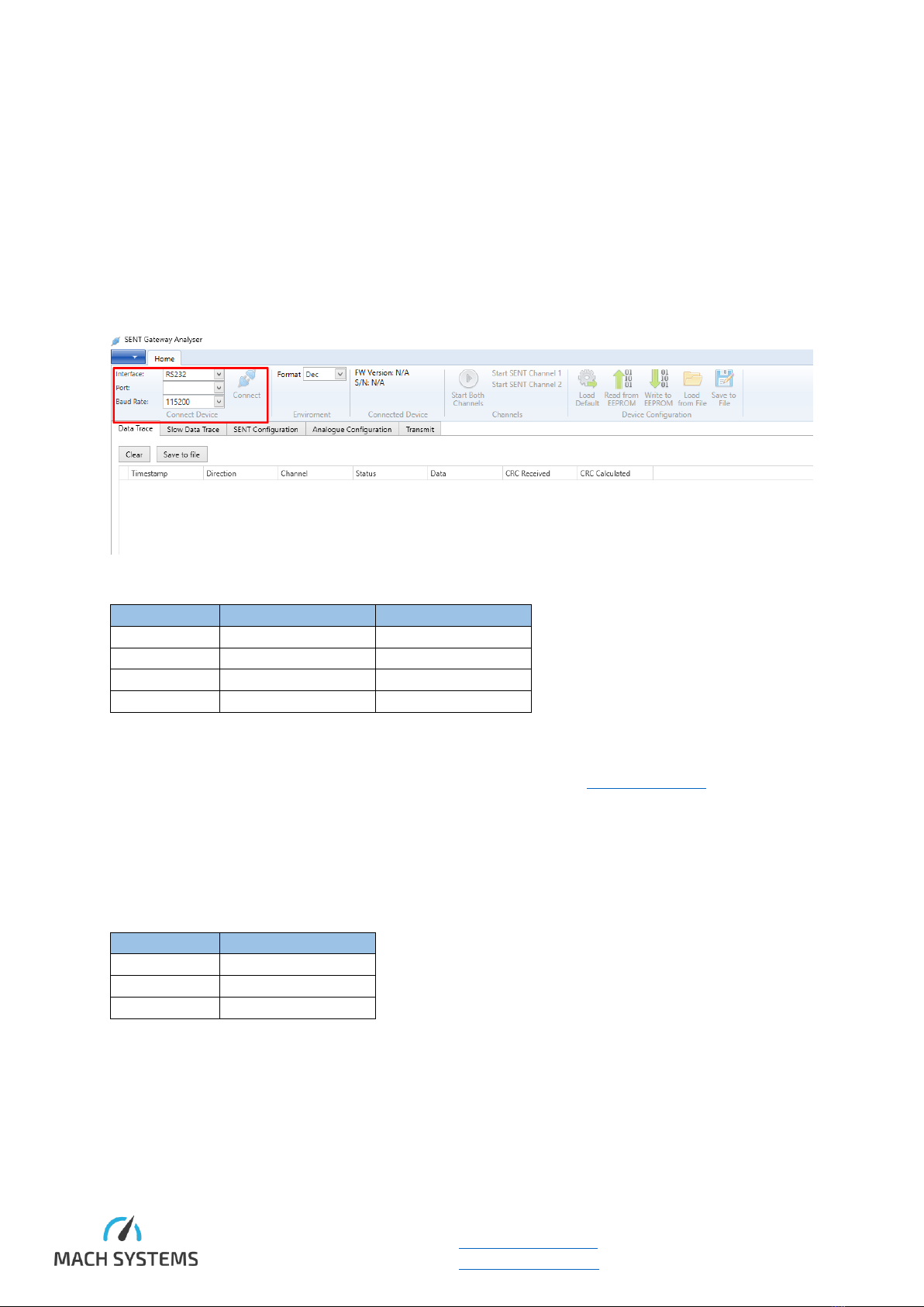
5 SENT Gateway Analyser................................................................................................................. 10
5.1 Connection ............................................................................................................................ 10
5.1.1 SENT-RS232 ................................................................................................................... 10
5.1.2 SENT-CAN ...................................................................................................................... 10
5.1.3 Connect the Device........................................................................................................ 11
5.2 Channel Configuration........................................................................................................... 11
5.3 Start Channel......................................................................................................................... 12
5.4 Transmit Message ................................................................................................................. 13
5.5 Data Analysis ......................................................................................................................... 14
6 Legal Information .......................................................................................................................... 15
6.1 Usage Warning ...................................................................................................................... 15
6.2 Disposal and Recycling Information ...................................................................................... 15
6.3 Declaration of Conformity..................................................................................................... 16
6.4 Patents, Copyrights and Trademarks .................................................................................... 17
7 Ordering Information .................................................................................................................... 17
8 Contact .......................................................................................................................................... 17

SAE J2716 Gateway User’s Manual
MACH SYSTEMS s.r.o.
www.machsystems.cz
Page 3of 17
info@machsystems.cz
List of Tables
Table 1 Technical Specification ............................................................................................................... 5
Table 2 Connector 1 Pin Assignment....................................................................................................... 6
Table 3 Connector 2 Pin Assignment....................................................................................................... 7
Table 4 LED Function Description............................................................................................................ 7
Table 5 SENT-RS232 Default Communication Parameters.................................................................... 10
Table 6 SENT-CAN Default Communication Parameters....................................................................... 10
Table 7 Ordering Codes for SAE J2716 Gateway................................................................................... 17
List of Figures
Figure 1 Top side Layout.......................................................................................................................... 6
Figure 2 CON 1 - Terminal Connector...................................................................................................... 6
Figure 3 SENT-RS232 Power.................................................................................................................... 7
Figure 4 SENT-CAN Power ....................................................................................................................... 8
Figure 5 SENT-CAN Bus Termination....................................................................................................... 8
Figure 6 Reset Switch .............................................................................................................................. 9

SAE J2716 Gateway User’s Manual
MACH SYSTEMS s.r.o.
www.machsystems.cz
Page 4of 17
info@machsystems.cz
1About
This document contains a description of the hardware’s properties and general instructions for using
the SENT-RS232 and SENT-CAN with a computer with the SENT Gateway Analyser application, or for
connecting the gateway to another system.
2Introduction
Both SENT-RS232 and SENT-CAN gateways offer two bi-directional SAE J2716 (SENT - Single Edge
Nibble Transmission) channels. The SENT-RS232 features a RS-232 interfaces, whilst SENT-CAN offers
a CAN bus interface.
The gateways also offer two precise analogue outputs (12-bit, 0 - 4.095 V) that can be mapped onto
incoming SENT data. Conversion parameters can be configured. This allows an easy way to convert
signal values from SENT directly into an analogue voltage value.
Fast, Short Serial, and Enhanced Serial message formats are supported. The user can configure channel
parameters (direction, tick time, nibble count, filtration) and store the configuration into the device’s
non-volatile memory. Each SENT channel can be configured independently to suit all possible use
cases: 2 RX channels / 1 RX and 1 TX channel / 2 TX channels.
An intelligent filtration of incoming SENT frames has been introduced so that RS-232 or CAN
communication does not get overloaded. The CAN variant offers configurable CAN Identifiers for both
TX and RX which allows multiple devices to be used simultaneously on the same CAN bus. The device’s
firmware is upgradable from PC.
3Technical Specification
SENT
Channels
2x bi-directional SENT channel
each channel configurable as RX or TX
Specification
SAE J2716:2016
Pause Pulse Support
SPC Mode Support
Tick Time
3 - 90 us (different on request)
Data Nibbles
1 - 6
Message Format
Fast, Short Serial, Enhanced Serial
RX Message Filtration
No filtration, On change, Skip frames
Analogue Outputs
Channels
2x 12-bit DAC
Voltage Range
0 - 4.095 V (internal precise reference)
Mapping
Off, SENT1, SENT2
Configurable Parameters
Start Bit, Bit Length, Multiplier, Offset,
Min/Max Voltage
General
Configuration
Non-volatile memory for storing configuration
of SENT channels, communication
parameters, and analogue channels

SAE J2716 Gateway User’s Manual
MACH SYSTEMS s.r.o.
www.machsystems.cz
Page 5of 17
info@machsystems.cz
PC application
Free-of-charge PC application (Windows) for
device configuration, reception and
transmission of SENT Fast/Slow frames
Firmware
Upgradable from PC
Microcontroller
16-bit DSP
Communication Interface
Protocol
Binary protocol for easy integration
SENT-RS232
RS232: 115200, 8N1
SENT-CAN
CAN bus with configurable parameters:
Baud Rate, Sample Point, RX/TX CAN
Identifiers
This allows multiple devices on the same bus
Electrical and Mechanical
Power
9 - 30 V DC (polarity protection)
5 V DC output for sensors (limited to 200 mA)
Consumption
50mA @ 12 V
(5V output is not considered)
LEDs
3x Status Indicator
1x Power
Button
1x Tactile switch (reset factory defaults)
Connectors
1x D-SUB-9 F
1x Terminal Block 8-pin, 3.5 mm pitch
Dimensions (L x W x H)
108 x 54 x 30 mm
Weight
80 g
Operating Temperature
-20 to 60 °C
Protection
IP40
Placement
Table (adhesive pads included)
DIN-rail mount (clip sold separately)
Table 1 Technical Specification

SAE J2716 Gateway User’s Manual
MACH SYSTEMS s.r.o.
www.machsystems.cz
Page 6of 17
info@machsystems.cz
4Hardware
4.1 Overview
The gateway has two connectors, 4 LEDs, and a reset button.
Figure 1 Top side Layout
Figure 2 CON 1 - Terminal Connector
4.2 Connectors
4.2.1 CON 1
Terminal Block
Pin
Function
Note
Front view
1
SENT 1 RX
input
2
SENT 1 TX
output
3
SENT 2 RX
input
4
SENT 2 TX
output
5
GND
internally connected to
DSUB9 pin 5
6
5V output
200mA protection
7
GND (Power In-)
connected to pin 5
8
Vin1 (Power In+)
Table 2 Connector 1 Pin Assignment

SAE J2716 Gateway User’s Manual
MACH SYSTEMS s.r.o.
www.machsystems.cz
Page 7of 17
info@machsystems.cz
Both SENT-RS232 and SENT-CAN can be powered over CON 1: pins 8 and 9. CAN variant can also be
powered via CON 2: pins 9 and 3. All GND pins are connected throughout the device. Hence, there is
no galvanic isolation.
4.2.2 CON 2
D SUB 9 Female
Pin Number
RS-232 variant
CAN variant
Front view
1
2
TxD (output)
CAN_L
3
RxD (input)
GND (Power In-)
4
5
GND
GND (internally connected
to pin 3)
6
AO1
AO1
7
CAN_H
8
AO2
AO2
9
Vin2 (Power In+)
Table 3 Connector 2 Pin Assignment
4.3 LED Status Information
The four LEDs provide the following status information:
LED
Colour
State
Meaning
Power
Green
On
The device is powered
SENT 1
Yellow
Off
Channel is stopped
Slow blinking
Reception in progress
Fast blinking
Transmission in progress
SENT 2
Yellow
Off
Channel is stopped
Slow blinking
Reception in progress
Fast blinking
Transmission in progress
Communication
Green / Red
Green flash
Communication packet received
Red flash
Communication packet error
Table 4 LED Function Description
4.4 Power
The device needs an external power supply 9 - 30 V DC.
4.4.1 SENT-RS232
Power is provided over CON 1.
Figure 3 SENT-RS232 Power

SAE J2716 Gateway User’s Manual
MACH SYSTEMS s.r.o.
www.machsystems.cz
Page 8of 17
info@machsystems.cz
4.4.2 SENT-CAN
The SENT-CAN device offers two possibilities to power the device - over CON1 (like SENT-RS232) or
over CON2 (DSUB9).
Figure 4 SENT-CAN Power
4.5 CAN Bus Termination
The SENT-CAN does not have an internal termination resistor on the CAN bus. Therefore, a proper
termination of the CAN bus is needed. The user needs to make sure the CAN bus is properly terminated
at both ends.
Figure 5 SENT-CAN Bus Termination
4.6 Factory Reset
The reset button is located on the side of the device. For resetting to factory defaults, power the
device, wait a few seconds and then press and hold the button for 10 seconds. The button can be
pressed by tweezers or a pen.

SAE J2716 Gateway User’s Manual
MACH SYSTEMS s.r.o.
www.machsystems.cz
Page 10 of 17
info@machsystems.cz
5SENT Gateway Analyser
The SENT Gateway Analyser is a Windows application that provides the user an easy way to use the
gateway. The application is provided free-of-charge and allows to configure SENT channels and
analogue output channels, save and load the runtime and non-volatile configuration, and receive and
transmit Fast and Slow SENT messages.
5.1 Connection
5.1.1 SENT-RS232
Make sure your computer has an on-board COM port or a USB-COM adapter.
Default Communication Parameters:
Parameter
Value
Note
Baud Rate
115200 Baud
Data bits
8
not configurable
Parity
None
not configurable
Stop bit
1 bit
not configurable
Table 5 SENT-RS232 Default Communication Parameters
5.1.2 SENT-CAN
The SENT Gateway application works with CAN interfaces by Kvaser (www.kvaser.com). Therefore, a
Kvaser interface is needed in order to use the application.
Make sure that Kvaser driver is installed on your computer.
Select CAN channel, baud rate and CAN ID for both directions.
Default Communication Parameters:
Parameter
Value
Baud Rate
500 KBaud
PC TX CAN Id
0x123 (Standard)
PC TX CAN Id
0x321 (Standard)
Table 6 SENT-CAN Default Communication Parameters

SAE J2716 Gateway User’s Manual
MACH SYSTEMS s.r.o.
www.machsystems.cz
Page 11 of 17
info@machsystems.cz
5.1.3 Connect the Device
1) Click on Connect button
2) If the gateway is correctly powered and connected to the computer, its serial number and
firmware version, and the current configuration will be loaded:
5.2 Channel Configuration
The gateway has two independent SENT channels that can be configured in “SENT Configuration”
tab. After modifying the configuration, don’t forget to write it into the gateway by clicking to “Write
Configuration” button!

SAE J2716 Gateway User’s Manual
MACH SYSTEMS s.r.o.
www.machsystems.cz
Page 12 of 17
info@machsystems.cz
You can also save the SENT and analogue channels configuration into gateway’s EEPROM, which
makes the gateway to load this configuration on power-up.
5.3 Start Channel
After a configuration is written into the device, one or both channels can be started.

SAE J2716 Gateway User’s Manual
MACH SYSTEMS s.r.o.
www.machsystems.cz
Page 13 of 17
info@machsystems.cz
5.4 Transmit Message
If your configuration contains at least one Tx channel, you can fill data to send in Transmit tab. Fill
your data and click to Transmit button.
You can prepare more messages by adding more rows. You can also remove them with Remove Row
button.
The table above do not behave as a scheduler. Only one row will be periodically transmitted onto
the SENT bus.

SAE J2716 Gateway User’s Manual
MACH SYSTEMS s.r.o.
www.machsystems.cz
Page 15 of 17
info@machsystems.cz
6Legal Information
6.1 Usage Warning
WARNING FOR ALL USERS
WARNING! - YOUR USE OF THIS DEVICE MUST BE DONE WITH CAUTION AND A FULL UNDERSTANDING OF THE RISKS!
THIS WARNING IS PRESENTED TO INFORM YOU THAT THE OPERATION OF THIS DEVICE MAY BE DANGEROUS. YOUR ACTIONS
CAN INFLUENCE THE BEHAVIOR OF A DISTRIBUTED EMBEDDED SYSTEM, AND DEPENDING ON THE APPLICATION, THE
CONSEQUENCES OF YOUR IMPROPER ACTIONS COULD CAUSE SERIOUS OPERATIONAL MALFUNCTION, LOSS OF
INFORMATION, DAMAGE TO EQUIPMENT, AND PHYSICAL INJURY TO YOURSELF AND OTHERS. A POTENTIALLY HAZARDOUS
OPERATING CONDITION IS PRESENT WHEN THE FOLLOWING TWO CONDITIONS ARE CONCURRENTLY TRUE: THE PRODUCT IS
PHYSICALLY INTERCONNECTED TO A REAL DISTRIBUTED EMBEDDED SYSTEM; AND THE FUNCTIONS AND OPERATIONS OF THE
REAL DISTRIBUTED EMBEDDED SYSTEM ARE CONTROLLABLE OR INFLUENCED BY THE USE OF THE CAN NETWORK. A
POTENTIALLY HAZARDOUS OPERATING CONDITION MAY RESULT FROM THE ACTIVITY OR NON-ACTIVITY OF SOME
DISTRIBUTED EMBEDDED SYSTEM FUNCTIONS AND OPERATIONS, WHICH MAY RESULT IN SERIOUS PHYSICAL HARM OR
DEATH OR CAUSE DAMAGE TO EQUIPMENT, DEVICES, OR THE SURROUNDING ENVIRONMENT.
WITH THIS DEVICE, YOU MAY POTENTIALLY:
•CAUSE A CHANGE IN THE OPERATION OF THE SYSTEM, MODULE, DEVICE, CIRCUIT, OR OUTPUT.
•TURN ON OR ACTIVATE A MODULE, DEVICE, CIRCUIT, OUTPUT, OR FUNCTION.
•TURN OFF OR DEACTIVATE A MODULE, DEVICE, CIRCUIT, OUTPUT, OR FUNCTION.
•INHIBIT, TURN OFF, OR DEACTIVATE NORMAL OPERATION.
•MODIFY THE BEHAVIOR OF A DISTRIBUTED PRODUCT.
•ACTIVATE AN UNINTENDED OPERATION.
•PLACE THE SYSTEM, MODULE, DEVICE, CIRCUIT, OR OUTPUT INTO AN UNINTENDED MODE.
ONLY THOSE PERSONS WHO:
(A) ARE PROPERLY TRAINED AND QUALIFIED WITH RESPECT TO THE USE OF THE DEVICE,
(B) UNDERSTAND THE WARNINGS ABOVE, AND
(C) UNDERSTAND HOW THIS DEVICE INTERACTS WITH AND IMPACTS THE FUNCTION
AND SAFETY OF OTHER PRODUCTS IN A DISTRIBUTED SYSTEM AND THE APPLICATION FOR WHICH THIS DEVICE WILL BE
APPLIED, MAY USE THE DEVICE.
PLEASE NOTE THAT YOU CAN INTEGRATE THIS PRODUCT AS A SUBSYSTEM INTO HIGHER-LEVEL SYSTEMS. IN CASE YOU DO
SO, MACH SYSTEMS s.r.o. HEREBY DECLARES THAT MACH SYSTEMS s.r.o.’s WARRANTY SHALL BE LIMITED TO THE
CORRECTION OF DEFECTS, AND MACH SYSTEMS s.r.o. HEREBY EXPRESSLY DISCLAIMS ANY LIABILITY OVER AND ABOVE THE
REFUNDING OF THE PRICE PAID FOR THIS DEVICE, SINCE MACH SYSTEMS s.r.o. DOES NOT HAVE ANY INFLUENCE ON THE
IMPLEMENTATIONS OF THE HIGHER-LEVEL SYSTEM, WHICH MAY BE DEFECTIVE.
6.2 Disposal and Recycling Information
When this product reaches its end of life, please dispose of it according to your local
environmental laws and guidelines.

SAE J2716 Gateway User’s Manual
MACH SYSTEMS s.r.o.
www.machsystems.cz
Page 17 of 17
info@machsystems.cz
6.4 Patents, Copyrights and Trademarks
All trademarks are the property of their respective owner. Windows is a registered trademark of
Microsoft Corporation in the United States and other countries.
Adobe, the Adobe logo, and Reader are either registered trademarks or trademarks of Adobe Systems
Incorporated in the United States and/or other countries.
Kvaser is a registered trademark of Kvaser AB in Sweden and other countries.
7Ordering Information
Product Number
Description
SENT-RS232
SAE J2716 to RS-232
SENT-CAN
SAE J2716 to CAN bus
DIN-CLIP-1
Clip for mounting on a DIN rail
Table 7 Ordering Codes for SAE J2716 Gateway
8Contact
MACH SYSTEMS s.r.o.
www.machsystems.cz
Czech Republic
Company registration: 29413893
EU VAT number: CZ29413893
Table of contents
Popular Gateway manuals by other brands

ZyXEL Communications
ZyXEL Communications p-2302rl series brochure

NEC
NEC EcoPowerGateway N8142-36F user guide

SpectraLink
SpectraLink MOG710 Installation and administration

Hitron
Hitron CODA-4*8 Series DOCSIS user guide

Motorola
Motorola SURFboard SVG6582 user guide

Milesight
Milesight Urbana GO03 quick start guide