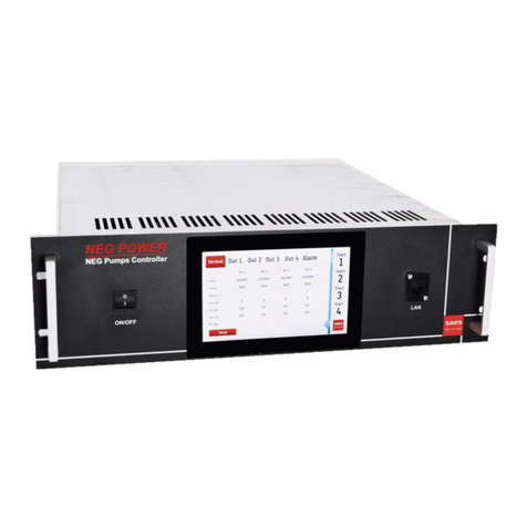
SAES SIP POWER User manual

UDOC – CONTROLLED COPY
M.HIST.0109.23 Rev.1 May 22, 2017
SAES Getters S.p.A. – Italy
www.saesgroup.com
USER MANUAL
SIP POWER
ION Pump Controller

USER MANUAL - SIP POWER ION PUMP CONTROLLER
M.HIST.0109.23 Rev.1 Page 2 of 62
The SIP POWER power supply is used for operating the ION element of NEXTorr family pumps. It
is designed to be used indoor in laboratory conditions.
Security provisions
Symbols on the Product
These symbols appear on the product:
WARNING
High voltage Ground terminal CAUTION
Refer to manual
WARNING
After transportation, the device has to be left idle without mains
voltage for at least 3 hours at the laboratory temperature.
ATTENTION
Inside the instrument and also in the connector and cable for the
ion pump connection, a high voltage is present which is capable of
causing a casualty even without any direct touch.
Manipulation of the high voltage cable and also of the
grounding wire is prohibited during the supply operation.
Likewise, the supply operation without protective covers is
prohibited.
Protect the device against humidity and against penetration of
conductive objects and liquids into the ventilation slots.

USER MANUAL - SIP POWER ION PUMP CONTROLLER
M.HIST.0109.23 Rev.1 Page 3 of 62
INDEX
1.APPLICATION ......................................................................................................................... 5
2.INTRODUCTION ..................................................................................................................... 5
2.1.General description......................................................................................................... 5
2.2.Remote and multi Control ............................................................................................... 5
2.3.Simplified block scheme ................................................................................................. 7
2.4.Scheme of the instrument connection............................................................................. 7
2.5.The front panel of the unit ............................................................................................... 8
2.6.The rear panel of the unit................................................................................................ 8
2.7.The front panel of the unit with LEDs and RS485 interface .......................................... 10
2.8.Supplied accessories .................................................................................................... 10
2.9.Instrument Dimensions and Weight .............................................................................. 11
3.INSTALLATION ..................................................................................................................... 12
3.1.Mounting operation ....................................................................................................... 12
3.2.Electrical connections ................................................................................................... 14
4.OPERATIONS ....................................................................................................................... 15
4.1.Start operations............................................................................................................. 15
4.2.Operating IP supply ...................................................................................................... 15
4.3.Comparators with simple threshold or hysteresis ......................................................... 16
4.4.Operating IP in case of main line interruption ............................................................... 17
5.DISPLAY AND MULTIPLE FUNCTIONS OF KEYS.............................................................. 18
5.1.Display information ....................................................................................................... 18
5.2.Multifunctional keys....................................................................................................... 20
6.SETTINGS and SERVICE MODE MENU.............................................................................. 22
Vout Set Point ............................................................................................................................ 22
Vout Ramp Intv........................................................................................................................... 22
Conversion Rate......................................................................................................................... 22
SW1 Mode and SW1 Thr. ........................................................................................................ 22
SW2 Mode and SW2 Min Thr. and SW2 Max Thr.................................................................. 22
SW3 Mode and SW3 Min Thr. and SW3 Max Thr.................................................................. 23
IP Address, IP Netmask and MAC Address ............................................................................. 23
Keepalive.................................................................................................................................... 23
Backlight Sleep........................................................................................................................... 23
Active Time................................................................................................................................. 23
Int. Temperature......................................................................................................................... 23
Card Type................................................................................................................................... 23
Hw. Rev. and Sw. Ver. ............................................................................................................... 24
Serial Number ............................................................................................................................ 24
7.ABNORMAL SITUATION AND ALARM NOTIFICATION ...................................................... 25
Interlock...................................................................................................................................... 25
Safe ............................................................................................................................................ 25
Arcing ......................................................................................................................................... 25
Over current ............................................................................................................................... 25
Over temperature ....................................................................................................................... 25
Input voltage............................................................................................................................... 26
Output over-voltage.................................................................................................................... 26
Communication .......................................................................................................................... 26
8.THE OUTPUT CONNECTOR FUNCTION ............................................................................ 27
8.1.Pin layout of IN/OUT Interface connector ..................................................................... 27
8.2.Analog Output ............................................................................................................... 28
8.3.RS485 Interface ............................................................................................................ 29

USER MANUAL - SIP POWER ION PUMP CONTROLLER
M.HIST.0109.23 Rev.1 Page 4 of 62
9.Modbus PDU Communication Protocol ................................................................................. 30
9.1.Implementation Notes ................................................................................................... 30
9.2.Registers Map............................................................................................................... 30
9.3.Registers Detailed Description...................................................................................... 32
10.IP - UDP communication protocol ........................................................................................ 46
10.1.Payload for 0x40 – Set Working Parameters Command........................................... 47
10.2.Payload for 0x41 – Set IP Address Command.......................................................... 48
10.3.Payload for 0x80 – Read All Answer Command ....................................................... 48
11.MAINTENANCE AND TROUBLESHOOTING ..................................................................... 52
11.1.IP troubleshooting ..................................................................................................... 52
12.SPECIFICATIONS ............................................................................................................... 53
13.DECLARATION OF CE CONFORMITY .............................................................................. 54
14.INSTRUCTION FOR INSTRUMENT DISPOSAL................................................................. 56
15.PRODUCT CONFIGURATIONS AND ACCESSORIES ...................................................... 57
16.WARRANTY CONDITIONS ................................................................................................. 58
17.SERVICE ............................................................................................................................. 59
17.1.Sales & Service Locations:........................................................................................ 59

USER MANUAL - SIP POWER ION PUMP CONTROLLER
M.HIST.0109.23 Rev.1 Page 5 of 62
1. APPLICATION
SIP POWER is the controller unit designed for operating the ion pump of NEXTorr family.
2. INTRODUCTION
2.1. General description
SIP POWER is the power supply that controls the ion pump (IP) of NEXTorr family. NEXTorr
pumps combine in a very compact and unique design Non Evaporable Getter (NEG) and ion pump
technologies.
SIP POWER can be supplied with alphanumeric display or without display.
The controller version without display is equipped with RS485 interface and 2 status LEDs.
For both solutions, the controller case is a sub-rack 3U 14TE 230mm deep.
Both solutions can be equipped with ETHERNET (to remote control the device) and USB (to record
the device parameters on a USB flash memory) data interfaces, but devices without these
interfaces are also available.
The device is powered by external source of 24Vdc and provides voltage values between 600V
and 6kV to the ion pump.
SIP POWER has an autoranging internal system for measuring the output current.
The current value is shown on the display (or provided through the serial communication in version
without display). The current value is also provided through the ETHERNET communication in nA
units. The serial communication and the ETHERNET communication can also provide the voltage
output value. The current value and the voltage output value are also automatically stored in USB
flash memory if it is connected in its slot.
The SIP POWER has two security signals to provide high voltage values to the ion pump:
the SAFETY connector and the INTERLOCK signal.
A SAFETY pin connector allows managing the supply of the high voltage to the ion pump in total
security. The INTERLOCK contact allows to shut down the high voltage to the ion pump with an
external alarm signal.
SIP POWER has 3 optional data interfaces:
* ETHERNET (to remote control the device)
* USB (to record the device parameters on a USB flash memory),
* RS485 (only available for the version without display).
The device has also a special interface with the DB15 connector compatible with NIOPS devices of
NEXTorr pumps.
2.2. Remote and multi Control
Dedicated software is provided to remotely control the SIP POWER through the ETHERNET
connection. The software allows to control several SIP POWER units at the same time.
All functions and parameters can be easily controlled through the software.
Software allows controlling a single unit or more units at the same time.
Local and remote control are possible contemporarily.
This software is available for Windows and for Linux PCs.
For SIP POWER equipped with RS485 interface a different dedicated software is available (just for
one unit at a time). Serial communication protocol via RS485 is MODBUS RTU (for more details

USER MANUAL - SIP POWER ION PUMP CONTROLLER
M.HIST.0109.23 Rev.1 Page 6 of 62
see the dedicated paragraph).

USER MANUAL - SIP POWER ION PUMP CONTROLLER
M.HIST.0109.23 Rev.1 Page 7 of 62
2.3. Simplified block scheme
2.4. Scheme of the instrument connection

USER MANUAL - SIP POWER ION PUMP CONTROLLER
M.HIST.0109.23 Rev.1 Page 8 of 62
2.5. The front panel of the unit
1. Alphanumeric display
2. START/STOP button to switch on/off the output
3. A/V/W button to change the parameter shown on display; current, voltage or power alternately
4. Torr/Pa/mb button to change the unit of pressure between Torr, Pascal or mbar respectively
5. ON/OFF instrument power switch
2.6. The rear panel of the unit
3 4
1
5
2
6
11
10
7
8 9

USER MANUAL - SIP POWER ION PUMP CONTROLLER
M.HIST.0109.23 Rev.1 Page 9 of 62
6. ETHERNET connector (to remote control the device)
7. USB connector (to record the device parameters on a USB flash memory)
8. SAFETY connector
9. OUTPUT pump connector
10. IN/OUT interface connector with INTERLOCK
11. instrument’s MAININPUT plug

USER MANUAL - SIP POWER ION PUMP CONTROLLER
M.HIST.0109.23 Rev.1 Page 10 of 62
2.7. The front panel of the unit with LEDs and RS485 interface
12. “ON LINE” Status LED: if it is on it means that the instrument is on
13. “HV OUTPUT ACTIVE” Status LED is on when power is issued to the pump
14. RS485 connector
15. ON/OFF instrument power switch
2.8. Supplied accessories
The following accessories are provided with SIP POWER (version 3B0506):
- Power supply 220V – 24 Vdc with shuko wall plug cable
- DB15 plug with PIN to bypass Interlock and Safety connections
- Saes Group USB stick with
oUser manual
oSIP power manager: software for remote control via LAN
oSIP power controller: software for remote control of one unit via RS485
oSAES product brochures
12 14
15
13

USER MANUAL - SIP POWER ION PUMP CONTROLLER
M.HIST.0109.23 Rev.1 Page 11 of 62
2.9. Instrument Dimensions and Weight
SIP POWER dimensions (all configurations) Subrack 3U 14 TE
SIP POWER weight (all configurations) about 1 kg
220V to 24Vdc power supply unit weighs about 300g and its dimensions are about 12x5x3 cm.
MINIMUM SPACE
FOR ION PUMP CABLE
228,5 70,8
256,5
128,5
90
7,555,8
3122,5
111,5
21
20
66,5
3
6

USER MANUAL - SIP POWER ION PUMP CONTROLLER
M.HIST.0109.23 Rev.1 Page 12 of 62
3. INSTALLATION
3.1. Mounting operation
Construction design enables the unit to operate either as a stand-alone version (to be laid on a
table) or as a system version which can be mounted in a rack (rack 3U 19" installation with M3
screws). According to the desired version it is possible to mount/remove four rubber feet.
Stand-alone version
Mounting on panel

USER MANUAL - SIP POWER ION PUMP CONTROLLER
M.HIST.0109.23 Rev.1 Page 13 of 62
Mounting in a rack 3U 19"
Warning
The circulation of cooling air on the upper/bottom left/right side and behind the device must not be
significantly limited when the unit is inserted in a rack or laid on a table.

USER MANUAL - SIP POWER ION PUMP CONTROLLER
M.HIST.0109.23 Rev.1 Page 14 of 62
3.2. Electrical connections
The device can be powered by external source of 24 Vdc with appropriate isolation from main line
via connector Jack pin P1J with central positive contact (maximum current 2A).
It is made available:
- 220V -24 Vcd power supply (provided with version 3B0506)
- battery pack (can be ordered separately)
The IP is connected to the power supply by means of the provided high voltage cable. The
appropriate cable terminal is inserted into the high voltage connector labeled HV. The cable is
locked by rotating the ring against spontaneous disengagement. The same operation must be
done for the opposite end of the cable on the pump side.
Safety pin of safe cable (2 mm plug) must be inserted into the Safety connector.
An enable signal called INTERLOCK must be provided to SIP POWER via IN/OUT interface
connector with a closed contact between pins 6-9 and 1-14 (see plot at Sec. 8.1).
If these safety supports are not available (INTERLOCK and SAFE CONNECTOR) it is possible to
bypass these signals using the provided DB15 plug.
The enclosed DB15 plug (Interlock by shorted pins 6-9 and 1-14) with SAFE pin (shorted to
ground) should be inserted to connector IN/OUT and to connector SAFETY on the rear panel.
Warning
Negative wire of power supply is grounded.
The ground terminal and the outer electrode of the high voltage connector are mutually galvanically
interconnected.
Warning
Connection and disconnection of the high voltage cable are possible only with the power supply
switched off.

USER MANUAL - SIP POWER ION PUMP CONTROLLER
M.HIST.0109.23 Rev.1 Page 15 of 62
4. OPERATIONS
4.1. Start operations
The supply is switched on by pressing the I-O switch into position I. The connection is signaled by
the display turned ON or by the green light of the Status Led ON LINE for version with RS485.
The IP is not electrically powered when the supply is switched on: the word Stop shows on the
display (for more details see the display section).
Some ticks are heard during the starting of the power supply belonging to the automatic
initialization settings.
SIP POWER switches on very rapidly (3-5 seconds) and is immediately ready to locally operate.
Remote communication (Ethernet plus USB module) is available after 30 seconds from the switch
on of the SIP POWER.
During device initialization, the outer electrical circuit is tested. If the interlock plug is not inserted or
some other signal (defined alarm) is present, the display will show the message about the detected
alarm/alarms. Name of alarm/alarms appear and blink on the display. In case of more than one
alarm, their names are shown sequentially.
Even if alarm root is removed (example: interlock sensor is inserted again) the message will stay
visible till the operator intervention. In order to delete the alarm message from display and memory,
the right key (up arrow) must be pressed for 5 seconds.
For more details see chapter 5 “display and multiple functions of keys”.
4.2. Operating IP supply
The IP supply can be switched on by pressing the pushbutton START/STOP on the front panel.
The unit must be switched on only at the recommended starting pressure (see pumps Operating
Instruction Manual for details). The working state of the supply is indicated by the word Active on
the first line of the display (for more details see display section).
When the START button is pressed, the voltage is gradually provided to the pump with a linear
ramp and some ticks related to internal automatic settings can be heard. Those ticks can be heard
also during normal operation.
The current flowing through the pump is shown on the display. Pump voltage, pump current and
output power can be alternatively displayed by pushing the A/V/W button.
Pressure inside the ion pump is roughly estimated from the current value and is shown on the
display (pushing the button Torr/Pa/mb changes the unit of measurement).

USER MANUAL - SIP POWER ION PUMP CONTROLLER
M.HIST.0109.23 Rev.1 Page 16 of 62
The relationship between the values of current and pressure depends on the type and size of used
pump and on the instantaneous pump voltage. To set the parameters of this relationship see
SETTINGS chapter at Sec. 6.
The value <1e-11 Torr shows up when IP current reaches 0 nA (IP current is below the
measurable limit).
Warning
In the case the HV cable is disconnected, the current will be 0nA and the value <1e-11 Torr will
show up as well.
4.3. Comparators with simple threshold or hysteresis
Single Threshold SWITCH 1 comparator.
The device is equipped with an automatic overcurrent protection which switches off the IP supply
after the pump current exceeds the safety value protection adjusted under SW1.
This condition is indicated by an alarm message on the display
After 3÷5 seconds the supply automatically switches on again. If the overcurrent protection level is
exceeded once again, the device switches off repeatedly. After 3 unsuccessful attempts to switch
the supply on automatically, the supply switches off permanently.
After the cause of excessive current is removed (e.g. getting a better vacuum or removing a short
circuit) it is possible to switch on the unit again. To switch on the IP supply unit, it is necessary to
remove the alarm condition (keep right button pressed for 5 seconds) and only after that, press
the START/STOP button.
These functions protect the supply against an excessive load but also protect your pump against
an uncontrolled operation, which could damage it or shorten its lifetime.
On the IN/OUT INTERFACE connector a proper signal that reports current status of the SWITCH
is reported. The same status is shown on the display with the symbol of open/close electric switch
(more details in the display paragraph).
The pin layout of the output connector is described in the Sec. 8.1.
Single Threshold or Hysteresis SWITCHES 2 and 3 comparators
The supply is equipped with other two comparators-switches of the pump current/pressure. These
other two switches, SW2 and SW3, can be used to directly connect the SIP POWER with other
electronic equipment. Their outputs are led to the IN/OUT INTERFACE output connector. As for
SW1, also for SW2 and SW3 the status is shown on the display first line with the symbol of
open/close electric switch (more details in the display paragraph).
Comparator-switch SW1 can works only in Simple working mode.
Comparators-switches SW2 and SW3 can work in Simple working mode or in Window working
mode.
To change working mode see SETTINGS chapter (Sec. 6).

USER MANUAL - SIP POWER ION PUMP CONTROLLER
M.HIST.0109.23 Rev.1 Page 17 of 62
Simple working mode
If the current/pressure is smaller than preset threshold, the indicator on the display and the output
switch of related comparator opens contact on output connector and will stay unchanged until
current/pressure value does not go over threshold value.
If the current/pressure is bigger than preset threshold, the state of the indicator on the display and
the output switch of related comparator closes contact on output connector and will stay
unchanged until current/pressure value exceeds threshold value.
Window working mode
In this working mode we have two thresholds: min threshold and max threshold.
If the current/pressure is between preset min threshold and max threshold values, the state of the
indicator and output switch of related comparator on output connector are closed contacts and will
stay unchanged until current/pressure value exceeds max threshold value or until current/pressure
value goes under preset min threshold value.
The hysteresis switching on / off is given by adjusted values min threshold and max threshold.
To change min and max thresholds see SETTINGS chapter.
The pin layout of the output connector is described in the Sec.8.1.
4.4. Operating IP in case of main line interruption
In case of interruption of line voltage, the SIP POWER restarts in the conditions indicated in
section 3.1.
For security reasons it is not possible to activate automatic restarts.
In case of line interruption any alarm indication is cleared.

USER MANUAL - SIP POWER ION PUMP CONTROLLER
M.HIST.0109.23 Rev.1 Page 18 of 62
5. DISPLAY AND MULTIPLE FUNCTIONS OF KEYS
5.1. Display information
Frontal panel has 16 character x 2 row alphanumeric display (model 3B0506).
Display is organized with different positions: three on the first row and two on the second.
IP operational status current and switch status supply time
current value of electrical supply variables current estimation of pump pressure
In case of abnormal situation or alarm, in order to highlight the occurrence (still active or happened
in the past) an identification word shows in the first row of the display (complete detail in the
section “alarm and abnormal situation indications”).
On the first row the following will be shown alternatively: three pieces of information on the working
situation, alarm or alarms indications. In order to state to SIP POWER that the indication has been
understood and then hide it, press the right key for 5 seconds.
In the SETTING menu the parameter name is shown in the first row, while on the second the
current value is shown.
For details please refer to the SETTINGS chapter.
Ion Pump (IP) operational status
Three status values are possible:
Stop: high voltage is switched off
Active: high voltage is supplied
Restart: equivalent to “Stop” status; in this case some alarms are detected and the user has to
acknowledge them before activating the supply again.
Note: alarms are automatically cleared if the power supply is switched off. The instrument is in the
Stop status if it is switched on again (no supply).
Current and switch status
This field is 4 characters long. The first character on the left represents the supplied current. The
other 3 characters represent the setting and the current status of switches SW1, SW2 and SW3
respectively.
First character: supplied current trend
During Active pump status, down and up arrows (or ) may appear on the display indicating a
systematic trend (calculated on the last 3 seconds operation) in the pump current variation –
decreasing or increasing. If the current value is stable, the symbol is shown.
The same symbol ( ) is shown in “Stop” status.

USER MANUAL - SIP POWER ION PUMP CONTROLLER
M.HIST.0109.23 Rev.1 Page 19 of 62
Second character: setting and status of SW1 switch
In Stop status the displayed character indicates the selected setting.
A white space means SW1 is OFF, while “S” means SW1 is ON.
In Active status the symbol indicates the current status of the switch (as set on the connector
IN/OUT INTEFACE of back panel, see wiring diagram for details):
= open switch and = closed switch
Third character: setting and status of SW2 switch
In Stop status the displayed character indicates the selected setting.
A white space means SW2 is OFF, while “S” means that SW2 is ON and set to Simple working
mode and “W” means that SW2 is on and set to Window working mode.
In Active status the symbol indicates the current status of the switch (as set on the connector
IN/OUT INTEFACE of back panel, see wiring diagram for details):
= open switch and = closed switch
Fourth character: setting and status of SW3 switch
In Stop status the displayed character indicates the selected setting.
A white space means SW3 is OFF, while “S” means that SW3 is ON and set to Simple working
mode and “W” means that SW3 is on and set to Window working mode.
In Active status the symbol indicates the current status of the switch (as set on the connector
IN/OUT INTEFACE of back panel, see wiring diagram for details):
= open switch and = closed switch
Supply time
This field refers to the IP working time since the high voltage supply starts. For short times (less
than 1 hour) the value is shown in minutes (“m”), for longer times in hours (“h”).
Current value of electrical variables
On the second row the operating values are shown.
The current flowing through the ion pump is shown on the left side of the display. The pump
voltage, output power and pump current can be alternatively displayed by pushing the pushbutton
A / V / W.
The pump voltage is shown in V (Volt), current measurement automatically sets to nA - uA - mA
(nano (10-9) - micro (10-6) - milli (10-3) - Ampère) with a resolution of about 10nA, power range is in
mW or W (milli Watt (10-3 W) or Watt)
Note: the voltage here reported is the actual value measured on the output in real time, without any
average, and without any processing. So it is possible that it changes slightly instantly.

USER MANUAL - SIP POWER ION PUMP CONTROLLER
M.HIST.0109.23 Rev.1 Page 20 of 62
Current value of estimated pump pressure
A rough indication of the local pressure can be estimated from the measurement of the ion current.
The pressure indication is shown on the right side, in the second line of the display and can be
expressed in Torr, Pa or mbar. The pressure units can be alternatively selected by pushing the
pushbutton Torr / Pa / mb.
5.2. Multifunctional keys
On the front panel there are three multifunctional keys (model 3B0506).
Labels on the left of each key indicate their function during normal operation of the power supply.
Labels on top and below each key indicate their function in the setting mode.
Pressing the keys for shorter or longer period of time corresponds to different functions of the key
in various menus. This helps avoiding errors due to accidental pressures.
Main working page
The function of each key is visible on the side of each key (see above image):
START / STOP key switches on and off the high voltage supply to the pump
Table of contents
Other SAES Controllers manuals
Popular Controllers manuals by other brands

Avaya
Avaya WLAN 8100 Series Reference

Pfannenberg
Pfannenberg DTT 6801 Series Original operating manual

Maxim Integrated
Maxim Integrated MAX3420E Programming guide

Toshiba
Toshiba Q7 Flow Installation and operation manual

Garver
Garver Del Taglia DROP+ user manual

Mitsubishi
Mitsubishi MELSEC Q Series user manual

Spang Power Electronics
Spang Power Electronics 451-25 owner's manual

Power Electronics
Power Electronics SE-4LH15 user manual

Arlight
Arlight CT305RL DMX512 RGB LED manual

Mitsubishi Electric
Mitsubishi Electric RJ72GF15-T2 user manual

Fright Ideas
Fright Ideas EscapeKeeper quick start guide

Honeywell
Honeywell RA116A user manual