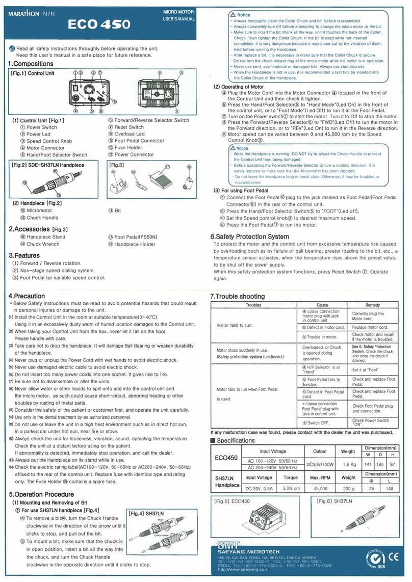
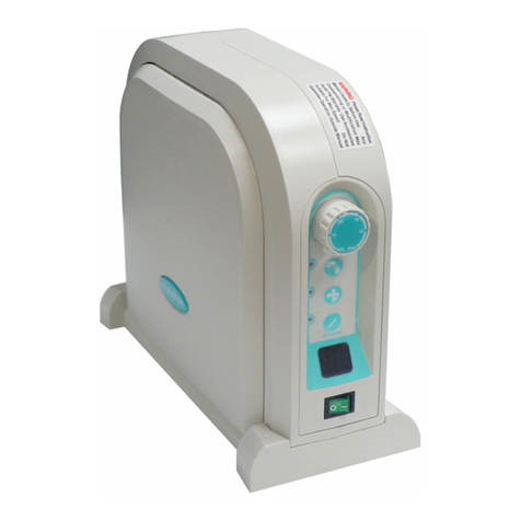
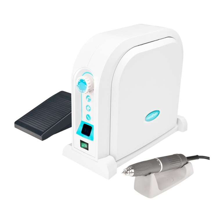
Saeyang Marathon Multi600 User manual

USER’S MANUAL
使用說明書
使用說明書
사용설명서


Read this User’s Manual thoroughly for safety before
preparing the unit for use.
機器を使う前、安全のため、この說明書をよくご覽になってく
ださい。
기기를 사용하시기 전에 안전을 위해 이 사용설명서를 잘 읽
어 보세요
ENG
JPN
CHN
KOR

Fig-1
Fig-2
Fig-3
ENG
Contents
1. Complete set
2. Electric power
3. Installation
4. Mounting & electric connection
5. Components
6. What to do before operation
7. How to operate
8. Care and maintenance
9. Technical data
1. Complete set
Make sure that the following
items(1.1~1.3) are included in your unit
package:
1.1 Desktop model(SDE-S60)[Fig. 1]
- Control unit(SDE-S60/L60)
- Control unit stand
- Motor handpiece(SDE-BH60)
- Motor handpiece stand
- Foot pedal(FS60)
1.2 Knee control model(SDE-L60)[Fig. 2]
- Control unit(SDE-S60/L60)
- Mounting bracket
- Motor handpiece(SDE-BH60)
- Motor handpiece stand
1.3 Tools [Fig. 3]
- Spanner
- Test bur

JPN
目次
1. 本體と部品
2. 主電源
3. 設置
4. 組立て 及び 接續
5. 各部位の名稱
6. 使用前の準備
7. 操作
8. 整備
9. 技術資料
1. 本體と部品
モデル別 構成品(1.1∼1.3)を確かめてくださ
い°
1.1 デスクトップ モデル(SDE-S60) 「第1圖」
- コントロ-ル ユニット (SDE-S60/L60)
- コントロ-ル ユニット スタンド
- ハンド ピ-ス (SDE-BH60)
- フット ペダル (FS 60)
1.2 膝 コントロ-ル モデル (SDE-L60)
「第2圖」
- コントロ-ル ユニット (SDE-S60/L60)
- 壁付着用 ブラケット
- バンド ピ-ス (SDE-BH60)
- ハンド ピ-ス スタンド
1.3 アクセサリ「第3圖」
- 分解用 工具
- テスト バ-(BUR)
KOR
CHN
1. 본체와 부속품
모델별 구성품(1.1~1.3)을 확인하여 주십시오.
1.1 데스크탑 모델(SDE-S60)[Fig. 1]
- 컨트롤 유닛(SDE-S60/L60)
- 컨트롤 유닛 스탠드
- 핸드피스(SDE-BH60)
- 핸드피스 스탠드
- 풋페달(FS60)
1.2 무릎 컨트롤 모델(SDE-L60)[Fig. 2]
- 컨트롤 유닛(SDE-S60/L60)
- 벽부착용 브래킷
- 핸드피스(SDE-BH60)
- 핸드피스 스탠드
1.3 액세서리[Fig. 3]
- 분해용 공구
- 테스트 버(bur)

Fig-4
Fig-5
ENG
2. Electric power
2.1 Check the electric rating
label(AC200~240V, 50/60Hz or
AC100~120V, 50/60Hz) affixed to the
rear of the unit.
2.2 Use only the fuse with allowable
electric voltage(2.0A 250V) for fuse
holder ⑫.
CAUTION
1. Never plug or unplug the power cord
with wet hands to avoid electric shock.
2. Be sure to use only the power earthed.
3. Installation
3.1 The SDE-S60 is a desktop model.
3.2 The SDE-L60 is a knee control model.
CAUTION
1. The control unit should rest on a flat,
steady surface.
2. Use the unit in locations that have
indoor temperature(0~40℃). Avoid
using the unit in an excessively dusty,
warm or humid location, due to electric
shock or damage to the unit.

JPN
2. 主電源
2.1 接續電源は本體の後面に付いているラベルに
許容電源(AC200∼240V, 50/60 Hz 或は
AC100∼120V, 50/60 Hz)を確かめた後,
認可する°
2.2 ヒュ-ズ ホ-ルだ⑫のヒュ-ズは許容電流
(2.0A 250V)の物を使用する°
ご注意
1. 濡れた手で電源コ-ドプラグを差し んだり,
引き拔かないこと°
感電のおそれがある°
2. 必ずア-スされている電源を使用すること°
3. 設置
3.1 デスクトップ(SDE-S60)のコントロ-ルユニ
ットは作業臺の上に取り付けて使用するこ
と°
3.2 膝 コントロ-ルモデル(SDE-L60)のコント
ロ-ルユニットは作業臺の下端壁面に膝の高
さを位置
に取りつけて使用すること°
ご注意
1. コントロ-ルユニットは被工作物からの妨害
のない平たい安定した場所に置いて使用する
こと°
2. コントロ-ルユニットは適當な室溫の範圍(0
∼40℃)內にて使用すること°
ほこりが多い所や高溫多濕な所に長時間使う
場合, 電氣の短絡 或は感電のおそれがあり,
なお機器の壽命を短縮させることにもなる°
KOR
CHN
2. 주전원
2.1 접속전원은 본체 후면에 부착되어있는 라벨의
허용되는 전원(AC200~240V, 50/60Hz 혹
은 AC100~120V, 50/60Hz)을 확인한 후
인가하여 주십시오.
2.2 휴즈홀더⑫의 휴즈는 허용전류(2.0A 250V)
의 것을 사용하여 주십시오.
주의
1. 젖은 손으로 전원 코드 플러그를 꽂거나 뽑지
마십시오. 감전의 위험이 있습니다.
2. 반드시 접지된 전원을 사용하십시오.
3. 설치
3.1 데스크탑 모델(SDE-S60)의 컨트롤 유닛은
작업대 위에 설치하여 사용하십시오.
3.2 무릎 컨트롤 모델(SDE-L60)의 컨트롤 유닛
은 작업대 하단 벽면 무릎 높이에 설치하여 사
용하십시오.
주의
1. 컨트롤 유닛은 피공작물의 방해를 받지 않으며
평평하고 안정된 장소에 두고 사용하십시오.
2. 컨트롤 유닛은 적절한 실내온도의 범위(0~40
℃)에서 사용하세요. 먼지가 많은 곳이나 고온
다습한 곳에서의 장시간 사용은 전기적인 숏트
나 감전의 위험이 있으며, 기기의 수명을 떨어
뜨립니다.

Fig-6
Fig-8
Fig-7
ENG
4. Mounting and electric connection
4.1 Desktop model(SDE-S60)
4.1.1 Tighten the bolts for control unit stand
⑭ on the bottom of control unit ① while
keeping knee control panel ⑧ pressed
fully[Fig. 6].
4.1.2 Plug motor cord into motor connector
⑩ located in the rear of the control unit
and then tighten plug nuts[Fig. 7].
4.1.3 Plug foot pedal cord ⑮ into foot pedal
connector ⑪ located in the rear of the
control unit[Fig. 7].
4.1.4 Plug power cord into power connector
⑬ in the rear of the control unit[Fig. 7].
CAUTION
1. After setting up the control unit stand,
make sure that the knee control pedal is
fully closed.
2. Make sure that the bolts for the control
unit stand are firmly tightened to set
the control unit in proper condition.
3. Make sure that all the cords are
connected safely and properly before
plugging the power cord.

JPN
4. 組立て 及び接續
4.1 デスクトップモデル(SDE-S60)
4.1.1 コントロ-ルユニットスタンド⑭は膝調整板
⑧を完全に押壓狀態にし, コントロ-ル ユニ
ット①の下端部に固定ボルとをしっかり締
め付けること°「第6圖」
4.1.2 モ-タコ-ド ⒗ プラグはコントロ-ルユニッ
トの裏面にあるモ-タコネックタ⑩に方向を
確かめて差し んだ後プラグナットを締め
付けること°「第7圖」
4.1.3
フットペタルコ-ド⑮プラグはコントロ-ルユ
ニットの裏面にあるフットペタルコネッタ⑪
に 方向を確かめた後しっかり差し ませる
4.1.4 電源コ-ド プラグはコントロ-ルユニッ
トの裏面にある電源コネックタ ⑬ にしっか
り差し ませる°「第7圖」
ご注意
1. コントロ-ルユニットスタンドを組立てた後,
膝調整板がしっかり閉じられているかどう
がを確かめること°
2. コントロ-ルユニットスタンドの固定ボルと
がコントロ-ルユニットとしっかり締め付け
られているかどうかを確かめること°
3. 電源コ-トプラグはすべてのコ-ドを接續させ
た後, 安全のチェックを行うこと°
KOR
CHN
4. 조립과 접속
4.1 데스크탑 모델(SDE-S60)
4.1.1 컨트롤 유닛 스탠드 ⑭ 는 무릎조정판 ⑧ 을
완전히 누른 상태에서 컨트롤 유닛 ① 하단부
에 고정용 볼트를 이용해 견고하게 체결하십
시오.[Fig. 6]
4.1.2 모터 코드 ⒗ 플러그는 컨트롤 유닛 뒷면 모
터 컨넥터 ⑩ 에 방향을 확인하여 삽입한 후
플러그 너트를 죄어 주십시오.[Fig. 7]
4.1.3 풋페달 코드 ⑮ 플러그는 컨트롤 유닛 뒷면 풋
페달 컨넥터 ⑪ 에 방향을 확인한 후 견고히
삽입하여 주십시오.[Fig. 7]
4.1.4 전원 코드 플러그는 컨트롤 유닛 뒷면의
전원 컨넥터 ⑬ 에 견고하게 삽입하여 주십시
오.[Fig. 7]
주의
1. 컨트롤 유닛 스탠드를 조립한 후 무릎조정판
이 완전히 닫혀져 있는지 확인하십시오.
2. 컨트롤 유닛 스탠드의 고정용 볼트가 컨트롤
유닛과 견고히 체결되어 있는지 확인하여 주
십시오.
3. 전원 코드 플러그는 모든 코드를 접속한 다음
안전을 확인한 후 접속하여 주십시오.

ENG
4.2 Knee control model(SDE-L60)
4.2.1 Set mounting bracket ⑨ to a proper
place for knee control under your
technical desk as shown in Fig. 9, using
bolts and screws.
The recommended height of the
mounting bracket from the bottom is:
1) 520~550mm for oriental people
2) 530~580mm for western people
4.2.2 As shown in Fig. 9, firmly mount the
control unit bracket in the proper
direction after checking their holes.
4.2.3 Plug motor cord into motor connector
⑩ in the rear of the control unit in the
proper direction, and then tighten the
plug nuts firmly[Fig. 10].
4.2.4 Plug power cord into power connector
⑬ located in the rear of the control
unit[Fig. 10].
CAUTION
1. While setting the mounting bracket,
special care should be taken for a bolt
or screw head not to be out of the
surface of the bracket.
Fig-9
Fig-10 Fig-11

JPN
4.2 膝コントロ-ルモデル(SDE-L60)
4.2.1 壁付着用ブラケット⑨は作業臺の下端部壁
面に圖示のごとく膝高あたりの所にボルと
或はスクリュを使って固く取り付けること°
「第9圖」
※床面から壁付着用ブラケットの高さ“h”は
1)東洋人の場合には 520 ∼ 550mm
2)西洋人の場合には 530 ∼ 580mm
4.2.2 コントロ-ルユニット①は取り付けられたブ
ラケットに圖示の方向に穴の位置を確かめ
た後, 搖れ動かないようにしっかりとりつけ
ること°「第9圖」
4.2.3 モ-タコ-ド ⒗ プラグはコントロ-ルユニッ
トの裏面にあるモ-タコネックタ⑩に方向を
確かめ差し んだ後プラグナットを締め付
けること°「第10圖」
4.2.4 電源コ-ド プラグはコントロ-ルユニッ
トの裏面にある電源コネックタ⑬にしっか
り差し ませること°「第10圖」
ご注意
1. 壁付着用ブラケットを取り付ける時に固定
ボルと 或はスクリュウの頭部がブラケット
面より突出しないよう注意すること°
KOR
CHN
4.2 무릎 컨트롤 모델(SDE-L60)
4.2.1 벽부착용 브래킷⑨은 작업대 하단부 벽면에
그림과 같이 무릎높이 적당한 곳에 볼트 혹은
스크류를 사용하여 견고하게 부착하여 주십시
오.[Fig. 9]
※
바닥에서부터 벽부착용 브래킷의 높이 ”h”는
1) 동양인의 경우에는 520~550mm
2) 서양인의 경우에는 530~580mm를
추천합니다.
4.2.2 컨트롤 유닛①은 부착된 브래킷에 그림과 같
은 방향으로 홀위치를 확인한 후 흔들림이 없
도록 견고히 부착하여 주십시오.[Fig. 9]
4.2.3 모터 코드 ⒗ 플러그는 컨트롤 유닛 뒷면 모
터 컨넥터⑩에 방향을 확인하여 삽입한 후
플러그 너트를 죄어 주십시오.[Fig. 10]
4.2.4 전원 코드 플러그는 컨트롤 유닛 뒷면의
전원 컨넥터⑬에 견고하게 삽입하여 주십시
오.[Fig. 10]
주의
1. 벽부착용 브래킷 부착 시에 고정용 볼트 혹은
스크류의 머리가 브래킷 면보다 돌출되지 않
게 주의하여 주십시오.

Fig-12
ENG
5. Components
① Control unit
② Speed control knob
③ Hand/foot selector switch
④ Forward/reverse selector switch
⑤ Motor switch
Auto cruise switch
⑥ Speed display
⑦ Power switch
⑧ Knee control panel
⑨ Mounting bracket
⑩ Motor connector
⑪ Foot pedal connector
⑫ Fuse holder
⑬ Power connector
⑭ Control unit stand
⑮ Foot pedal
⒃ Test bur
⒔ Chuck
⒕ Chuck handle
⒖ Motor
⒗ Motor cord
Handpiece stand
Power cord
Tools

JPN
5. 各部位の名稱
① コントロ-ル ユニット
② 回轉數 調整ハンドル
③ ハンド/フ-ト切換スイッチ
④ 正逆切換スイッチ
⑤ モ-タスイッチ/自動回轉スイッチ
⑥ 回轉數表示部
⑦ 電源スイッチ
⑧ 膝調整板
⑨ 壁付着用 ブラケット
⑩ モ-タコネックタ
⑪ フット ペダル
⑫ フュ-ズ ボルだ
⑬ 電源 コネックタ
⑭ コントロ-ルユニットスタンド
⑮ フットペダル
⒃ テスタバ-
⒔ チャック
⒕ チャック ハンドル
⒖モ-タ
⒗モ-タコ-ド
ハンドピ-ススタンド
電源コ-ド
分解工具
KOR
CHN
5. 각 부위의 명칭
① 컨트롤 유닛
② 회전수 조정손잡이
③ 핸드/풋 전환스위치
④ 정역 전환스위치
⑤ 모터스위치/
자동회전스위치
⑥ 회전수 표시부
⑦ 전원스위치
⑧ 무릎조정판
⑨ 벽부착용 브래킷
⑩ 모터 컨넥터
⑪ 풋페달 컨넥터
⑫휴즈홀더
⑬ 전원 컨넥터
⑭ 컨트롤 유닛 스탠드
⑮ 풋페달
⒃ 테스트 버
⒔척
⒕ 척 손잡이
⒖모터
⒗모터코드
핸드피스 스탠드
전원코드
분해공구

Fig-13
Fig-14 Fig-15
ENG
6. What to do before operation
6.1 Set power switch ⑦ to "0," OFF
position, whenever connecting the
motor handpiece and foot pedal[Fig.
13].
6.2 While the LED of hand/foot selector
switch ③ is off, the motor speed can be
controlled by speed control knob ②
within the limit of
1,000~50,000RPM[Fig. 13].
6.3 When the LED is turned on by pressing
hand/foot selector switch ③, it is
possible to control the speed, using
knee control panel ⑧ and foot pedal ⑮
[Fig. 13].
6.4 The orange-colored LED is turned on
by pressing auto cruise switch ⑤ while
knee control panel ⑧ or foot pedal ⑮ is
in use. When knee control panel ⑧
and foot pedal ⑮ remain at the same
position for 2 seconds, the mode keeps
running at the uniform speed. The auto
cruise mode can be released by
pressing again either knee control panel
⑧ or foot pedal ⑮[Fig. 13].
6.5 The motor speed can be controlled by
knee control panel ⑧ and foot pedal ⑮
within the limit set by speed control
knob ②.
6.6 When the LED of forward/reverse
selector switch ④ is off, the motor is
running counterclockwise[Fig. 13].
6.7 Test bur can be replaced by turning
chuck handle clockwise. After replacing
the test bur or a polishing point, the
chuck handle must be turned
counterclockwise to be securely
held[Fig. 14].

CAUTION
1. For 40,000RPM or more, it is required
to use the recommended bur only.
2. Always remove dirt before replacing a
test bur/polishing point.
3. After replacing a test but/polishing
point, it is necessary to make sure that
the chuck is securely held before
running the motor.
4. While the motor is running, DO NOT try
to adjust the chuck handle to prevent
the unit from being damaged.
5. When the motor handpiece is not in
use, it is recommended for a test
bur/polishing point to be kept inserted
into the motor handpiece.
6. Always put the motor handpiece on its
stand while in use. Special care must
be taken not to drop it on the floor.
JPN
6. 使用前の準備事項
6.1 ハンドピ-スとフット ペタルを接續する時に
はコントロ-ルユニットの電源スイッチ⑦を
“0”(OFF)に置きなさい°「第13圖」
6.2 ハンド/フット 切換スイッチ③のLEDが消燈
された時回轉數調整ハンドル②を使って
1,000∼50,000RPMまで速度の調整ができ
ます°「第13圖」
6.3 ハンド/フット 切換スイッチ③を押壓すれば
LEDが點燈され, 膝調整板⑧がフット ぺタル
⑮を使って速度の調整ができます°「第13圖」
6.4 膝調整板⑧或はフット ペタルを使用する時に
自動回轉スイッチ⑤を押壓すればオレンジ色
のLEDが點燈され, 同じ位置で2秒間留まる
場合“ピ-ピ-”音とともにモ-タを等速回轉しま
す°膝調整板 或はフットぺタルを再び踏むと
か自動回轉スイッチを押壓すれば自動回轉
モ-ドは 解除されます°「第13圖」
6.5 膝調整板⑧とフット ぺタル⑮の操作による
モ-タの回轉速度は回轉數調整ハンドル②に
よって 設定された回轉數に制限されます°
「第13圖」
6.6 正逆切換スイッチ④のLEDが消燈された時,
モ-タは反時計針方向に回轉します°
「第13圖」
6.7 テスタバ-⒃を取替えするためにはハンド
ピ-ス チャックハンドル⒕を時計針方向に
回しチャックを開きなさい°テスタバ-或はポ
リシング ポイントを取替えた後チャックハン
ドルを反時計針方向に回せばチャックが締ま
ります°「第14圖」
ご注意
1. 40,000RPM以上において使用する場合には
必ずバ-のメ-カ-または販賣者から許容され
たバ-に限って使用しなさい°
2. テスタバ-或はポリシングポイントを取換え
する時にはいつも異物質を取除きなさい°
3. テスタバ-或はポリシングポイントを取換え
した後にはチャックが完全に締まっているか
どうかを確かめた後モ-タを作動してくださ
い°
4. モ-タが作動中である時にはぜひともチャッ
クハンドルを回してはいけません°故障を起
こす原因になります°
5. 長い間ハンドピ-スを使わない場合にはテス
トバ-或はポリシングポイントを差し んで
ください°
6. 作業待ちの間ハンドピ-スはいつもスタンド
の上に置いてください「第15圖」特にハンド
ピ-スが衝擊を受けたり床に落とされた場合
直ちに故障を發生するおそれがあるため注意
を要します°

CHN

KOR
6. 사용 전 준비사항
6.1 핸드피스와 풋페달을 접속할 시에는 컨트롤 유
닛의 전원스위치⑦를“0”(OFF)에 두십시오.
[Fig. 13]
6.2 핸드/풋 전환스위치 ③ 의 LED가 소등되었을
때, 회전수 조정손잡이 ② 를 이용해 1,000~
50,000RPM까지 속도 조정이 가능합니
다.[Fig. 13]
6.3 핸드/풋 전환스위치 ③ 를 누르면 LED가 점등
되며, 무릎조정판 ⑧ 과 풋페달 ⑮ 을 이용해
속도 조정이 가능합니다.[Fig. 13]
6.4 무릎조정판 ⑧ 이나 풋페달 ⑮ 사용 시에 자동
회전스위치 ⑤ 를 누르면 오렌지색 LED가 점
등되며, 같은 위치에서 2초간 머무를 경우
“삐·삐”음과 함께 모터는 등속회전 합니다.
무릎조정판이나 풋페달을 다시 밟거나 자동회
전스위치를 누르면 자동회전모드는 해제됩니
다.[Fig. 13]
6.5 무릎조정판 ⑧ 과 풋페달 ⑮ 조작에 의한 모터
의 회전속도는 회전수 조정손잡이 ② 에 의해
설정된 회전수로 제한됩니다.[Fig. 13]
6.6 정역 전환스위치 ④ 의 LED가 소등되었을 때,
모터는 반시계방향으로 회전합니다.[Fig. 13]
6.7 테스트 버 ⒃ 를 교환하기 위해서는 핸드피스
척 손잡이 ⒕ 를 시계방향으로 돌려 척을 여
십시오. 테스트 버 혹은 폴리싱 포인트를 교환
한 후 척 손잡이를 반시계방향으로 돌리면 척
이 잠깁니다.[Fig. 14]
주의
1. 40,000RPM 이상에서 사용하실 경우에는 반
드시 버 제조자 또는 판매업자가 허용한 버만
을 사용하십시오.
2. 테스트 버 혹은 폴리싱 포인트 교환 시에는 항
상 이물질을 제거하십시오.
3. 테스트 버 혹은 폴리싱 포인트 교환 후에는 척
이 완전히 잠겨 있는지 확인한 후 모터를 작동
시키십시오.
4. 모터가 작동 중일 때에는 절대 척 손잡이를 조
작하지 마십시오. 고장의 가장 큰 원인이 됩니
다.
5. 장시간 핸드피스를 사용하지 않을 경우에는 테
스트 버 혹은 폴리싱 포인트를 삽입하여 주십
시오.
6. 작업 대기 중의 핸드피스는 항상 스탠드 위에
거취하여 주십시오.[Fig. 15] 특히, 핸드피스
가 충격을 받거나 바닥에 떨어질 경우 즉시 고
장이 발생할 수 있으므로 주의하여 주십시오.

Fig-16 Fig-17 Fig-18
ENG
7. How to operate
7.1 Procedures
a. Plug the power cord into an electric
outlet.
b. Set speed control knob ② to the slowest
position.
c. Turn on power switch ⑦.
d. Press motor switch ⑤ to run the motor.
e. Set speed control knob ② to the desired
speed.
f. Press hand/foot selector switch ③ if it is
necessary to control the motor speed,
using foot pedal ⑮ or knee control panel
⑧.
g. The motor stops by pressing again
motor switch ⑤.
CAUTION
1. Wear safety glasses and mask
whenever doing cutting or grinding
works.
2. Do not exceed the maximum operating
speed(50,000RPM) of the unit because
its operation at too high speed may
result in damage to the unit, as well as
personal injury.
3. Never try to touch the chuck handle
while the motor is in operation.
4. Special care must be taken not to drop
the motor handpiece or control unit on
the floor.
5. Before turning off the power switch, it is
surely required to make sure that the
motor has been stopped by pressing the
run switch.
6. Unplug the power cord when the unit is
not in use.
JPN
7. 操作
7.1 操作手順
a. 電源コ-ド プラグを電源コンセントに連
結します°
b. 回轉數調整ハンドル ② を最低の位置に置き
ます°
c. 電源スイッチ ⑦ をONします°
d. モ-タスイッチ⑤を押壓すればモ-タが回りま
す°
e. 回轉數調整ハンドル②を回し望むモ-タ回轉
數を設定しなさい°

f. フットペダル⑮または膝調整板⑧にて回轉數
を調整したい場合にはハンド/フット切換ス
イッチ③ を押壓後?使用しなさい°
g. モ-タを止めたい場合にはモ-タスイッチ⑤を
再び押壓しなさい°
ご注意
1. 切削或は硏磨作業を行う時には保護メガネと
マスクをいつも着用しなさい°
2. 最大回轉速度(50,000 RPM)にて長時間使
用したならばハンドピ-スやコントロ-ルユニ
ットの 壽命を短縮させます°
3. モ-タが作動中の時にはぜひともハンドピ-ス
チャックハンドルを動かしてはいけません°
4. 絶對にハンドピ-スやコントロ-ルユニットを
落とさないように心かけてください°
5. 電源スイッチをOFFしたい場合にはモ-タス
イッチを押壓し必ずモ-タが止っていること
を確かめた後?電源スイッチを操作しなさい°
6. ハンドピ-スを長時間使用しない場合には電
源コ-ドを引き拔いて置きなさい°
KOR
CHN
7. 조작
7.1 조작 순서
a. 전원 코드 플러그를 전원 콘센트에 연결
합니다.
b. 회전수 조정손잡이②를 최저 위치에 둡니다.
c. 전원스위치⑦를 켭니다.
d. 모터스위치⑤를 누르면 모터가 회전합니다.
e. 회전수 조정손잡이②를 돌려 원하는 모터 회전
수를 설정하십시오.
f. 풋페달⑮이나 무릎조정판⑧으로 회전수를 조
정하고자 할 경우에는 핸드/풋 전환스위치③를
누른 후 사용하십시오.
g. 모터를 정지시키고자 할 경우에는 모터스위치
⑤를 다시 누르십시오.
주의
1. 절삭이나 연마작업을 할 때에는 보호안경과 마
스크를 항상 착용하십시오.
2. 최대 회전속도(50,000RPM)에서의 장시간
사용은 핸드피스 및 컨트롤 유닛의 수명을 떨
어 뜨립니다.
3. 모터가 작동 중일 때에는 절대 핸드피스 척 손
잡이를 조작하지 마십시오.
4. 절대 핸드피스나 컨트롤 유닛을 떨어 뜨리지
마십시오.
5. 전원스위치를 끄고자 할 경우에는 모터스위치
를 눌러 반드시 모터가 정지한 것을 확인 한 후
전원스위치를 조작하십시오.
6. 핸드피스를 장시간 사용하지 않을 경우에는 전
원 코드를 뽑으십시오.

ENG
8. Care and maintenance
8.1 How to mount and dismount the collet
chuck
8.1.1 Turn the collet chuck counterclockwise
while opened to dismount. If the collet
chuck can not be turned manually, use
tools to dismount it[Fig. 19].
8.1.2 To mount the collet chuck, it is required
to first open the chuck handle and then
insert the collet chuck and test bur.
Then, fully turn the collet chuck
clockwise with fingers and then turn a
fifth counterclockwise again available
for the test bur to be released.
8.2 How to disassemble the chuck handle
and motor
8.2.1 The chuck handle and motor are
disassembled by continuously turning
the chuck handle counterclockwise
[Fig. 20].
8.3 How to disassemble the motor and its
cord
8.3.1 The motor cord is disassembled by
continuously turning the motor
counterclockwise[Fig. 21].
CAUTION
1. Thoroughly clean the collet chuck and
test bur before reassembled. It is
recommended to clean them once a
week, for safety.
2. Special care must be taken for the
chuck handle and motor to be free
from and dirt during disassembly.
3. Only the skilled engineer is authorized
to disassemble the spindle and motor,
in order to avoid any damage to
them[Fig. 20][Fig. 21].
Fig-19
Fig-20 Fig-21
Other manuals for Marathon Multi600
1
Table of contents
Languages:
Other Saeyang Dental Equipment manuals
Popular Dental Equipment manuals by other brands

Den-Mat
Den-Mat PSP Pro-Select Platinum Operation and instruction manual

Amanngirrbach
Amanngirrbach smartwax duo operating instructions

3Disc
3Disc FireCR Dental user manual

KaVo
KaVo EWL 5837 Operating instruction

DTE
DTE Lux E instruction manual

VERDER
VERDER Carbolite Gero CDF 15/1b Installation, operation & maintenance instructions