Safari Snorkel SS385HF User manual

SS385HF
LAND ROVER DISCOVERY 3
2.7L TDV6 SE
27t06t06
ITEM DESCRIPTION QTY PART NO
1BODY - SNORKEL 1830-1 33-800
231/d' AIR RAM ASSEMBLY 1000-135-650
3BRACKET . UPPER MOUNTING 1830-032-800
4BOLT - HEX - 6mm x 1.0 x '14mm (SEMS) 3000-002-1 00
5POP RIVET - 4.8mm r 14mm I000-958-350
6STUD - S/S - 8mm x 1.25 x 25mm O/L 2000-1 1 0
7WASHER-BODY-8mmx30mm 2000-311
8NUT-NYLOC-8mmx1,25mm 2000-205
ISTUD - S/S 6mm x 1.0 x 25mm OL J000-1 08
10 WASHER-BODY-6mmx20mm 3000-321
11 NUT-NYLOC-6mmx1.Omm 3000-204
12 DUCT - CONNECTING 1830-023-800
13 CUFFED HOSE - 82mm lD x 750mm 1000-887-075
14 CLAMP HOSE - 80/100mm 2'fu0-gog
15 SEAL _ FOAM 1830-410-800
16 TEMPLATE _ GUARD 1830-017-800
17 TEMPLATE - lNNffiR GUARD 1830-217-800
18 TEMPLATE _ MOUNTING BRACKET 1830-217-825
19 TEMPLATE -'A' PILLAR TRIM 1830-217-850
20 HOSE - CLAMP - SIZE 56 (BLACK) 1000-914/B
Manufactured by Safari Automotive Technologies Pty Ltd
73 Merrindale Drivä, South Croydon Victoria 3.136 Australia Te!; +61 3 9761 7244 Fax= +61 3 9761 7665
www.saf arisnorkel.com
ABN 88 071 262756
INST'qLL!-aTIC}N GUIOE - SFIFf:Ir*I SSSEISHF Pla€,E ' i gF 6

.....x*l+r:t§tlirL:iii.rr:''i1§t...a,a:i:-., -
?:ä:lr$ '-' FAM SS385HF
LAND ROVER DISCOVERY 3
2,7L TDV6 SE
Fitment to: Right hand side
Fitting time: Approximately 180 minutes
Special Tools: Air hacksaw
Step drill
Sikaflex 227 adhesive sealant
Smm Specialist drill bit for hard steel
Pop rivet gun
Prior to commencing the installation. it is the installer's responsibility to
verify that all components and particularly the template (ltem '16) are correct.
-= -r= - = - -r', - =--- -= -= r'. -
Ä-^^
-A-:ea-=-=s--:-.
- Rigl'rt haric Lv-eel arcn 'er
Tape the template onto the guard
after aligning the top edge of the
template along the lower crease
and the rear edge of the guard.
using the two cut-outs of the
template as a gu oe.
. -^ ; j= - -f ne^. -a'( a lOf t^e
v ! . e Yv
rg e ocs t o.s ar"rc remove the
*.".
Drill a pilot hole for each marked
hole positions.
Using the step drill, drill the 2 lower
and the top centre holes to 14mm.
Drill the 2 fronl holes to 16mm.
Deburr and paint holes.
:-:'a:::i servrce manual.
- A r ntake grille and air ducting
- A' pillar trim
§ryeäry
I.ff
3Drill 14mm Diameter Holes Drill 'l6mm Diameter Holes
INST!"tt--Lt:1Tt§§r GLJ!ilE qHFl:lt?t SSSBSHF PrqGE - a [fF 6

6
Tape the inner guard template
(ltem No. 17) into position, aligning
the template with the standard air
intake hole.
Using a felt tip pen, mark the
section of panel that is required to
be removed.
Remove the template and with an
air hacksaw, cut away the marked
section of inner guard panel.
Fold down any sharp edges,
deburr and paint all sudaces.
-:ce :'9 -cL'ting bracket
-.=-= ='.= :=^. \c.'1Bi in:c
E,:s::- a 3- -Et^e temc ate -c
- -=> - =
-^^ ^j +- n ^
Using a fe{t tip pen" rnant< all
mounting bracket hole positions
and remove template. Using a
specialist drill bit for hard steel at
the recommended drill speed, drill
the 5 marked hole positions to
5mm diameter.
Apply Sikaflex adhesive sealant to
the upper mounting bracket
surface.
Apply Sikaflex adhesive sealant to
the underside of the pop-rivets
(ltem No. 5) and secure the
mounting bracket to the 'A' pillar.
r Apply Sealant and
lnstall A-Pillar Bracket
Fold sharp edges down
INSTTqLLF}TION GLJIDE . g'qF'qI?I §§3E3HF F3rqGE - 3 C]F 5

Tape the 'A' pillar trim template into
position on the underside of the 'A'
pillar plastic trim (note: cut away
the foam edging from the plastic
trim to insert the template).
Mark the 2 hole positions on the 'A'
pillar plastic trim and remove the
template.
Drill the 2 marked hole positions to
6mm and mark a straight line either
side of the holes. Using the air
hacksaw, cut the required slot in
the 'A' pillar plastic trim. Note: cut
'lhe outer side of the trim first then
:-e '^er side to prevent the trirn
'-:- :"a:k,ng. Using a f ile. smco:A
lf required, Remove 'A' pillar trim
and file the slot larger where need
tc achieve clearance.
lnstall the cuifed hose lhro-c^ r'e
agin ^c e ^:^e g-"'i.'a..a: -g:'e
:--eJ'cse ,','- s:'eeo ^g i'rc-3^
:-3 ^:e'^a ca\'ry,. Feec the currfeo
'ose 'cht up io the hole in the
^ner guard.
Position the hose clamp onto the
end of the cuffed hose, install the
connecting duct into the cuffed
hose, with the connecting duct and
cuffed hose correctly positioned,
fasten the hose clamp.
lnstall A-Pillar Trim
lnsert Cuffed Hose
t Align Template
Hose Clamp lnstall Air Cleaner Duct
A-Pillar Trim
I
Drill
iN§TfqLi-l.q'flsN §i-JtäH §r;{Fiqrci §§§*sHtr $}iä§B * 4 §l§ tä

10 Hose Clar;
{
Drill the 3 connecting duct
mounting hole Positions to 5mm
and secure the connecting duct to
the inner guard Panel using PoP
rivets (ltem no.5).
lnstall the 3 x 6mm studs and 2 x
3-- studs into the snorkel bodY
-se1s Dcsition the hose cla-c
= ^ -ea hose and aa'?'-
- -- ! -r
-::a .-3 s-:'<er bodY on:c:-3
^ .f3 C^^/{^ ^^^
--1 - v _ - J
. F.Ä.F:
'r =: - -= -'-.' -- ---''
=-^ .--<_=-
--: - - =- - =-- -
the sncrrte c33r :3 3-a'3 a^3
upper mounting bracket using
necessary hardware. With the
cuffed hose correctlY Positioned
onto the snorkel bodY snout, fasten
the hose clamP.
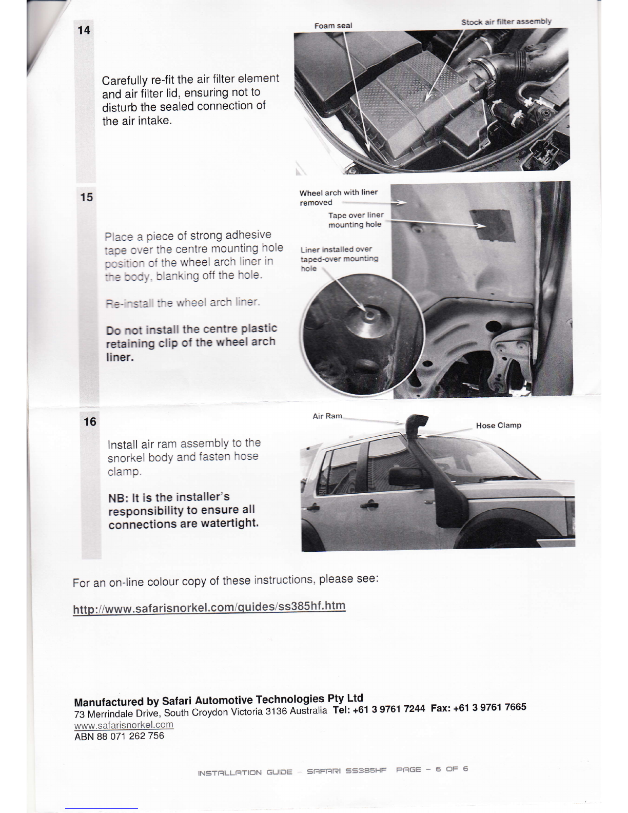
Remove the self-adhesive backing
f rom the foam seal (ltem No. 15)
and secure to the connecting duct.
Apply a liberal amount of Sikaf lex
adhesive sealant to the inside of
the connecting duct and around the
intake snout and f lange of the air
filter housing, to ensure a
watertight connection is achieved.
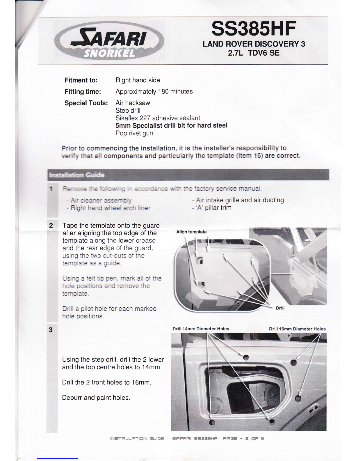
Carefully re-install the air filter
housing into position, ensuring all
surfaces seal together correctly.
llcse ClamP with head
facing wheel well Cuffed Hose
11 Sno-kel &oc-'
\{,
13 APPIY Sealant
".. around edge
Drill & Pop-Rivet
/
lg
12 With the snorker body correctry sec-.eo to the guard and upper mounting bracket. check
the clearance o, l-e s^c.<e cct le a:rve to thä bonnet rn the open and closed oositrcn 4
,eC-'33 re-3 3^:.e SrSr(e bOJl'O':'e guard tO aChieve adeCuate clearalCe
Peel off adhesive
backing and
place over
- duct
li'{§T'Sq [*!-l--{T iÜ1",} {§Llt*§: §ft§{El?i §S§§§!{!* pfiGH * ä ils ffi

Stock air fitter assembtY
15
Carefully re-fit the air filter element
and air filter lid, ensuring not to
disturb the sealed connection of
the air intake.
Place a piece of strong adhesive
lape over the centre mounting hole
c,ss tion of the wheel arch Iiner in
:re ccdy. blanking off the hole.
=e- -s:a ::e wheel arch I ner.
Do not install the centre Plastic
retaining cliP of the wheel arch
liner.
Wheel arch with liner
removed
TaPe over liner
mounting hole
Liner installed orer
tapedover mounting
hote
16
lnstall air ram assembly to the
snorkel bodY and fasten hose
clamP.
NB: lt is the installer's
responsibilitY to ensure all
con nections are watertight.
For an on-line colour copy of these instructions, please see:
ManufacturedbySafariAutomotiveTechnologiesPty.Ltd
73 Merrindale Drive, souirr croyoon victoria 3'13G Aus'iralia täl: +61 3 9761 7244 Fax: +61 3 9761 7665
www. saf arisnorkel.com
ABN 88 071 262756
IN5T!:ILLFITIC]N GUIDE - grlFF|rd! S53A5HF PI=IGE * 5 ÜF 6
Table of contents
Other Safari Snorkel Automobile Accessories manuals