manuals.online logo
Brands
  1. Home
  2. •
  3. Brands
  4. •
  5. Safe Fleet
  6. •
  7. Digital Camera
  8. •
  9. Safe Fleet HD2Q Series User manual

Safe Fleet HD2Q Series User manual

© Safe Fleet | 2020 | All rights reserved | Part #: 700-1207 R2
HD2Q Series Dome Camera
Quick Installation Guide
2002/96/EC (WEEE directive): This product cannot be disposed of as unsorted municipal waste
in the European Union. For proper recycling, return the product to your local supplier upon the
purchase of equivalent new equipment, or dispose of it at designated collection points, for more
information, see www.recyclethis.info.
2006/66/EC (battery directive): This product does not contain batteries.
Contact Safe Fleet Tech Support
• Phone: 1.844.899.7366
• Email: PTsupport@safeeet.net
Warranty
For full warranty information, visit:
• www.seon.com/documents/Seon-Warranty.pdf
Service & Support
If your HD2Q camera is to be returned for service, please contact the Safe Fleet Technical Support team,
provide the model and/or serial# of your unit, and ask for a Return Merchandise Authorization (RMA) number.
An RMA# allows the support team to better track your product when it comes in for service. Please show the
RMA# on the outside of the package.
ANY PRODUCT SENT WITHOUT AN RMA# MAY BE REFUSED!
Documentation
Additional copies of this guide along with other documentation can be found on the Safe Fleet Community
(https://community.safeeet.net).
Product Overview
This quick installation guide applies to the following camera models:
HD2QxxAI, HD2QxxAI20, HD2QxxAI50, HD2QxxAI75
The HD2Q camera with IR is designed for interior use only.
The camera can be installed with or without an angle-mount post.
This guide covers installation without the angle-mount post. For specic
instructions on mounting the HD2Q with the angle-mount post, see the
Dome Camera Mounting Posts Installation Instruction Sheet (part # 700-0188).
Recorder Compatibility
The HD2Q camera is compatible with the following recorders:
DH4C DVR, TH6 DVR, TH8 DVR, NH16 Hybrid NVR
Installation Kit Contents
• 1 HD2Q camera, including dome (dome part # 050-1044)
• 1 T10 security tool (part # 645-0008)
• 2 #8 screws (1” length, self-drilling Phillips, part # 600-1026)
• 1 mounting template (part # 700-1208)
 IMPORTANT: Camera Harness Cable Compatibility
This camera requires a special Analog High Denition (AHD) camera harness - as indicated by a blue
band in front of the connectors. The AHD harness is not included with the camera kit. If you require
an AHD harness, please contact our customer service department to place an order.
Step 1: Choose Camera Location
When choosing a camera mounting location, consider the desired eld of view, area of focus, and camera
assembly orientation.
1. Determine a location for mounting the camera:
a. Choose a solid surface to minimize vibration
b. Choose a location away from access panels, hatches, or doors which may block the camera view
c. Choose a location away from heat sources
d. Cameras are usually installed with the cabling running inside the wall panels.
2. Use the supplied mounting template to mark the cable hole (0.83”/21 mm) and screw holes (0.16”/4mm).
3. Use a step-bit to drill the cable hole.
Specications
Power Consumption 1.2 W (IR Off); 2.2 W (IR on)
Operating Voltage Range 8 to 14 VDC (powered by DVR)
Operating Temperature Range -4 to 122ºF (-20 to 50ºC)
Resolution 1920 * 1080p @30fps
Infrared LED Lamps 8 LEDs (5mm)
Minimum Illumination Color: 0.1 lux (F2.0)
B&W, IR LED on: 0 lux
Enclosure Size Diameter : 4.13” (105 mm)
Height: 2.79” (71 mm)
Enclosure Material Solid aluminum alloy
Rated IP54
Dome Impact-resistant polycarbonate, anti-glare, scratch-resistant hard
coating, UV protected
Camera Pigtail Connector Length 12” (30 cm)
Weight Camera only: 0.76 lbs. (0.34 kg)
Packaged: 1.06 lbs. (0.48 kg)
Fold Here
Step 2: Remove Camera Dome
1. Using the security key supplied with the camera, loosen the captive screws on the housing.
2. Lift the housing off the base.
Step 3: Connect Camera to Recorder
1. Connect the pigtail to the camera harness through the panel cable hole.
Important: ensure the camera harness cable has a blue band in front of the connectors, indicating it is
AHD-compatible.
2. Connect the camera harness 2x3 Microt connector to the recorder.
CAUTION: Camera circuit board and wiring
While installing the camera, do not impact the printed
circuit board or wiring inside the camera with screws or
screwdriver bits: damage to the camera can result.
Use the two #8 x 1” (25.4mm) self-drilling mounting screws
supplied with the camera to attach the camera to the vehicle.
Step 5: Aim the Camera
1. With a monitor connected to the recorder, power up the
system. The monitor should display multiple camera views
once the recorder is powered up.
2. Double-click a camera tile image to display it in full-screen
mode.
3. Aim the camera by tilting*, panning, and rotating as required.
* Loosen the two Phillips head tilt adjustment screws (one
on each side of the gimbal), adjust tilt as required, then re-
tighten the screws.
1
2
To video recorder
Step 7: Conguration Settings for Forward-facing Applications
For improved image quality in forward-facing camera applications (through the windshield) we recommend the
following procedure to disable infrared (IR) LEDs:
1. Right-click a recorder camera view to open the on-screen display.
2. Click Conguration.
3. Navigate to the Control over Coax (CoC) settings:
• If connected to a TH6 recorder:
 Record  Camera  Camera Advanced
• If connected to a TH8 or NH16 recorder:
 Record  Camera  Analog  CoC Cam Control
4. Click the tab corresponding to the recorder port number
connected to the HD2Q camera.
5. Click Set to display the SETUP menu.
6. Click twice to highlight FUNC.
7. Click Set to open the FUNC menu.
8. Click Set (again) open the DAY NIGHT menu.
9. Click six times to highlight IR LED.
10. Click to toggle the IR LED setting OFF.
11. Click to highlight RETURN.
12. Click Set to return to the FUNC menu.
13. Click twice to highlight RETURN.
14. Click Set to re-display the SETUP menu.
15. Click twice to highlight EXIT.
16. Click Set to open the EXIT menu.
17. Click to highlight SAVE AND EXIT.
18. Click Set to save settings.
The CoC menus close in a few seconds.
Step 6: Replace Camera Dome
1. Fit the dome onto the base.
Ensure the notches on the edge of the dome and the camera
base are aligned before tightening the security screws.
2. Ensure the rubber IR boot around the camera lens is rmly
pressed against the inside of the dome.
3. Use the security key to tighten the captive screws.
Routine Maintenance
Most liquid cleaners or grati gel can be used to clean your camera enclosure. Do not use abrasive cleaners
that can scratch the window and reduce visibility of the camera.
Replacing Damaged Dome Lid
If the dome bubble becomes scratched, cracked, or broken, please contact Safe Fleet Support to purchase a
replacement.
To remove and replace the housing, follow the procedures in "Step 2: Remove Camera Dome" and "Step 6:
Replace Camera Dome" on page 2.
Step 4: Install the Camera
#8 x 1” self-drilling
mounting screws
Alignment
notches
Pan
Tilt
Tilt adjustment
screw
Rotate
Recorder camera ports
CoC menu
controls
CoC menu

Other Safe Fleet Digital Camera manuals

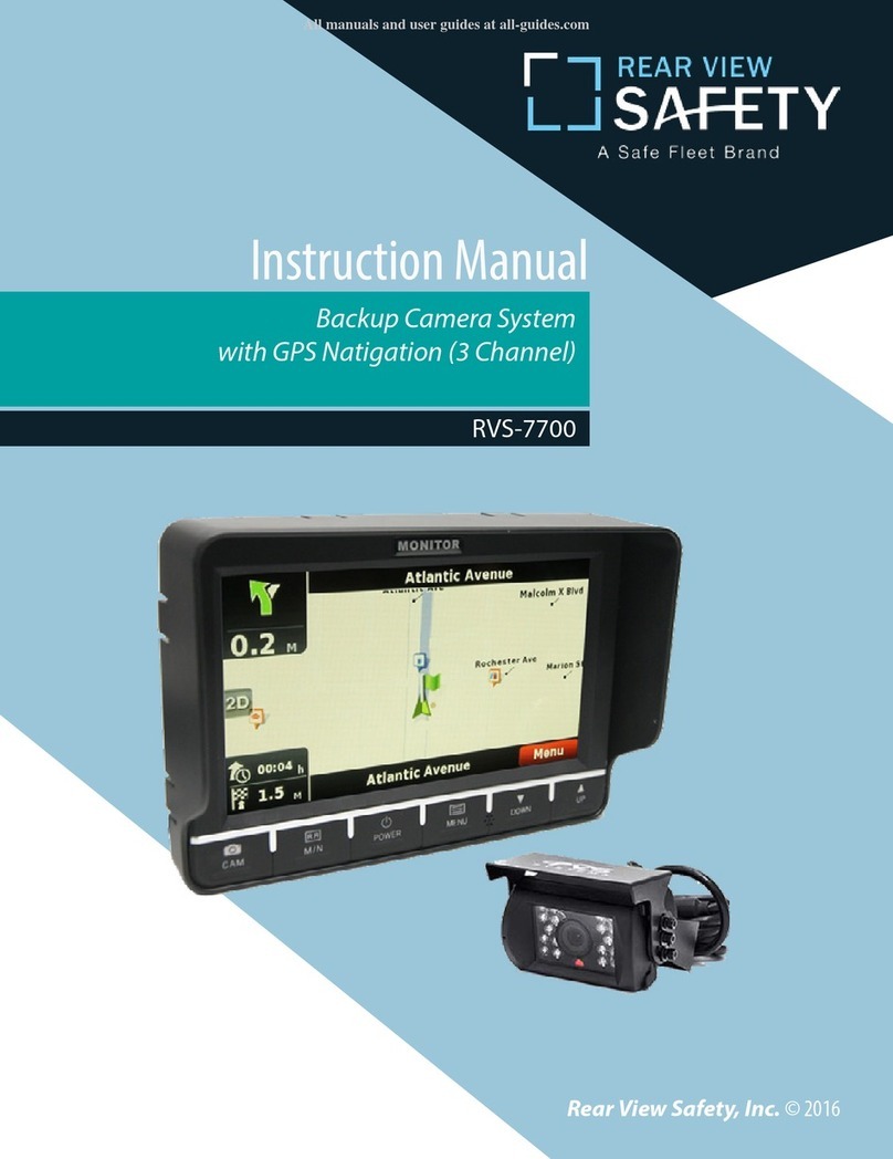
Safe Fleet REAR VIEW SAFETY RVS-7700 User manual

Safe Fleet

Safe Fleet REAR VIEW SAFETY RVS-7700 User manual

Safe Fleet RVS SimpleSight RVS-155W-HD User manual

Safe Fleet

Safe Fleet RVS SimpleSight RVS-155W-HD User manual

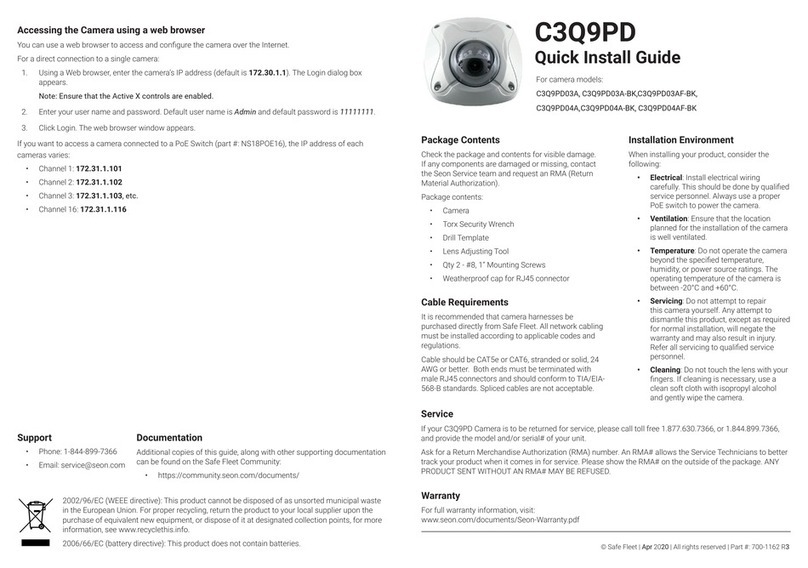
Safe Fleet C3Q9PD User manual

Safe Fleet

Safe Fleet C3Q9PD User manual

Safe Fleet SEON HD3W User manual

Safe Fleet

Safe Fleet SEON HD3W User manual

Safe Fleet Rear view safety RVS-772718 User manual

Safe Fleet

Safe Fleet Rear view safety RVS-772718 User manual

Safe Fleet MVC-9830 User manual

Safe Fleet

Safe Fleet MVC-9830 User manual

Safe Fleet SEON HD1W User manual

Safe Fleet

Safe Fleet SEON HD1W User manual

Safe Fleet SEON CA10 User manual

Safe Fleet

Safe Fleet SEON CA10 User manual

Safe Fleet RVS-082587 User manual

Safe Fleet

Safe Fleet RVS-082587 User manual

Safe Fleet RVS-651153 User manual

Safe Fleet

Safe Fleet RVS-651153 User manual

Safe Fleet C3W9PD03E User manual

Safe Fleet

Safe Fleet C3W9PD03E User manual

Popular Digital Camera manuals by other brands

Prosilica GC1380H user manual

Prosilica

Prosilica GC1380H user manual

Spycentre Security 2007 manual

Spycentre Security

Spycentre Security 2007 manual

Kodak RETINA IIIC manual

Kodak

Kodak RETINA IIIC manual

Olympus VG-110/D-700 instruction manual

Olympus

Olympus VG-110/D-700 instruction manual

Sony Cyber-shot DSC-H400 instruction manual

Sony

Sony Cyber-shot DSC-H400 instruction manual

Panasonic lumix DC-ZS70 Basic owner's manual

Panasonic

Panasonic lumix DC-ZS70 Basic owner's manual

Kodak Camera quick start

Kodak

Kodak Camera quick start

Olympus C-520 Advanced manual

Olympus

Olympus C-520 Advanced manual

Canon EOS Rebel T3 Basic instruction manual

Canon

Canon EOS Rebel T3 Basic instruction manual

AquaPix W5012 Splash manual

AquaPix

AquaPix W5012 Splash manual

UMAX Technologies C3 manual

UMAX Technologies

UMAX Technologies C3 manual

Leica D-LUX 6 instructions

Leica

Leica D-LUX 6 instructions

Hama 00176566 operating instructions

Hama

Hama 00176566 operating instructions

Casio Exilim EX-Z4U Function guide

Casio

Casio Exilim EX-Z4U Function guide

Philips SPC 300NC Instructions for use

Philips

Philips SPC 300NC Instructions for use

Odys Slim5Z user manual

Odys

Odys Slim5Z user manual

Casio EExilim X-FH25 user guide

Casio

Casio EExilim X-FH25 user guide

Canon 8406B001 user guide

Canon

Canon 8406B001 user guide

manuals.online logo
manuals.online logoBrands
  • About & Mission
  • Contact us
  • Privacy Policy
  • Terms and Conditions

Copyright 2025 Manuals.Online. All Rights Reserved.