manuals.online logo
Brands
  1. Home
  2. •
  3. Brands
  4. •
  5. Safe Fleet
  6. •
  7. Digital Camera
  8. •
  9. Safe Fleet SEON HD1W User manual

Safe Fleet SEON HD1W User manual

Other Safe Fleet Digital Camera manuals

Safe Fleet RVS SimpleSight RVS-155W-HD User manual

Safe Fleet

Safe Fleet RVS SimpleSight RVS-155W-HD User manual

Safe Fleet RVS-082587 User manual

Safe Fleet

Safe Fleet RVS-082587 User manual

Safe Fleet MVC-9830 User manual

Safe Fleet

Safe Fleet MVC-9830 User manual

Safe Fleet REAR VIEW SAFETY RVS-7700 User manual

Safe Fleet

Safe Fleet REAR VIEW SAFETY RVS-7700 User manual

Safe Fleet C3Q9PD User manual

Safe Fleet

Safe Fleet C3Q9PD User manual

Safe Fleet HD2Q Series User manual

Safe Fleet

Safe Fleet HD2Q Series User manual

Safe Fleet SEON HD3W User manual

Safe Fleet

Safe Fleet SEON HD3W User manual

Safe Fleet Rear view safety RVS-772718 User manual

Safe Fleet

Safe Fleet Rear view safety RVS-772718 User manual

Safe Fleet RVS-651153 User manual

Safe Fleet

Safe Fleet RVS-651153 User manual

Safe Fleet C3W9PD03E User manual

Safe Fleet

Safe Fleet C3W9PD03E User manual

Safe Fleet SEON CA10 User manual

Safe Fleet

Safe Fleet SEON CA10 User manual

Popular Digital Camera manuals by other brands

Canon WP-DC35 user guide

Canon

Canon WP-DC35 user guide

Xiaomi 70mai Dash Cam Lite user manual

Xiaomi

Xiaomi 70mai Dash Cam Lite user manual

Samsung PL70 Quick start manual

Samsung

Samsung PL70 Quick start manual

GE E1680W user manual

GE

GE E1680W user manual

Canon EOS 1200D instruction manual

Canon

Canon EOS 1200D instruction manual

Tevion MD 86497 user guide

Tevion

Tevion MD 86497 user guide

Exakta VX Features

Exakta

Exakta VX Features

Kodak Digital Science DC120 user guide

Kodak

Kodak Digital Science DC120 user guide

Nikon FM3A Specifications

Nikon

Nikon FM3A Specifications

Vectra Fitness H1 Quick reference guide

Vectra Fitness

Vectra Fitness H1 Quick reference guide

Nikon COOLPIX 775 quick start guide

Nikon

Nikon COOLPIX 775 quick start guide

Olympus IR 500 - 4MP Digital Solutions Camera Manuel de Référence

Olympus

Olympus IR 500 - 4MP Digital Solutions Camera Manuel de Référence

Samsung EC-L100ZBBA brochure

Samsung

Samsung EC-L100ZBBA brochure

FujiFilm FINEPIX BL01124-201 owner's manual

FujiFilm

FujiFilm FINEPIX BL01124-201 owner's manual

Panasonic DMC-L10KPP Service manual

Panasonic

Panasonic DMC-L10KPP Service manual

Hyundai Electric HYU-CC-CHBF12001 Quick installation guide

Hyundai Electric

Hyundai Electric HYU-CC-CHBF12001 Quick installation guide

Sony DSC-WX80 specification

Sony

Sony DSC-WX80 specification

Nikon Nuvis S - Point & Shoot instruction manual

Nikon

Nikon Nuvis S - Point & Shoot instruction manual

manuals.online logo
manuals.online logoBrands
  • About & Mission
  • Contact us
  • Privacy Policy
  • Terms and Conditions

Copyright 2025 Manuals.Online. All Rights Reserved.

HD1W Wedge Camera
Quick Installation Guide
© Seon Design Inc. | January 2017 | All rights reserved.
www.seon.com Part Number: 700-1085 R1
Installation Kit Contents
• 1 HD1W wedge camera
• 3 #10 3/4” Phillips screws
• 1 security key
• 1 Quick Installation Guide
• 1 Drilling template
1. Choose Camera Location
1. Determine the location for mounting the camera. Select a flat
location to minimize possible moisture leakage into the vehicle.
Cameras must be installed with the cabling running inside the wall
panels.
2. Use the supplied drilling guide template to mark the cable (7/8”)
and screw (5/32”) holes on the panel.
3. Use a step-bit to drill the cable hole, and regular bits for the screw
holes.
2. Connect the Camera
1. Connect the camera cable to the extension cable through the
panel cable hole. See Figure 1.
Important: ensure the extension cable has a blue band in front of
the connectors, indicating it is AHD (Analog High Definition)-com-
patible.
2. Connect the extension cable’s 2×3 Micro-Fit connector into a
digital video recorder (DVR).
3. Open the Camera
1. Using the security key supplied with the camera, loosen the four
captive screws on the housing. See Figure 2.
2. Lift the housing off of the base.
4. Install the Camera
Use the three #10×3/4" mounting screws supplied with the camera to
attach the camera to a wall or ceiling. See Figure 3.
The mounting gaskets on the camera base seal the screw and cable
holes when mounted on a flat surface.
5. View Camera Output
1. Power on the DVR and camera.
2. Connect the supplied local video out adapter cable’s 3.5mm audio
plug to the camera’s Local Video Out socket. See the image in
section 3.
3. Connect the local video out cable’s RCA end to a video monitor to
see the camera’s line of view while adjusting the camera’s rotation,
pan, and tilt positions.
WARNING: Cable Compatibility
This camera requires a special Analog High Definition (AHD) cable - as
indicated by a blue band in front of the connectors. Note that a
standard cable may appear to work on a small analog screen, but the
image will be significantly degraded during subsequent playback.
INSTALL TIP: Seal the camera mounting holes
For outdoor installations, if a flat surface is not available, carefully seal
the mounting holes under the base of the camera after installation. Do
NOT apply silicone or other sealants around the base of the camera.
*700-1085*
Figure 1
CAUTION: Housing can scratch vehicle
When the camera cover is open, take care to ensure it does not flop
against the vehicle surface. Damage to paint can occur.
INSTALL TIP: Camera PCB and Wiring
While installing the camera, do not impact the printed circuit board or
wiring inside the camera with screws or screwdriver bits.
Damage to the camera can occur.
INSTALL TIP: Allow Camera Ventilation
The camera is designed to vent for proper operation. Do NOT apply
silicone or other sealants around the base of the camera.
Figure 2
Camera housing
Captive housing
screws
LED and Ground
connection wires
Camera gimbal
Menu Button
Local Video Out
Base
Figure 3
Mounting gasket
Base
(Do not
apply
sealant
around
base)
#10x3/4”
mounting
screws
6. Aim the Camera
To get the required video image, adjust the camera‘s rotation, pan, and
tilt settings using the adjustment controls shown in Figure 4 and
described in the following steps:
1. Rotation: depending on how the camera is mounted, rotate the
camera lens so the video appears upright on the video monitor.
2. Pan: grip the camera pan adjustment U-Bracket sides and twist it
to find the required view.
3. Tilt: loosen the tilt adjustment screws on the U Bracket until the
camera can tilt. Tighten the tilt screws after adjustments are
complete. Do not adjust tilt after tightening screws.
7. Configuration Settings
1. In the camera, press the menu button to display the configuration
menu on the monitor.
2. Toggle the button up or down to select from BACKLIGHT or EXT
LED options, or to SAVE and EXIT.
3. With an option selected, toggle the button left or right to select sub
menu options.
4. Toggle up or down to exit the option and select SAVE and EXIT.
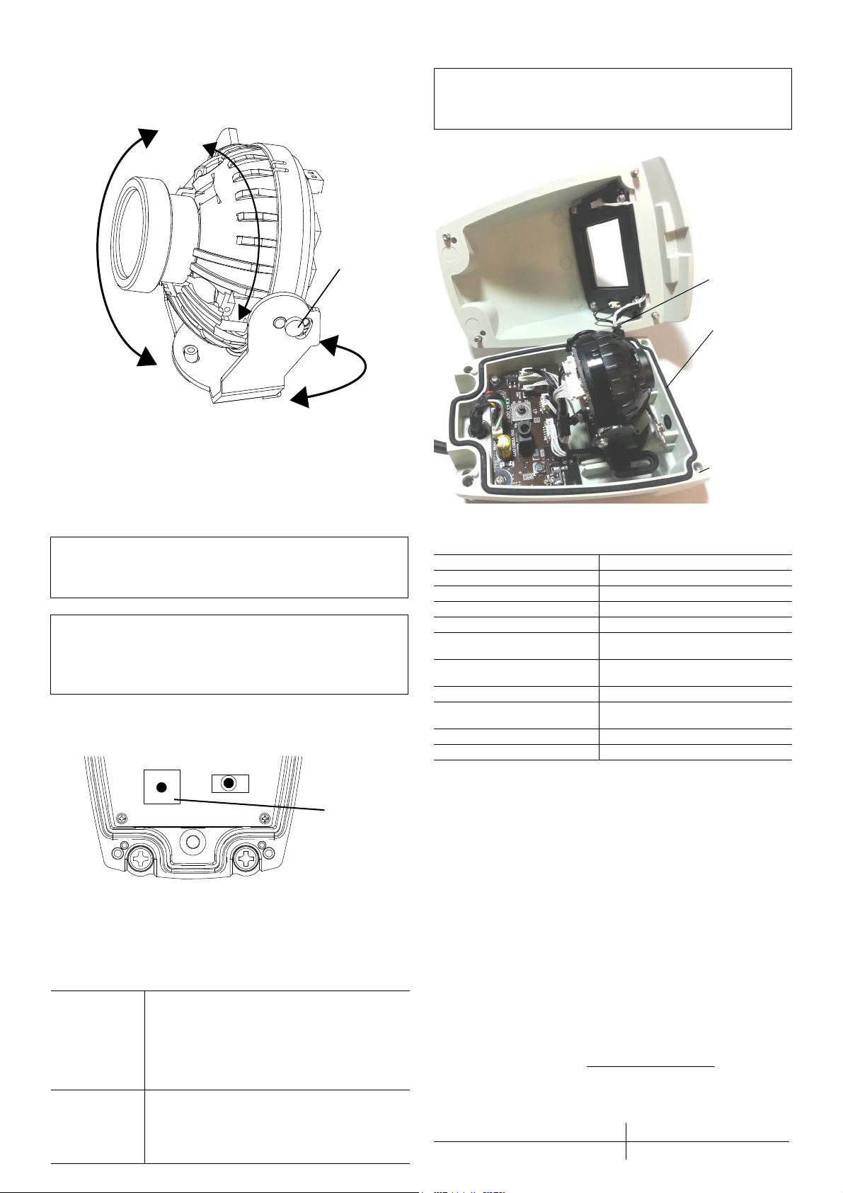
8. Replace Camera Housing
1. Close the housing back over onto the base.
2. Use the security key to tighten the four captive locking screws.
Specifications
Routine Maintenance
Most liquid cleaners or graffiti gel can be used to clean your camera enclosure. Do
not use abrasive cleaners that can scratch the window and reduce visibility of the
camera.
Replacing Damaged Camera
If the camera housing and window is damaged or scratched, order a replacement
camera from your camera distributor.
To remove and replace the housing, follow the steps in section 3 Open the
Camera and section 8 Replace Camera Housing.
Service
If your HD1W Wedge Camera is to be returned to Seon Design for service, please
call toll free 1-877-630-7366, or 604-941-0880, and provide the model and/or
serial number of your unit. Ask for a Return Authorization (RA) number. An RA
number allows the Service Technicians to better track your product when it comes
in for service. Please show the RA number on the outside of the package.
ANY PRODUCT SENT TO SEON DESIGN WITHOUT AN RA
NUMBER MAY BE REFUSED.
Warranty
For full warranty information, go to www.seon.com/warranty.html.
Information in this guide is subject to change without notice.
Customer Service Contact Information
INSTALL TIP: Do not adjust any other screws
The HD1W camera has been factory adjusted for lens position. Sliding
back the gimbal may result in the camera seeing parts of the housing.
INSTALL TIP:
Check video output from DVR after
camera housing is replaced
Ensure the desired field of view is achieved, and adjust if camera
housing obstructs the view.
BLC
(Back Light
Compensation)
WDR
(Wide Dynamic
Range)
• OFF: (default) shutter speed is based on the
light level of the entire image.
• BLC: helps improve image quality when back
lighting is strong.
• WDR: helps reduce glare for scenes with
simultaneous wide variance in lighting.
External LED • OFF: IR is disabled. Use in product
configurations where IR is not required.
• AUTO: (default) IR LEDs illuminate
automatically upon HD1W sensing a low light
condition.
Rotate
Figure 4
Tilt
Tilt
adjustment
screws
(2nd not
shown)
Pan
Figure 5
Menu button
UP
2ND VIDEO OUT
DOWN
CAUTION: Do not pinch safety wire
Ensure closing the cover does not pinch the wire connecting the cover
to the base. This can allow moisture to enter and damage the unit.
Power Consumption
5 W max. @ 12 VDC
Operating Voltage Range
9 to 14 VDC (powered by DVR)
Operating Temperature Range
-40 to 122°F (-40 to 50°C)
Horizontal resolution
720p
Infrared LED Lamps
4 high efficiency LEDs
Minimum Illumination
0.7 lux at F2.0
0 lux (IR on)
Enclosure Size, LxWxH
5.16" (131 mm) x 3.45" (88 mm) x 3"
(77 mm)
Enclosure Material
Solid aluminum alloy, powder coated
Window
Impact-resistant polycarbonate,
scratch-resistant, UV protected
Connector Cable Length
9.5" (24.1 cm)
Weight
1.22 lbs (554 g)
Toll free telephone 1-877-630-7366 Local telephone 604-941-0880
Email: [email protected]m Web: www.seon.com
Figure 6
LED and Ground
connection wires
Camera sealing
gasket
Base
(Do not apply
sealant around
base)