TS7000 MATERIAL HANDLER OPERATORS MANUAL - VERSION I Page 10
SAFE-AID TS7000 SYSTEM ERROR TABLE – TABLE #1
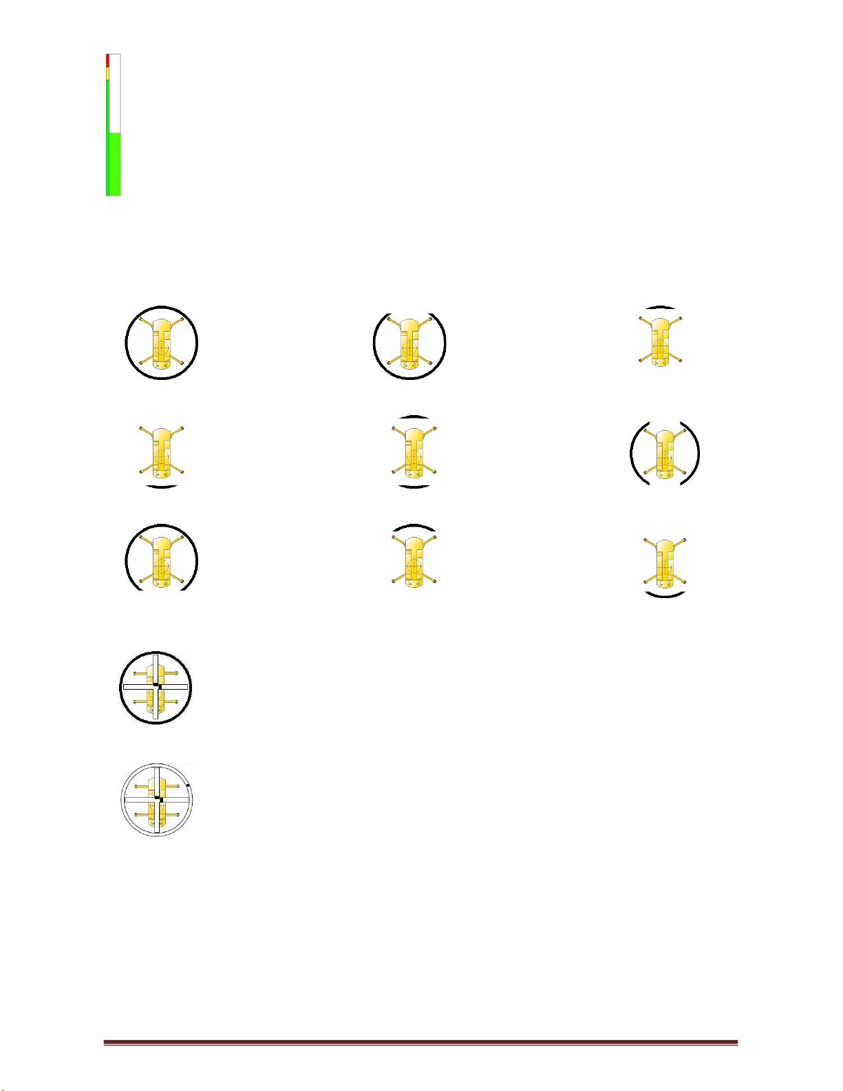
CODE SCREEN DISPLAY INDICATION OPERATOR SOLUTION
E001 Slew Error Boom is not over an area covered by the current
Slew the boom into a safe working area.
E004 90% Overload The lifted load is greater than or equal to 90% of the
rated capacity
Move load into safe working position -
winch down, boom up or retract boom.
E005 Overload The lifted load is greater than or equal to 100% of the
rated capacity
Move load into safe working position -
winch down, boom up or retract boom.
E008 Low Angle The angle of the boom is below the crane manufacturer's
minimum specification. Raise boom.
E027 Main A400 No Coms No communication between main angle board and
motherboard/display. Call installer or service technician.
E028 Aux A400 No Coms No communication between auxiliary angle board and
motherboard/display. Call installer or service technician.
E029 M400 No Coms
No communication between mother board and display.
Call installer or service technician.
E033 R400 No Coms No communication between relay board and
motherboard/display. Call installer or service technician.
E034 No Load Chart Data You are working out of the manufactures specified
working range – incorrect working radius
Lower Boom to within the manufacturers
specified working range.
E035 No Moment Value Pressure Error No empty and loaded moment data at
specific length and angle.
E036 Tilt Error X Axis Crane has tilted over maximum allowed tilt on the X axis
(Left & right of carrier) Level crane to within specified tilt range.
E037 Tilt Error Y Axis Crane has tilted over maximum allowed tilt on the Y axis
(Front & rear of carrier) Level crane to within specified tilt range.
E040 A400 Tilt No Coms No communication between A400 Tilt board and
motherboard/display. Call installer or service technician.
E045 Main Dump Short Circuit Short circuit on the Main Dump Output. Call installer or service technician.