Safegate Group Airfield Lighting 8-135 Series User manual

Airfield Lighting
Manual
Base 8”-135 mm
Base 12”-150 mm
Ground Fixing of 8” Inset Light Fittings
(8” Base)
Ground Fixing of 12” Inset Light
Fittings (12” Base)

Note: This page is blank for convenient double-sided printing.

Airfield Lighting Safegate Group
Manual Date: March 2016
Ref: Base 8"/135mm, Base 12"/150mm Version: 2.0
Page 1 of 26
MANUAL
BASE 8”-135 MM
BASE 12”-150 MM
CONTENTS
Section Description Page No.
1. INTRODUCTION ...........................................................................................................3
1.1 SAFETY INSTRUCTIONS................................................................................3
1.2 DELIVERY OF UNITS ......................................................................................3
1.3 OVERVIEW OF UNIT TYPES ..........................................................................3
1.4 BASE OPTIONS ...............................................................................................4
2. INSTALLATION.............................................................................................................9
2.1 CABLING OPTIONS.........................................................................................9
2.2 CIVIL WORKS.................................................................................................10
2.2.1 Conduct ....................................................................................................10
2.2.2 Coring........................................................................................................10
2.2.3 Final Preparation......................................................................................11
2.3 ELECTRICAL CONNECTIONS ......................................................................12
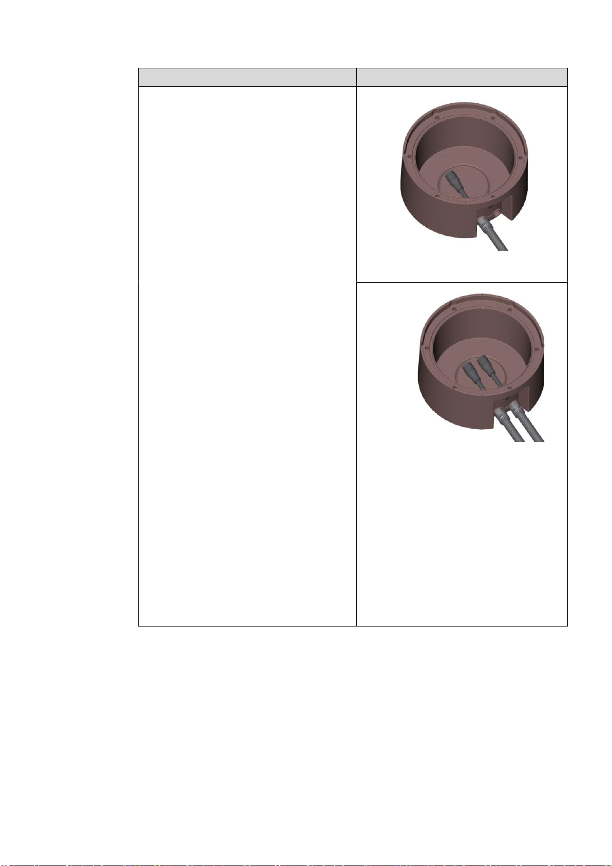
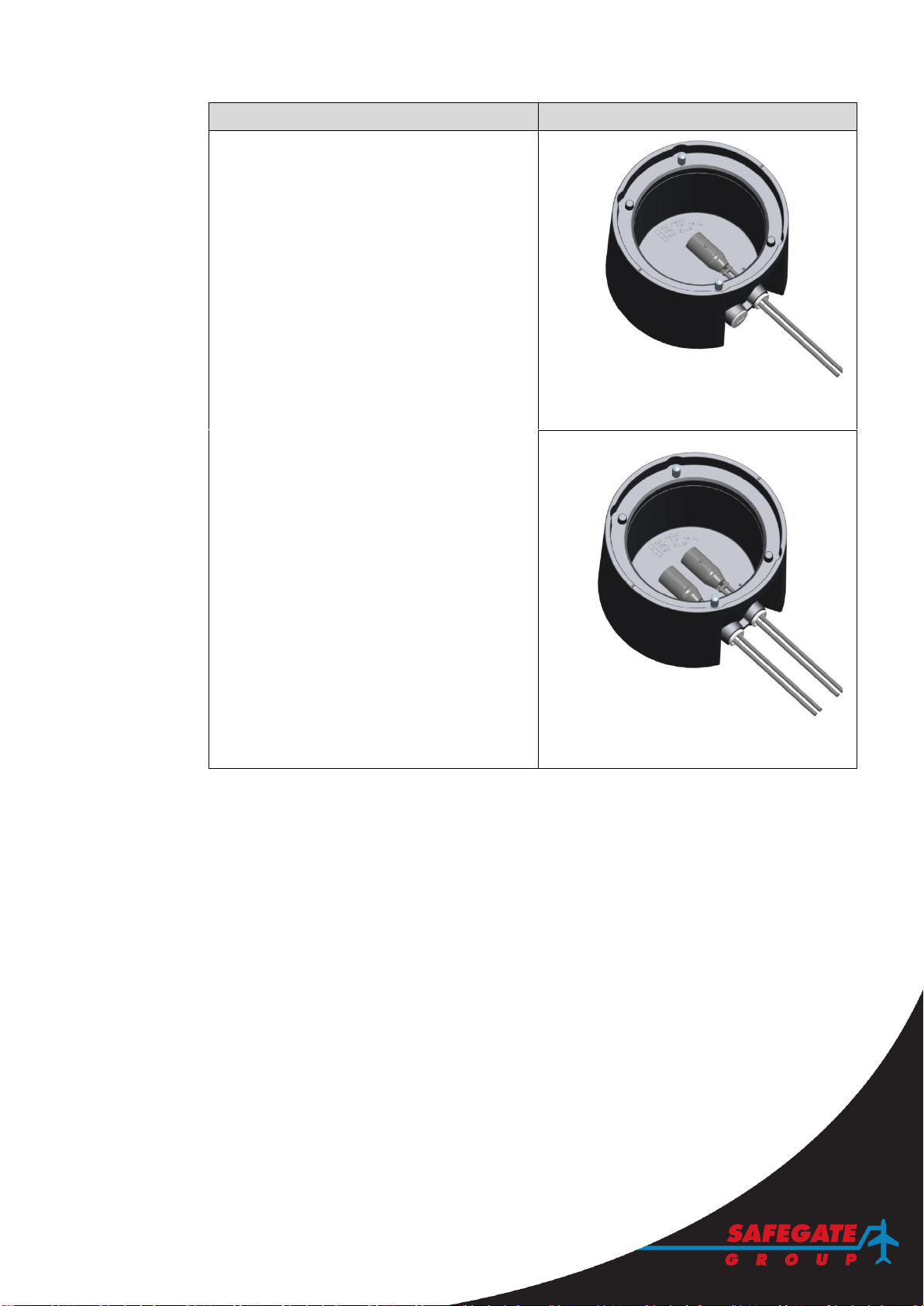
2.3.1 Electrical Connections in Base with Bottom Access...........................12
2.3.2 Electrical Connections in Base with Side Access................................13
2.4 INSTALLING THE BASE................................................................................15
2.4.1 Positioning and Alignment of a Base ....................................................15
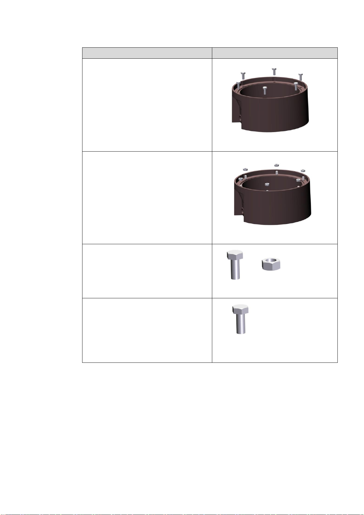
2.4.2 Fixation of a Base....................................................................................21
2.5 INSTALLING A FITTING.................................................................................22
3. MAINTENANCE ..........................................................................................................23
4. SUPPORT....................................................................................................................24
4.1 SAFEGATE GROUP WEBSITE .....................................................................24
4.2 RE-CYCLING..................................................................................................25
4.2.1 Local Authority Re-cycling .....................................................................25
4.2.2 Safegate Group Re-cycling.....................................................................25
4.3 SPARE PARTS & ACCESORIES...................................................................25

Airfield Lighting Safegate Group
Manual Date: March 2016
Ref: Base 8"/135mm, Base 12"/150mm Version: 2.0
Page 2 of 26
Documentation
This document includes Airfield Lighting information with focus on safety, installation
and maintenance procedures.
Note: It is very important to read and perceive this document before any work is
started.
Original documentation is created in English and in the case of contradictory
information between English and translated version English version is valid.
Images and texts used in this documentation are reference examples only and may
not exactly depict a customer product.
Safegate continuously develop products and documentation. New versions for
documents are released at undefined intervals without particularly informing customer.
If it seems that something is missing or unclearly presented check for latest version of
document.
For more information, see www.safegate.com.
Copyright
© Copyright 2012 by Safegate Group. All rights reserved. This item and the
information contained herein are the property of Safegate Group. No part of this
document may be reproduced, transmitted, transcribed, stored in a retrieval system,
or translated into any language or computer language in any form or by any means
otherwise, without the expressed written permission of Safegate Group,
Djurhagegatan 19, SE-213 76 Malmö, Sweden.
History
Version Date Description
1.0 February 2014 First release
2.0 February 2015 Second release
Note: This page is to be updated with every authorized change to the document.

Airfield Lighting Safegate Group
Manual Date: March 2016
Ref: Base 8"/135mm, Base 12"/150mm Version: 2.0
Page 3 of 26
1. INTRODUCTION
Airfield inset light bases are receptacles for inset lights for site requirements at
airports. The bases are 8” and 12” in size and are compatible with Safegate Group
(Idman, Safegate and Thorn) inset lights. It may be possible to use with other
manufacturers light units; however compatibility must be checked separately.
1.1 SAFETY INSTRUCTIONS
WARNING! PRIOR TO THE COMMENCEMENT OF WORK ALL ELECTRICAL
SERVICES MUST BE ISOLATED FROM THE SUPPLY AND CONNECTED TO
EARTH. FULL DETAILS OF THE WORK INVOLVED MUST BE GIVEN TO THE
AUTHORISED PERSON RESPONSIBLE FOR THE ELECTRICAL ENGINEERING
SERVICES AT THE AIRPORT WITH REGARD TO THE DURATION OF THE WORK
AND SO ON. IT IS RECOMMENDED THAT PRIOR TO STARTING ANY CUTTING
WORK, THE NATURE AND LOCATION OF SERVICES SUCH AS CABLE DUCTS
AND THE LIKE SHOULD BE IDENTIFIED. ANY INSTALLATION OR MAINTENANCE
WORK SHOULD ONLY BE CARRIED OUT BY TRAINED AND EXPERIENCED
PERSONNEL. ALSO, WHEN WORKING ON CIRCUITS USING AIRFIELD SMART
POWER SYSTEM (ASP) THE SCM MUST BE TUNED OFF.
1.2 DELIVERY OF UNITS
To meet every customers individual requirements Base 8”/12” are delivered without
basic accessories such as: cable glands, cables, wiring protection tubes earth fixing
screws and nuts. Basic accessories and electrical connection kits for Base 8”/12”
must be ordered separately.
1.3 OVERVIEW OF UNIT TYPES
The different types of shallow bases supplied allow direct mounting of 8” and 12” inset
light fittings. Options available for bases do not affect what type of light unit that can
be used. The difference is the type of cabling system and the light fitting fixing system
to be utilized (Metric/UNC, Bolts/Nuts).

Airfield Lighting Safegate Group
Manual Date: March 2016
Ref: Base 8"/135mm, Base 12"/150mm Version: 2.0
Page 4 of 26
1.4 BASE OPTIONS
This section describes the options available for bases. It is possible for options to be
combined. For more information, contact Safegate.
Base
X - XXX
X
X
X
Components
M
= Metric threads (M10)
U
= UNC threads (UNC 3/8”)
T
= Insert thread version
S
= Stud bolt version (available only with
metric threads)
0
= Bottom-hole version, no cable side
entries.
2
= 2 open cable entries on side, no bottom
hole.
(Applicable for accessory kit 3)
3
= 2 open cable entries on side, no bottom
hole. (Applicable for accessory kit 1 and
2)
8” - 135
8” base, 135 mm total depth.
12” -150
12” base, 150 mm total depth.
* For more information about base accessories see Airfield Lighting Product
Description for Base 8”-135mm and Base 12”-150mm.

Airfield Lighting Safegate Group
Manual Date: March 2016
Ref: Base 8"/135mm, Base 12"/150mm Version: 2.0
Page 5 of 26
Base options
Image examples
Base 8”-135-0-X-X
Base 12”-150-0-X-X
The option includes:
0–Ø100 mm (8” bases), Ø130 mm (12”
bases) bottom entry for cables. This option is
for cabling in the field with buried conducts.
FIGURE –BOTTOM ENTRY FOR 8” BASE
FIGURE –BOTTOM ENTRY FOR 12” BASE

Airfield Lighting Safegate Group
Manual Date: March 2016
Ref: Base 8"/135mm, Base 12"/150mm Version: 2.0
Page 6 of 26
Base options
Image examples
Base 8”-135-2-X-X
Base 12”-150-2-X-X
The option includes:
2- two side entries for cables for cabling in
the field with saw cuts/grooves and two
secondary cables (Ø 10-14 mm).
One cable
1 x Cable connector kit, cable and connector
1 x Obstruction packer
Two Cables
2 x Cable connector kit, cables and
connectors
FIGURE –2 SIDE ENTRY FOR 12” BASE
–ONE CABLE
FIGURE –2 SIDE ENTRIES FOR 12” BASE
–TWO CABLES

Airfield Lighting Safegate Group
Manual Date: March 2016
Ref: Base 8"/135mm, Base 12"/150mm Version: 2.0
Page 7 of 26
Base options
Image examples
Base 8”-135-3-X-X
Base 12”-150-3-X-X
The option includes:
3–two side entries for cables (without plastic
tube) for cabling in the field with saw
cuts/grooves and one or two secondary
cables.
One cable
1 x Cable gland system
1 x Obstruction packer
Two Cables
2 x Cable gland systems
FIGURE –2 SIDE ENTRIES FOR 8” BASE
–ONE CABLE
FIGURE –2 SIDE ENTRIES FOR 8” BASE
–TWO CABLES

Airfield Lighting Safegate Group
Manual Date: March 2016
Ref: Base 8"/135mm, Base 12"/150mm Version: 2.0
Page 8 of 26
Base option
Image examples
Base 8”-135-X-T-X
Base 12”-150-X-T-X
The option includes:
T–replaceable, locking type stainless steel
thread elements.
Used when the light fittings are fixed with
bolts.
FIGURE –BOLTS
Base 8”-135-X-S-X
Base 12”-150-X-S-X
The option includes:
S–replaceable stainless steel stud bolts.
Used when the light fittings are fixed with
nuts.
Note: This option is only available with metric
threads.
FIGURE –NUTS
Base 8”-135-X-X-M
Base 12”-150-X-X-M
The option includes:
M–for light unit fixing with metric threads.
FIGURE –METRIC
Base 8”-135-X-X-U
Base 12”-150-X-X-U
The option includes:
U- for light unit fixing with UNC threads.
Note: This option is only available with
locking type stainless steel thread elements.
FIGURE –UNC
M10
UNC 3/8”

Airfield Lighting Safegate Group
Manual Date: March 2016
Ref: Base 8"/135mm, Base 12"/150mm Version: 2.0
Page 9 of 26
2. INSTALLATION
This section includes basic step-by-step instructions generally applicable for all
installation practices. However the installation steps may differ depending on site
requirements. Before you start, make sure you have read and understand § 1.1 Safety
Instructions.
An inset light fitting base uniquely defines position, orientation and level for the light
unit positioned in it. These criteria are defined during the base installation process and
are almost impossible to change afterwards. For this reason it is highly important that
base installation is carried out accordingly.
2.1 CABLING OPTIONS
Cabling option
Image examples
For installation using saw cuts made in the
layout to lead secondary cables, use a
shallow base with side entry/entries.
Note: Image example shows assembly of
12” base and fitting but is valid for
installation of 8” base and fittings as well.
FIGURE –SAW CUTS/SIDE ENTRY
For installation using buried conducts in the
layout to lead the secondary cables, use a
shallow base with bottom entry.
Note: Image example shows assembly of
12” base and fitting but is valid for
installation of 8” base and fittings as well.
FIGURE –BURIED CONDUCTS/BOTTOM ENTRY
For correct light location, orientation and so on it is recommended to read and comply
with the following:
ICAO: Annex 14 Volume I, which refers to lighting system installation in general.
All drawings and design plans, for the particular project, to guarantee correct
location and orientation for each light unit.
The following tools and accessories are required for installation and removal of the
unit:
Standard tools and accessories:
Standard surveying equipment.
Coring and cutting equipment with diamond blades (such as for pavement
surfaces).
Alignment device for the base.
Tools for electrical connection (depending on the cabling system, for example
cutting/striping pliers, crimping tool, hot air gun and the like).
22/24 mm fork wrench for cable gland.

Airfield Lighting Safegate Group
Manual Date: March 2016
Ref: Base 8"/135mm, Base 12"/150mm Version: 2.0
Page 10 of 26
8 mm socket wrench for a ground screw.
Two component fixing compound.
Cable groove sealer (saw cut/grooves cabling system only).
Note: The installation method used defines the tools and accessories required.
The installation steps refer to:
1. Civil works
2. Electrical connections
3. Installing the base
4. Installing the fitting
2.2 CIVIL WORKS
All necessary markings such as base positions, cable grooves and so on must be
accurately defined by a surveying team before any civil works start.
2.2.1 Conduct
Cable conducts methods for bases can be divided to two groups: buried cables and
saw cuts/grooves. The cable conduct system that is used influences the base
installation process and the order in which different steps can/must be carried out.
For a buried cable system, the supply cable for the fitting runs through a duct set in
the sub-base of the pavement, from the transformer pit to the underside of the base.
Bases with a bottom hole are to be used with this cable system.
For saw cuts/grooves cable system, the supply cable for the fitting runs through saw
cuts made in a pavement. The saw cut size must be in relation to the number and the
diameter of cables to be placed in it. It is recommended to bury cables to a depth of at
least 30 mm. Bases with side access are to be used with this cable system.
2.2.2 Coring
Cut a hole for a base:
Hole dimensions for Base 8”: Ø245 mm, depth 145 mm.
Hole dimensions for Base 12”: Ø345 mm, depth 160 mm.
After cutting, break out and remove the hole-centres for the base and for the bottom to
access cables, if required.
When installing a base with bottom access, cut a central hole into the sub-base
(≤ Ø100 mm for Base 8”, ≤ Ø130 mm for Base 12”) to be able to reach the cable
duct.
When installing a base with side access, make saw cuts and chamfers in order to
access cable inlets.

Airfield Lighting Safegate Group
Manual Date: March 2016
Ref: Base 8"/135mm, Base 12"/150mm Version: 2.0
Page 11 of 26
Cable conduct chamfers
Image examples
When installing Base 8” / 12” for saw
cut/grooves cable system, cable cuts must
be chambered as shown in the figure.
It is recommended that longitudinal angles
of the grooves should not exceed 30
degrees.
It is also important that minimum bending
radius for the cable type to be used is not
exceeded in any part of the groove.
For more information, see the cable
manufacturer’s technical data for minimum
radius.
FIGURE –CABLE CONDUCT
2.2.3 Final Preparation
After breaking out the saw cuts and the hole for the base, carefully clean and remove
all gravel, sand or waste material from the groove. Degrease and dry all surfaces of
the base that will be in contact with the resin. During the installation process, it is
recommended to protect the light fitting contact and gasket surfaces with masking
tape.
Make sure the resin to be used meets the manufacturer recommendations for:
Expiry date
Freedom from moisture, reduction of the risk for chemical reaction
Storage conditions
Working conditions
If the resin is acceptable for use, carefully read the manufacturer instructions for
mixing it, pouring it and so on. When determining the amount of resin to mix, consider
the working time of resin, the number of bases to be glued with the mixture and so on.
Note: Do not use resin that has passed the expiration date.
145 (Base 8”)
(Base 12”)

Airfield Lighting Safegate Group
Manual Date: March 2016
Ref: Base 8"/135mm, Base 12"/150mm Version: 2.0
Page 12 of 26
2.3 ELECTRICAL CONNECTIONS
Electrical connections to the base can be made in many different ways. Bases are
usually equipped with FAA Secondary Receptacles with different configurations such
as plugs connected to cable/wires or short cables with wire-to-wire. Electrical
connectors are not included in the base delivery and customers must order materials
based on the system to be used.
In many cases, cable/wires may be unprotected through the area where the base
fixing resin is spread. In such cases, cable/wires must be installed and the system
functionality tested before installing the base.
2.3.1 Electrical Connections in Base with Bottom Access
Electrical connections in a base with
bottom access
Image examples
(a) Feed the cable(s) into the base.
(b) Complete all electrical connections and
wire/connector screenings.
(c) Attach the ground wire (A) to its
connection point inside the base using
the screw supplied. For systems where
ground connection is used, the ground
cable needs to be equipped with a
suitable cable terminal.
Note: If the marked connection point
cannot be used, the screw can be
attached to any other place
inside/outside the base.
(d) Allow approximately 35 cm secondary
cable inside a 12” base respectively 25
cm inside an 8” base.
(e) Seal the bottom hole.
Note: It may not be possible to seal
before the alignment jig is set.
FIGURE –ELECTRICAL CONNECTION IN A BASE
WITH BOTTOM ACCESS

Airfield Lighting Safegate Group
Manual Date: March 2016
Ref: Base 8"/135mm, Base 12"/150mm Version: 2.0
Page 13 of 26
2.3.2 Electrical Connections in Base with Side Access
Note: If a base with side access is to be installed, it is possible to complete the
electrical connections after the base installation. It should thou be noticed that this is
not the general rule for this type of base installation or different installation processes.
Electrical connections in Base 12” and
Base 8”-135-2-X-X (with side access, full
threaded holes)
Image examples
(a) Install the cable gland on the inside of
the base and the plastic tube on the
outside. Loose the outer part of the
cable gland to allow the cable to pass
(B).
(b) Pull the cable through the protection
tube and the cable gland (C).
(c) Complete all electrical connections and
wire/connector screenings.
(d) Attach the ground wire (A) to its
connection point inside the base using
the screw supplied. For systems where
ground connection is used, the ground
cable needs to be equipped with a
suitable cable terminal.
Note: If the marked connection point
cannot be used, the screw can be
attached to any other place
inside/outside the base.
(e) Allow approximately 35 cm secondary
cable inside a 12” base respectively 25
cm inside a 8” base.
(f) Tighten the cable gland (B) with 24 mm
fork wrench.
FIGURE –ELECTRICAL CONNECTION IN A BASE
WITH SIDE ACCESS

Airfield Lighting Safegate Group
Manual Date: March 2016
Ref: Base 8"/135mm, Base 12"/150mm Version: 2.0
Page 14 of 26
Electrical connections Base 12” and
Base 8”-135-3-X-X (with side access,
partially threaded holes)
Image examples
A Connector Kit, separately supplied, is
required to install a connector on a shallow
base. The kit includes:
An FAA Secondary Receptacle
+ Wires (A).
A Compression Packer with:
oone rubber gasket (B)
oone washer (C)
oone nut (D)
(a) Install the FAA Secondary Receptacle
+ Wires from the kit (A).
From the inside of the base, feed the
two wires through the threaded hole of
the base (E).
(b) From the outside of the base, feed the
two wires of the connector through the
rubber gasket (B) and place it inside the
threaded hole of the base.
Note: Allow approximately 35 cm
secondary cable inside a 12” base
respectively 25 cm inside a 8” base.
(c) From the outside of the base, feed the
two wires of the connector through the
washer (C) and place it inside the
threaded hole of the base. From the
outside of the base, feed the two wires
of the connector through the nut (D) on
and fasten it in the threaded hole of the
base.
(d) Fasten the nut in the threaded hole of
the base; there is no torque for cable
gland as it is fastened onto rubber.
Note: For bases with two connectors,
repeat these steps to install a second
connector.
Shallow bases with side access are
supplied with two threaded holes.
Shallow bases supplied with only one
connector require the second hole to be
plugged with an Obstruction Cap.
Note: An Obstruction Cap Kit is ordered
separately.
(e) Install an obstruction cap (F). From the
outside of the base, position the
obstruction cap in the threaded hole of
the base.
(f) Fasten the obstruction cap in the
threaded hole of the base.
Installation of ground screws in a
8” base
Image examples
Ⓔ
Ⓑ
Ⓒ
Ⓐ
Ⓕ
Ⓓ
Ⓓ
Ⓕ

Airfield Lighting Safegate Group
Manual Date: March 2016
Ref: Base 8"/135mm, Base 12"/150mm Version: 2.0
Page 15 of 26
When a base (and/or a light fixture) is to be
grounded to earth, the install of ground
screws (supplied separately) in the base is
needed:
(a) Install an internal ground screw (G).
From the inside of the base, fasten the
self-drilling and threading screw in the
specific countersink marked with ground
symbol.
(b) Install an external ground screw (G).
From the outside of the base, fasten the
self-drilling and threading screw in one
of the two possible specific countersinks
(see position in the figure to the right).
2.4 INSTALLING THE BASE
The following installation procedure provides step-by-step instructions for a single
base fixing. However, it is recommended to install several bases at the same time as
some steps (such as fixing compound spreading) are carried out more effectively on a
multi-base installation.
2.4.1 Positioning and Alignment of a Base
When installing bases, an alignment device is needed in order to position and fixate
the base in the ground. Depending on base model, size, function and installation
requirements different models of alignment devices are needed.
When installing bases on runways according to ICAO (Annex 14 Volume 1,
Aerodrome Design and Operations, 6th edition, July 2013, Appendix 2), an alignment
tool with horizontal adjustment is needed. If positioning jig for 8”-bases is used, note
that the applicable version is the one produced year 2014 or later. When installing
bases on taxiways, horizontal adjustment is not required.
For easier and more accurate base installation when using Positioning jig for 8”/12”-
bases, an optional tool called Sight Telescope can be used. Instructions for how to
use the Positioning jig and the Sight Telescope can be found later on in this chapter.
The matrix below describes the main functions of Safegate Groups four alignment
devices for bases.
Ⓖ

Airfield Lighting Safegate Group
Manual Date: March 2016
Ref: Base 8"/135mm, Base 12"/150mm Version: 2.0
Page 16 of 26
Positioning jig
for 8”-bases*
(Vertical and
horizontal-
adjustment)
Positioning jig
for 12”-bases
(Vertical and
horizontal-
adjustment)
IDM 6092
for 8”-bases
(Vertical-
adjustment)
IDM 4306
for 12”-bases
(Vertical-
adjustment)
ICAO Annex 14
Annex 14
Volume 1,
Aerodrome
Design and
Operations, 6th
edition, July
2013,
Appendix 2
(For installation
on Runway)
Yes
Yes
No
No
ICAO Annex 14
Volume 1,
Aerodrome
Design and
Operations, 6th
edition, July
2013,
Appendix 2
(For installation
on Taxiway)
Yes
Yes
Yes
Yes
FAA AC
150/5340-30G
Yes
Yes
Yes
Yes
Insert thread
base versions
Yes
Yes
Yes
Yes
Stud bolt base
versions
Yes
Yes
No
No
Note: Find out more about the devices and installation process in the next coming
pages.
* produced year 2014 or later

Airfield Lighting Safegate Group
Manual Date: March 2016
Ref: Base 8"/135mm, Base 12"/150mm Version: 2.0
Page 17 of 26
Set up alignment devices
IDM 6092 (8”) and IDM 4306 (12”)
Image examples
An alignment device is used for aligning
bases parallel to a centre line, toe-in bases
and also for curved section bases.
The device includes:
Fastening screws (A).
Screw holes for straight sections (B).
Screw holes for curved sections (C).
Angle scale (D).
Alignment grooves (E).
When a base parallel to a centre line or toe-in
base is to be installed, set fastening screws
for screw holes for a straight section.
When a curved section base is to be
installed, set fastening screws for the screw
holes for a curved section.
FIGURE –ALIGNMENT DEVICE (IDM 4306)
Set up for base installation parallel to
centre line and toe-in:
(a) Place the alignment device on the base.
(b) Tighten the fastening screws.
(c) Set the angle scale to the desired value
(0° for a parallel to centre line base) and
check both scales show the same value.
(d) Tighten fastening screws.
Note: For 12” base, side access can be
aimed to six different directions depending on
which index alignment tool is set.
FIGURE –PARALLEL CENTRE LINE
Set up for curved section base
installation:
(a) Place the alignment device on the base.
(b) Tighten the fastening screws.
Note: For 12” base, side access can be
aimed to six different directions depending on
which index alignment tool is set.
For a curved section base, align by aiming
the alignment tool towards the curve centre.
FIGURE –CURVED SECTION

Airfield Lighting Safegate Group
Manual Date: March 2016
Ref: Base 8"/135mm, Base 12"/150mm Version: 2.0
Page 18 of 26
Position and align the base
Image Examples
(a) Make sure that the hole is clean and
completely dry.
(b) Make sure that the outer surfaces of
the base are clean and dry.
(c) Place the base in the installation hole
(with the alignment device).
(d) Centre the base in the middle of the
installation hole and align it using the
alignment grooves. For centre line
alignment, use for example the pre-set
aiming target or use the runway/taxiway
edge as a reference. For a curved
section, use the pre-set centre point
marker.
(e) Check that the alignment device is set
to the correct angle, the base is in the
middle of the installation hole and
alignment is correct.
(f) For a bottom-hole base, make sure that
the bottom hole is correctly sealed.
FIGURE –POSITION & ALIGN
Set up alignment devices Positioning jig
for 8”/12” bases and Sight Telescope
(optional)
Image examples
(a) Degrease and dry the base, if required.
Note: This is not required if the base is
new from the box.
(b) Place a specific positioning tool (8" or
12") on the base.
(c) Fasten the fixing knobs (nuts).
(d) Carefully place the base inside the bore
hole.
This manual suits for next models
1
Table of contents
Other Safegate Group Lighting Equipment manuals