Safety Vision SV-LCD56 User manual

SV-LCD56/64/68 Quick Installation Guide May 2007
Copyright © 2007 Safety Vision, LLC
All rights reserved.
Safety Vision and the Safety Vision logo are trademarks of Safety Vision, LLC
Notice to Users: This document is confidential and contains proprietary information belonging to Safety Vision, LLC This document and the
information contained herein cannot be distributed, communicated, reproduced, altered, or disseminated by any means, in whole or in part,
without the express written consent of Safety Vision, LLC Possession of this document constitutes the user’s acceptance of these nondisclosure
covenants. The information in this document is believed to be accurate in all respects. However, Safety Vision cannot assume responsibility for
any consequences resulting from the use thereof. The information contained herein is subject to change without notice. Revisions or new
editions to this publication may be issued to incorporate such changes.
Safety Vision ▪6100 West Sam Houston Parkway North ▪Houston, Texas 77041 ▪USA
SV-LCD56_64_68 QIG Ver.1.1 1
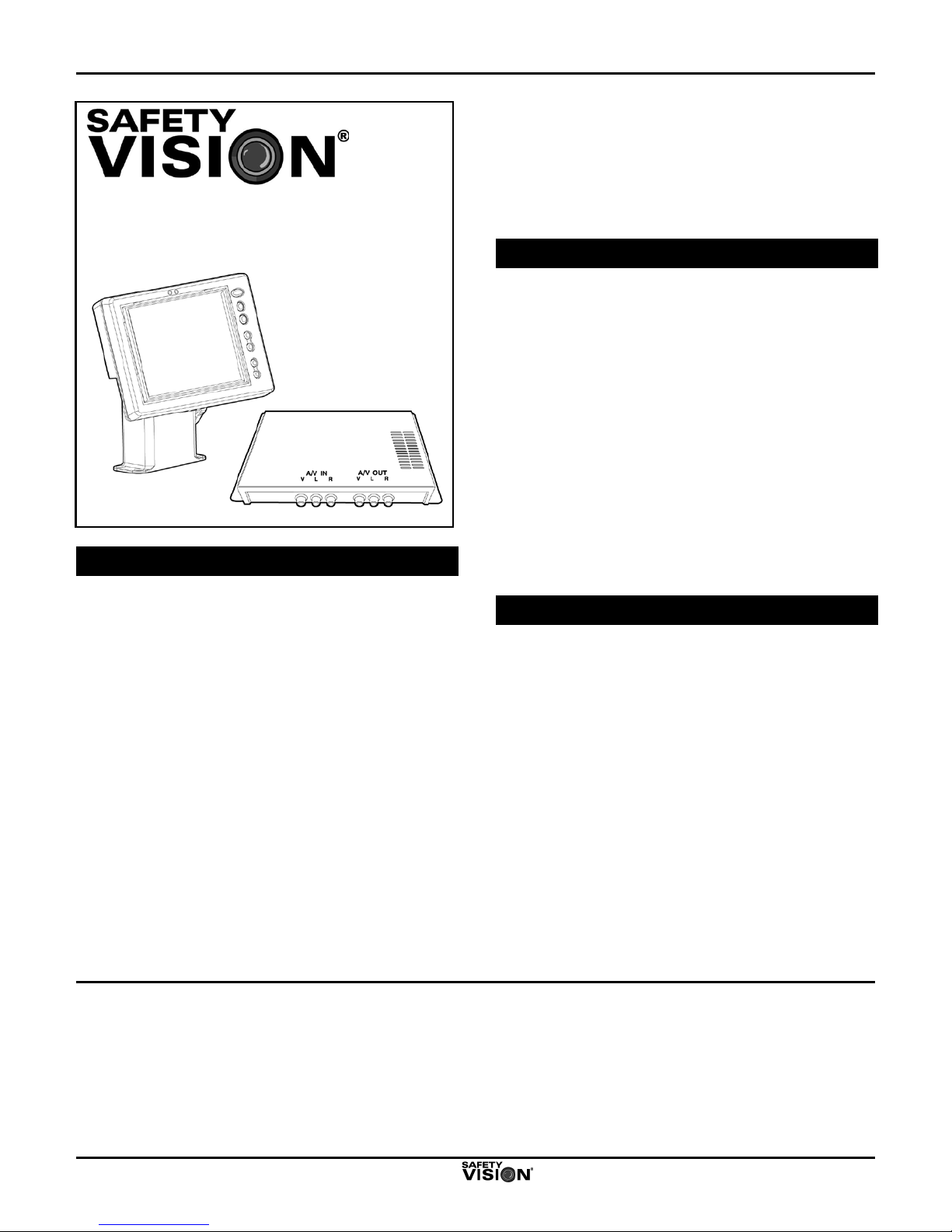
Safety Vision SV-LCD56/64/68
Color TFT LCD Rear Vision System
Quick Installation Guide
Overview
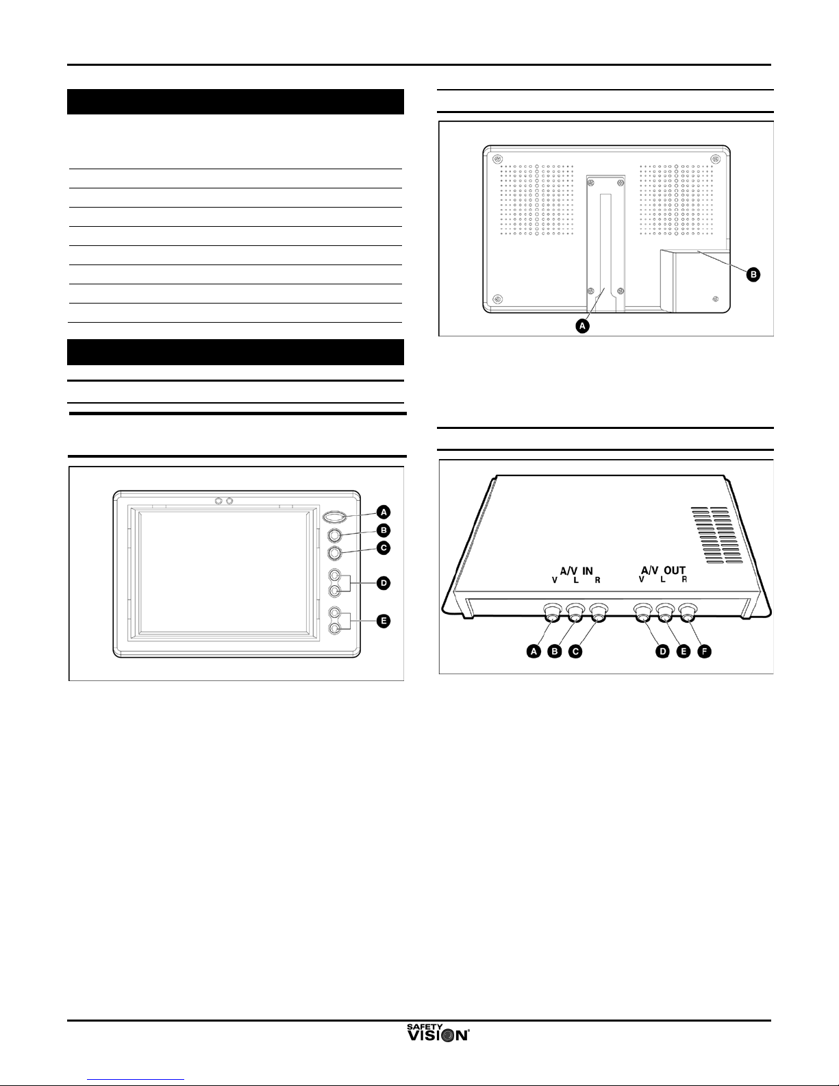
The Safety Vision SV-LCD56, SV-LCD64, and SV-
LCD68 TFT LCD Rear Vision Camera Systems turn
on automatically when the vehicle transmission is in
reverse gear. The systems accept input from up to
three cameras (supplied separately), and when
connected cameras have integrated microphones, the
systems allow the driver to both see and hear activity
behind the vehicle. Components of the SV-
LCD56/64/68 system are shipped separately and
include:
One of the following Safety Vision TFT LCD
monitors:
5.6-inch monitor (with the SV-LCD56 TFT LCD
Rear Vision Camera System)
6.4-inch monitor (with the SV-LCD64 TFT LCD
Rear Vision Camera System)
6.8-inch monitor (with the SV-LCD68 TFT LCD
Rear Vision Camera System)
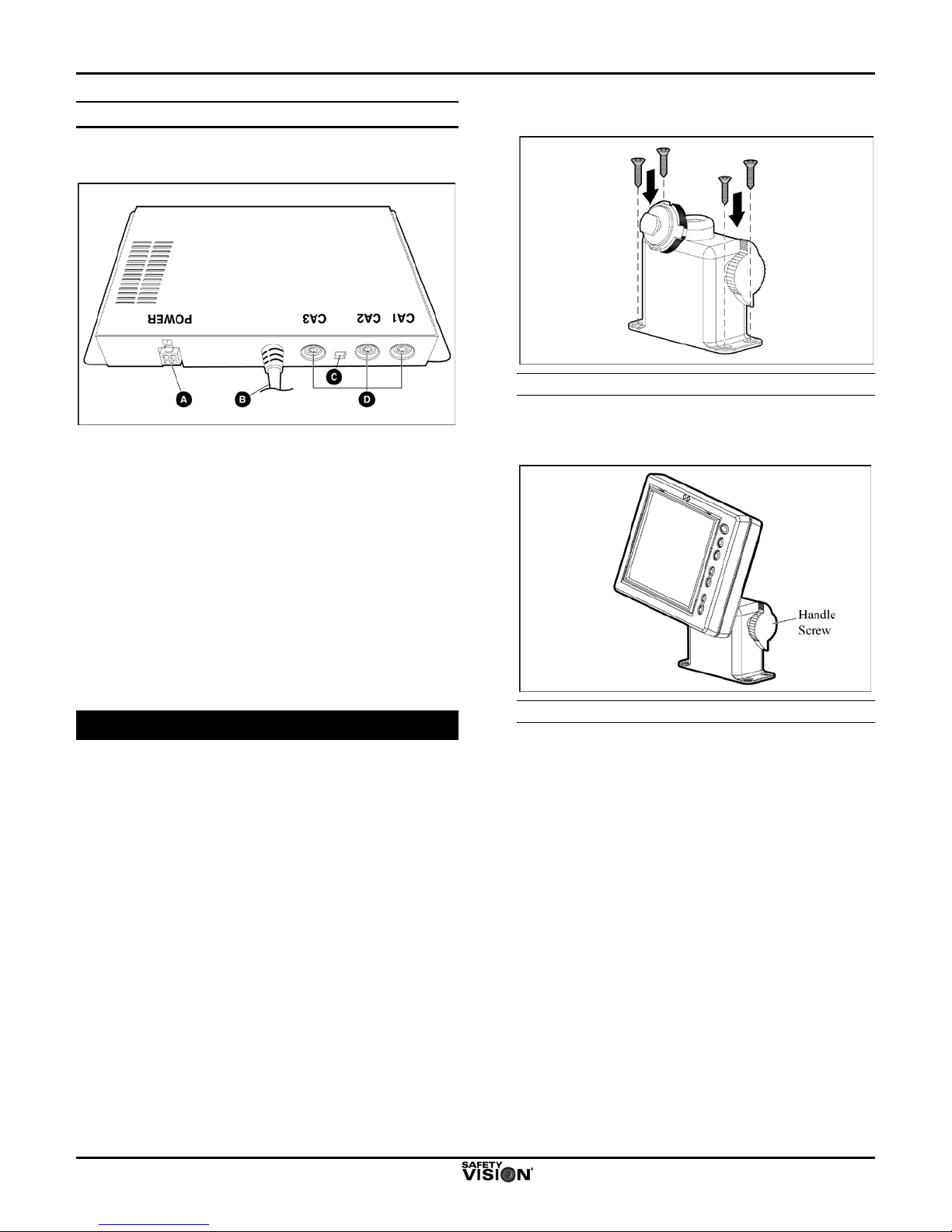
Safety Vision SV-LCDCB-PKKIT Control Box,
which provides DC power to the monitor and
cameras and features:
4 audio/video inputs, including 3 4-pin Mini DIN
and 1 RCA-type
1 RCA-type audio/video output
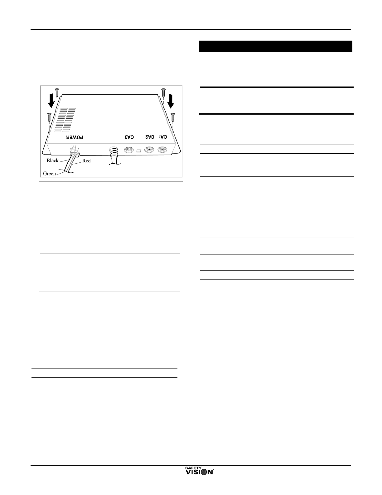
Important Safety Precautions
Install and operate the SV-LCD56/64/68system with
the following safety precautions in mind:
The ground (black) wire of the control box power
cable must be connected directly to the vehicle
chassis.
Use only the correct voltage (10 to 32 VDC).
The system is not waterproof. Do not expose the
monitor or control box to water or other liquids.
To avoid the risk of electric shock, do not
disassemble the system components, and keep
cables away from sharp objects.
This system is designed to assist the vehicle driver
with rear vision only. Do not attempt to view the
monitor while driving forward. Do not attempt to
operate the control box while driving.
Installation Considerations
Read this guide before installing or operating this
product.
The monitor and control box must be installed in
locations that are:
Waterproof
Not extremely hot or humid
Ventilated adequately
Capable of supporting a weight of 2.2 pounds (1.0
kg)
Select inconspicuous cable routes that do not interfere
with normal driver or passenger mobility.

SV-LCD56/64/68 Quick Installation Guide May 2007
SV-LCD56_64_68 QIG Ver.1.1 2
Supplied Hardware
The following hardware is supplied for installation with
each SV-LCD56/64/68system:
Hardware Item
Quantity
Monitor
1
Monitor Cable
1
Monitor Bracket
1
Monitor Screw Kit
1
SV-LCDCB-PKKIT Control Box
1
Control Box Power Cord
1
Control Box Screw Kit
1
Component Descriptions
Monitor Front Panel
NOTE:
The 5.6-inch monitor is shown in the following
illustrations.
A
POWER LED—This LED indicates that the
monitor has power. (The monitor is powered on
automatically whenever the vehicle ignition is
on.)
B
CA SEL BUTTON—When more than one
camera is connected to the system, this button
switches input between cameras. On-screen
identification of the active camera is displayed.
C
MENU BUTTON—This button initiates display of
the main menu.
D
VOL CONTROL BUTTONS—These buttons
increase and decrease the volume of the
integrated speaker. The on-screen display
indicates volume level.
E
CH BUTTONS—These buttons move the cursor
within the menu.
Monitor Rear Panel
A
BRACKET SLOT—This slot accepts the adjustable
mounting bracket.
B
INPUT—accepts the male 16-pin GPIB connector of
the supplied monitor cable. It receives power and
camera images from the control box.
Control Box Front Panel
A
VIDEO INPUT—accepts the RCA-type connector of
an optional input device such as a DVD player,
VCR, or additional camera (not used in typical
installations)
B
AUDIO INPUT (LEFT)—accepts the RCA-type
connector of an optional input device such as a
DVD player or VCR (not used in typical
installations)
C
AUDIO INPUT (RIGHT)—accepts the RCA-type
connector of an optional input device such as a
DVD player or VCR (not used in typical
installations)
D
VIDEO OUTPUT—sends video out through the
RCA-type video connector (not used in typical
installations)
E
AUDIO OUTPUT (LEFT)
—sends audio out through
the RCA-type left audio connector (not used in
typical installations)
F
AUDIO OUTPUT (RIGHT)—sends audio out
through the RCA-type right audio connector (not
used in typical installations)

SV-LCD56/64/68 Quick Installation Guide May 2007
SV-LCD56_64_68 QIG Ver.1.1 3
Control Box Rear Panel
Figure 7 shows the rear-panel components of the
control box. Component descriptions follow.
A
POWER—This receptacle accepts the 4-pin
Molex connector of the supplied power cable.
B
AUDIO/VIDEO OUTPUT
—This attached cable
connects the monitor
to the system, providing
power and audio/video signals to the monitor.
C
MIRROR/NORMAL SWITCHES—These
switches control the mirror/normal image setting
for cameras connected to CA2 and CA3.
D
CA1, CA2, and CA3—Each of these receptacles
accepts the connec
tor of a camera cable and
supplies power to the camera. By default, the
view from the camera connected to CA1 is
displayed when the vehicle transmission is in
reverse gear.
Typical Installation
Monitor
1. Select a level mounting location for the monitor,
which can be mounted overhead or elsewhere in
the vehicle cabin (including on the floor or
console).
2. Affix the monitor bracket to the mounting surface
with the supplied monitor screw kit.
Installing the Monitor Bracket
3. Position the monitor in the monitor mounting
bracket, adjust the angle as necessary, and tighten
the handle screw.
Installing the Monitor in the Bracket

SV-LCD56/64/68 Quick Installation Guide May 2007
SV-LCD56_64_68 QIG Ver.1.1 4
Control Box
1. Select a discreet location for the control box, such
as under the vehicle dashboard, and affix the
control box to the mounting surface with the
provided screws.
Installing the Control Box
2. Connect the unterminated wires of the control box
power cord as follows:
Wire Color
Vehicle Location
Red
Vehicle wire that has 12 VDC
when the vehicle ignition is on
Black
(Ground)
Vehicle chassis
Green
Vehicle wire that has 12 VDC
when the vehicle transmission
is in reverse gear (such as the
wire for the backup lights or
backup alarm)
Configuring the Camera(s)
Cameras are supplied separately. Up to 3 cameras
can be connected to the SV-LCD56/64/68system
Connect the cable of each installed camera to the SV-
LCDCB-PKKIT control box as follows:
Camera*
Control Box
Connector
Camera 1
CA1
Camera 2
CA2
Camera 3
CA3
*NOTE: Camera 1 is the main camera. By default, the
view from Camera 1 is displayed when the vehicle
transmission is in reverse gear. If additional cameras are
installed, a view from Camera 2 or Camera 3 can be
selected manually with the camera selector button on the
front panel of the monitor.
Initial Setup
To initiate display of the main menu, press the MENU
button on the front panel of the monitor. When you
have finished setting up a menu item, press the
MENU button again to save the changes.
NOTE:
After 5 seconds of inactivity, the menu is no longer
displayed, and the MENU button must be pressed
again to initiate display of the main menu again.
Use the monitor’s VOLUME AND CHANNEL buttons
to move the cursor and make menu selections. Menu
items can be changed as follows:
Menu Item*
Function
SCALE
Provides the distance between the
vehicle and other objects in the
camera’s view.
CA1
(MIRROR)
Controls the mirror/normal image
setting for Camera 1. (In Mirror
mode, the image is displayed in
reverse [as it would be displayed in a
rear-view mirror].)
AUTO TIME
Controls the scanning duration of
each camera connected to the rear
vision system
COLOR
Adjusts the color intensity level
BRIGHT
Adjusts the brightness intensity level
CONTRAST
Adjusts the contrast level between
dark and light images
TINT
Adjusts the color balance
*NOTE: Camera 1 is the main camera. By default, the
view from Camera 1 is displayed when the vehicle
transmission is in reverse gear. If additional cameras are
installed, a view from Camera 2 or Camera 3 can be
selected manually with the camera selector button on the
front panel of the monitor.

SV-LCD56/64/68 Quick Installation Guide May 2007
SV-LCD56_64_68 QIG Ver.1.1 5
Specifications
Monitor
Item
Specification
Power Input
12 VDC (from control box)
Power Consumption
Maximum 12 watts
Video System
NTSC
Sync System
Internal
LCD Panel Size 5.6-inch, 6.4-inch, or 6.8-inch
(diagonal)
Field of View
Top: 10°, Bottom: 30°
Left: 45°, Right: 45°
Screen Size
Width x Height 5.6-inch:
4.4 x 3.3 inch
(113 x 84.7 mm)
6.4-inch: 5.1 x 3.9 inch
(130 x 98 mm)
6.8-inch: 5.4 x 4.1 inch
(138 x 103 mm)
Resolution
Width x Height
960 x 234 pixels
Automatic Dimmer
Auto/Manual selectable
Color Configuration
RGB stripe
Automatic Brightness
Control
Light sensor, Day/Night switch
On-Screen Display
Controls Brightness, Contrast, Color,
Tint, CA1 Image Select
(Mirror/Normal), Auto Scan
Time, Scale On/Off
Power Connector
16-pin GPIB connector
Speaker Impedance
8 ohm, 0.5 watt maximum
Finish
Black PC/ABS
Operating Temperature
32°F to 122°F (0°C to 50°C)
Storage Temperature
-13°F to 176°F (-25°C to 80°C)
Ambient Condition
Indoor use only
Impact Rating
4G
Dimensions
(Width x Height x Depth)
5.6-inch:
6.8 x 4.5 x 1.1 inch
(173 x 114 x 28 mm)
6.4-inch: 7.7 x 5.5 x 1.1 inch
(196 x 140 x 28 mm)
6.8-inch: 7.7 x 5.5 x 1.1 inch
(196 x 140 x 28 mm)
Weight
5.6-inch:
0.8 pounds (0.36kg)
6.4-inch: 1.1 pounds (0.5 kg)
6.8-inch: 1.3 pounds (0.6 kg)
SV-LCDCB-PKKIT Control Box
Item
Specification
Power Input
10 ~ 32 VDC
Power Consumption
Maximum 18 watts
Video System
NTSC
Sync System
Internal
Video Input (4 Total)
4-pin Mini DIN (3)
RCA-type (1)
Audio Input (4 Total)
4-pin Mini DIN (3)
RCA-type (1)
Video Output
RCA-type (1)
Audio Output
RCA-type (2)
Housing
Steel
Operating Temperature
14°F to 122 °F (-10°C to 50°C)
Storage Temperature -13°F to 176 °F (-25°C to
80°C)
Ambient Condition
Indoor use only
Impact Rating
4G
Dimensions
Width x Height x Depth
6.5(W) x 4.6(H) x 7.4(D) inch
166(W) x 117(H) x 187(D) mm
Weight
2.2 pounds (1.0 kg)
Warranty Information
LIMITED 1-YEAR NEW PRODUCT WARRANTY
Safety Vision, LLC (“SV”) makes the following limited
warranty, which is effective at the time of the original end-
user purchase.
NOTE:
Optional warranty products are available for all SV
products and may be purchased at the time of the
original end-user purchase or any time during the
original Limited 1-Year New Product Warranty period.
SV warrants this product against defects in materials for a
period of 1 year after the date of purchase. During this
period, SV will repair or replace a defective product or part
without charge to the customer. The customer must send
the defective product or part to SV or an authorized SV
dealer. The customer must pay for all transportation and
insurance charges for sending the unit to be repaired. SV’s
total liability is limited to the original product cost.
Quick Installation Guide
The customer should thoroughly read this guide before
operating this product.
Customer’s Responsibility
The above warranty is subject to the following conditions:
Customer must notify SV within 10 days of discovering
the defective product or part and provide a description of
the defect and complete information about the manner of
its discovery.
All warranty servicing of this product must be performed
by SV or an authorized servicing agent.
Warranty extends only to defects in materials as limited
above. Warranty does not extend to any product or part
that has been lost or discarded by the customer; to
damage to products or parts caused by misuse,
accident, improper installation, improper maintenance, or
use in violation of instructions furnished with the product;
to units that have been altered or modified without
authorization of SV; to damage to products or parts
thereof that have had the serial number removed,
altered, defaced, or rendered illegible; or to any failure of
the product to function caused by burglary, fire, flood,
war, riot, civil commotion, Acts of God, or any other
condition beyond the control of SV.

SV-LCD56/64/68 Quick Installation Guide May 2007
SV-LCD56_64_68 QIG Ver.1.1 6
Obtaining Warranty Service
To obtain warranty service, the customer must contact the
SV Service and Warranty Manager at 713.896.6600 or
800.880.8855 to report a defective product. (The customer
must report the model number and serial number if
available.) The Service and Warranty Manager will assist in
troubleshooting the problem and, if necessary, issue a
return material authorization (RMA) number. The customer
must include this number on the outside of each package
shipped to SV.
Important Packing and Shipping Instructions
When a product requires service, only the affected
component must be returned. The customer must use
proper packing material to ensure against damage during
shipping. Any shipping damage caused by improper packing
is not covered under this warranty. In addition, the customer
must include a return material authorization (RMA) number
on the outside of each package shipped to SV and a letter
explaining the defect with the product.
How to Reach Us
If you have exhausted the information in this document and
require further assistance or information, please contact
Safety Vision toll-free at 1-800-880-8855 or send an e-mail
message requesting assistance to: email@safetyvision.com.
Document Change Log
Document
Version
Document
Filename Date Changes Made
1.1 SV-LCD56_64_68
QIG VER.1.1.DOC May
2007 Added 6.4- and
6.8-inch systems to
existing doc for 5.6-
inch system
1.0 SV-LCD56 QIG
VER.1.0.DOC Feb.
2007 New document
This manual suits for next models
2
Table of contents
Other Safety Vision Automobile Accessories manuals