SafeWaze FS-EX330-LERF User manual

WARNING
This is a design compatible component for a comprehensive
SAFEWAZE™ Personal Fall Arrest or Fall Restraint System. Each
component includes an instruction manual. These instructions must be
provided to the user of this equipment prior to use. AS A USER, YOU
MUST READ, UNDERSTAND AND FOLLOW THE MANUFACTURER’S
INSTRUCTIONS, LABELS AND WARNINGS for each component part of
the complete system before using it. If you do not understand the
Instruction, Labels and Warnings for the use and maintenance of this
component, have them explained to you. ANY MISUSE OF THIS
COMPONENT, ANY ALTERATION OR MODIFICATION OF IT, OR
FAILURE TO PROPERLY FOLLOW THESE USER’S INSTRUCTIONS,
MAY RESULT IN SERIOUS INJURY OR DEATH.
WARNING
This is an engineered system that requires trained and competent
personnel to install. It is understood that qualified personnel is going to
install this system. Because SAFEWAZE™ cannot verify that installation
will be conducted by a “competent” person per OSHA standards,
SAFEWAZE™ can no longer assume the liability for the installation, or
any liability arising due to failure to install properly.
FS-EX330-LERF
PORTABLE LEADING EDGE ROOF REACH
INSTRUCTIONS

Roof Reach Portable System
The Roof Reach is a versatile, portable fall protection
system. It combines easy access at elevated work areas
such as roofs or 2nd+ floors during construction. The
system includes two stationary single point anchors. The
loops serve as attachment points for the anchorage of a
Personal Fall Arrest System (PFAS). The system can be
moved by 4 workers.
The System is held in place at the work location by 4
retractable jacks. Two 12" Rubber on cast 360° swivel
wheels and two 12" rigid rubber on cast wheels make
moving the unit simple and quick. The unit is comprised of
power coated or zinc plated components, with zinc plated
or stainless steel hardware, for high corrosion resistance.
Total system weight is 1,860 lbs. with all counterweights installed.
The Roof
Reach is designed to enable safe working at heights in accordance with current regulations.
The System is engineered to conform to the requirements of:
OSHA 1926.502
ANSI Z359.1

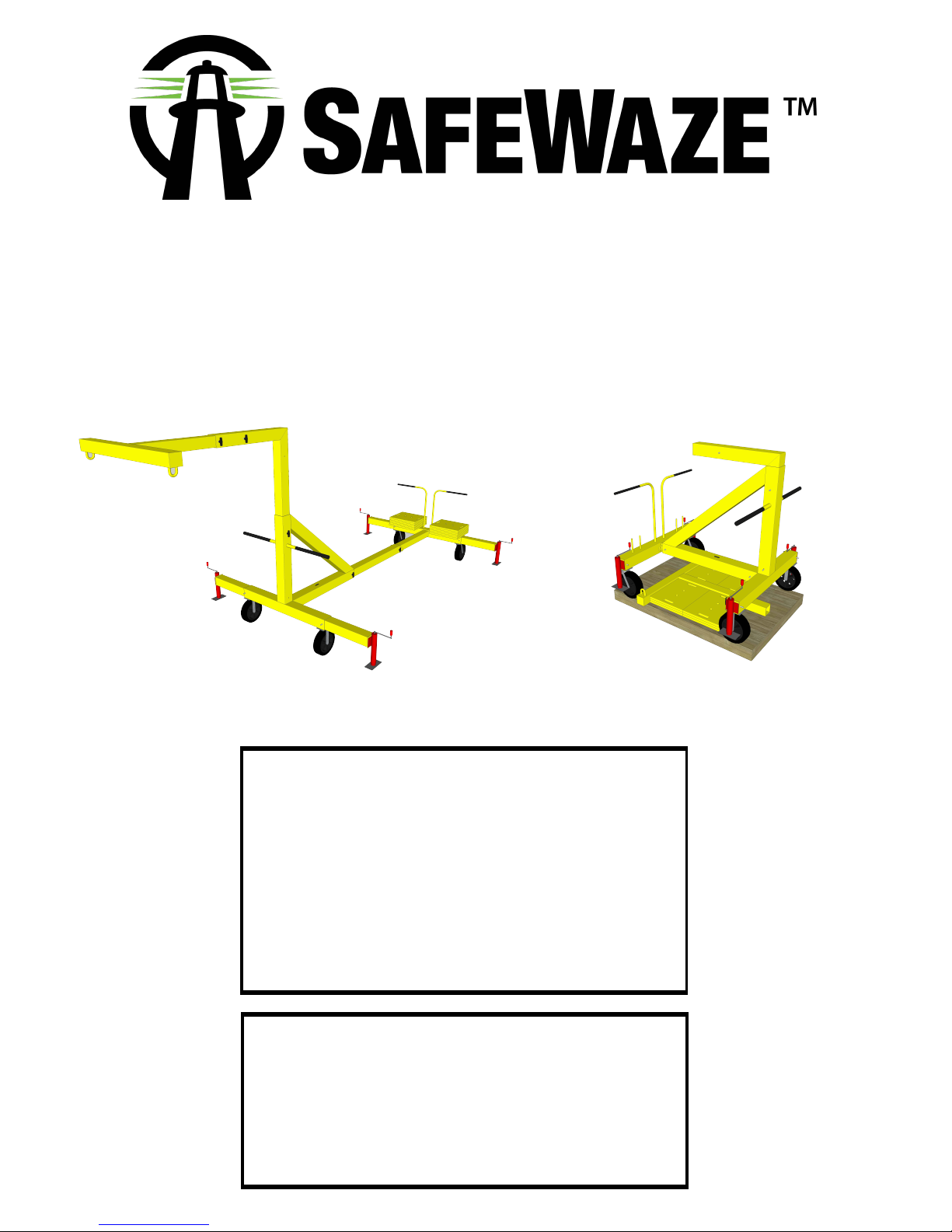
Precautions, Requirements & Exclusions
The integrity of Personal Fall Arrest Systems is only ensured if the user wears the
recommended personal protective equipment (PPE). This should be certified and marked in
accordance with the relevant national standard. Using the wrong PPE or SRLs/lanyards of
incorrect length can result in injury or death. Each System installed should be supplied with
specifications of a full body harness, lanyards, and shock absorbing device. See the System
Data Boxes on the System drawings for this specification. The following precautions,
requirements and exclusions apply to the fall protection equipment provided by Hy‐Safe
Technology:
•A recorded inspection must be conducted at least once a year by SAFEWAZE™ or a
Manufacturer’s Certified Installer.
•The systems must not be used for lifting.
•Do not use the systems for equipment or material tie back.
•Never exceed the recommended number of users on the systems (see the System Data Boxes on
the system drawings, or the System Tags attached to the systems).
•Never attempt to repair, tamper with or change the systems.
•Do not use the systems if they appear to be damaged or appear to have parts missing.
•Fall protection equipment should not be used outside of its limitations, nor shall it be used for any
other purpose than that intended.
•Each user should weigh no more than the maximum rated load for the energy absorbing lanyard/
SRL. The lanyard shall be capable of limiting the fall arrest load to less than 1800 lbs., and the
SRL shall be capable of limiting the fall arrest load to less than 900 lbs., per OSHA and ANSI
regulations.
•DO NOT attempt to clean the systems with aggressive cleaning chemicals and abrasive products.
•DO NOT use external fall protection systems in the event of an electrical storm.
•Only personnel trained to work at height and in the correct operation of the systems should be
permitted to use them.
•In the unlikely event that a fall does occur, the affected system(s) should not be used until they
have been inspected by SAFEWAZE™ or a Manufacturer’s Certified Installer.
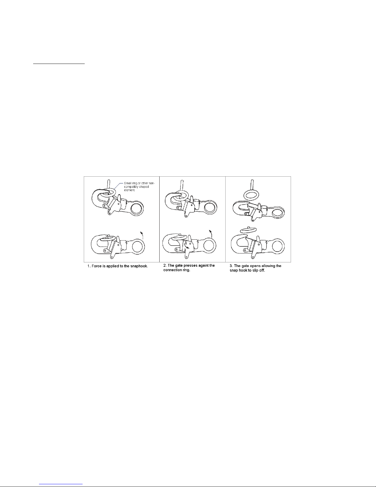
•If a lifeline cable is damaged or kinked, do not use the lifeline system.
•Take care when using the systems around moving machinery and electrical hazards.
•Sharp edges and abrasive surfaces can cause damage to PPE. Take care when using the
systems where these conditions exist. If PPE becomes damaged it must be taken out of service.
Although the system are made from corrosion resistant materials, solutions containing acids,
alkali, or other caustic chemicals, especially at elevated temperatures, may cause damage to the
systems. When working with such chemicals, frequent inspection of the systems must be
performed.
THE SYSTEM MUST BE FULLY DEPLOYED AND TELESCOPED OUT WITH SYSTEM LEVEL
AND WHEELS OFF THE GROUND COMPLETELY LIFTED BY THE LEVELING JACKS.
ALL PINS MUST BE INSERTED IN THE PROPER LOCATIONS OUTLINED IN THE SET-UP
DETAILS BELOW.

Pre‐Use Checks & In Use Checks
Personal Protective Equipment (PPE)
Equipment should be certified and marked to the appropriate national standard. Always
refer to the manufacturer’s instructions for use. Always wear a full body harness. Examine
harnesses, lanyards, self‐retracting lifelines or controlled rate descent devices in accordance
with their manufacturer’s instructions to ascertain if they are serviceable. If in doubt, do not
use them. If these items have been subjected to a fall, they must be serviced or discarded.
When not in use, these articles need to be stored in a clean, cool, dry area, free from chemical
fumes or corrosive elements. Direct sunlight, heat, steam, undue vibration and sharp
implements must also be avoided. Preferably, fall arrest equipment like this should, when not in
use, be kept in dedicated cabinets which permit adequate ventilation.
System Label
Prior to accessing the systems, the user should always inspect the System Tag in order to
confirm:
•The maximum number of users is not exceeded
•The System certificate is valid. The System should be certified yearly. If this has not
been done the user should not use the system.
System
Before attaching to the systems, carry out a visual inspection. Check that there are no obvious
signs of damage to the systems, such as breaks, kinks, excessive sag in a lifeline cable, or
damage to any components of any of the systems. If slip indicators are present, check that they
have not pulled away from the end termination components. Check the legibility of all markings
on any part of the systems and the users’ PPE.
If any of the above is questionable do not use the System and report to SAFEWAZE™.

Personal Protection Equipment (PPE)
It is of utmost importance in the design of
personal fall arrest systems to understand
the nature and type of work being performed
in an area prior to the installation of fall
protection equipment. Anchorages should
be located such that they are directly
overhead (or as much so as possible) to
help reduce or eliminate the possibility of a
swing fall. Separate anchorages must be
provided for each individual worker in an
area, and only one worker should be
attached to an anchorage at any one time. If
several workers are to be in an area at a
given time, the anchorages should be
placed so that the potential for entangling
the vertical lifelines is minimal.
Care should also be used in selecting a
harness. Harnesses with sewn down back
pads can limit as much as 1 ft. of back pad
slippage during fall arrest, giving additional
safety. If the system will be used where a
worker could encounter a head first free-fall,
a non-secured back pad can slide down the
webbing to the small of the back, allowing
the worker to fall out of the harness through
the top by allowing the harness straps to slip
over the shoulders. For this reason, we
recommend the use of full body, crossover or
pullover type harness with sewn down back
pads for all installations. The use of body
belts as fall arrest anchorages is not allowed
under OSHA guidelines.

Accessing and Using a Single Point Anchor
A. User Equipment
Always wear a full body harness for fall arrest. The user should attach their fall arrest device (lanyard,
SRL, or another device as directed and approved by SAFEWAZE™ ) to the back d-ring of the harness.
This prevents the lanyard getting in the way during movement and, in the event of a fall, ensures
minimum trauma to the user.
If the anchor is being used for fall restraint or work positioning, a body belt may be worn by the user.
The lanyard or attachment device should be attached to one of the side d-rings of the belt. A full body
harness may be worn for fall restraint or work positioning as well, and the harness may be equipped
with side d-rings. If it is, these may be attached to for this type of work.
Always ensure that the locking mechanism of the snap hook or karabiner is properly closed and
incapable of accidental disconnection to do roll-out or wear before proceeding, and get a second
person to check the attachment.
FIGURE 1 – UNINTENTIONAL DISENGAGEMENT (ROLL-OUT)
Always check for connection compatibility. Never make any connection that could result in a dangerous or fatal
condition. Snap hooks and karabiners should not be connected to the d-ring in the following manner:
A. To a d-ring to which another connector is attached
B. In a manner that would result in a load on the gate
C. In a false engagement, where protruding features catch on the anchor
D. To each other
E. Directly to webbing, rope lanyard, or tie-back
F. To any object which is shaped such that the connector will not close
and lock

Always check all PPE and equipment before attaching to the fall protection or performing any work, to
ensure that all components are in working order and free from defects or damage. If any defects or
damage is noted, the equipment should not be used and SAFEWAZE™ should be notified for
assessment and repairs.
B. Accessing the Single Point Anchor
Access to the anchor should be gained from a position of safety, removed from any fall hazards. If
necessary, the user should use other safety equipment, such as a lift or a guardrail system, to facilitate
safe access to the attachment area.
Anchor points for user attachment can vary from fabrication to fabrication, and the anchor point(s) for
your project will be indicated and demonstrated during the system training at the completion of the
installation. The typical attachment between a user and a single point anchor that is mounted overhead
is via a self-retracting lifeline (SRL). The SRL is attached to the d-ring using a karabiner. The typical
attachment between a user and a single point anchor that is located at the height of the user or lower is
via a lanyard (See Figure 3 below for an example using a d-ring), which should have a built-in shock
absorber for fall arrest applications, and may not have one for fall restraint applications. The lanyard is
attached to the anchor using the snap hook at the end of the lanyard that does not contain the shock
absorber (if applicable). If another type of attachment between the anchor and the user is used, contact
SAFEWAZE™ for instructions for attaching to the specific device.
For an overhead application, if the self-retracting lifeline (SRL) is not connected to the anchor, it will
need to be connected before the anchor can be used. Attaching the SRL to the anchor should be done
from a position of safety, removed from any fall hazards. To attach the SRL to the anchor, open the
gate of the karabiner on the top of the SRL housing and clip the karabiner onto the anchor. Allow the
gate to close onto the anchor, and check the connection to be sure it is secure and that accidental roll-
out cannot occur (see Figure 1 above).
FIGURE 2 – CONNECTING AN SRL TO AN ANCHOR

FIGURE 3 – CONNECTING A LANYARD TO AN ANCHOR
C. Attaching to the Single Point Anchor
As stated above, anchor points for user attachment can vary from fabrication to fabrication, and the
anchor point(s) for your project will be indicated and demonstrated during the system training at the
completion of the installation.
If an SRL is used, then a tag line attached to the SRL snap hook can be used. The cable or webbing
that is inside the housing of the SRL should not left extended from the unit when it is not in use, as this
can cause damage to the retracting or braking units inside the device. When returning the cable or
webbing to the device, it should be done slowly. The user must not simply release or let go of the snap
hook so that the device retracts too fast, as this may cause damage to the retracting or braking units
which may cause the device to not function properly in a fall arrest scenario. For further information,
refer to the “Self Retracting Lifeline Instruction Guide” in the operation and maintenance manual.
To attach to the SRL, pull the tag line down. This will pull the SRL snap hook down to you. Slip the tag
line knot off of the SRL snap hook, and secure the tag line in a convenient location within reach of the
system access location so it can be re-attached to the SRL when leaving the system. Once the user
has the snap hook, open the gate and clip the snap hook onto the back d-ring of the harness. If the
user is using a d-ring extender, open the snap hook and clip it onto the d-ring at the end of the
extender. Release the gate locks to allow the snap hook to grab onto the harness or d-ring extender d-
ring. Check the connection, or have another user check the connection for you, to be sure that it is firm
and that roll-out is not possible (see Figure 1 above). Allow the SRL cable or webbing to retract back
into the housing, guiding it slowly with the user’s hands. Once the slack has been taken out of the SRL
cable or webbing and it ceases retracting into the housing, work may commence.
FIGURE 4 – CONNECTING TO THE SRL

If a lanyard is used, once the lanyard has been secured to the d-ring (see Figure 3 above), attach the
snap hook at the end of the lanyard nearest the shock absorber (if applicable) to the back d-ring of the
harness or the side d-ring of the body belt or harness (see section A – User Equipment above). Check
the connection, or have another user check the connection for you, to be sure that it is firm and that roll-
out is not possible (see Figure 1 above). If a d-ring extender is used (the extender is connected to the
back d-ring of the harness), attach the snap hook at the end of the lanyard nearest the shock absorber
to the d-ring at the end of the extender. Check the connection, or have another user check the
connection for you, to be sure that it is firm and that roll-out is not possible (see Figure 1 above). Once
the lanyard has been secured to the single point anchor and to the user, work may commence.
FIGURE 5 – CONNECTING TO THE LANYARD

System Limitations
System Capacity
Body Telescoping Handles
Installation Distance
Working Angle
Installation Surface
Roof or Floor Structure
Moving the System
Workers - 2 workers
1 worker per anchor attachment
Each worker weighing a max of 310 lbs. with tools
Handles on the lower body of the roof reach are only to be
used for telescoping and retracting the unit.
The Roof Reach must have a minimum installation distance
from the front of the unit to the leading edge of at least 2.5 ft.
Minimum installation distance from the side of the unit to the
leading edge is 3 ft.
Anchorage loading is designed such that the angle between the
overhead single point attachment on the Roof Reach to the worker
must not exceed 30 degrees from vertical.
The unit must sit on clean and dry surfaces which result in the
proper friction needed.
Roof or floor structure must be capable of supporting the weight
of the unit and loading that will be seen in the event of a fall.
Never remain connected to the system while attempting to move
the unit. Move the unit by using the handles on the front and back
of the unit. Never expose a worker to a potential fall hazard
during movement of the system.

Part numbers and Assembly Identification
6.
7.
THE UNIT MUST SIT ON A CLEAN AND DRY SURFACE.
FRONT JACK FEET SHOUD BE AT LEAST 1 FOOT FROM
ROOF EDGE.

Step 1
Remove unit, weights, and arm assembly from skid.
Step 2
Remove upper and lower pins from front of body
front assembly, and set one pin aside. Remove
mast assembly from body front assembly, and
rotate 180 degrees so horizontal arm is facing
away from the body front assembly.
Step 3
Insert the arm assembly into the mast assembly,
aligning the holes in the back of the arm assembly
with the holes in the front of the mast assembly, and
pin in place with two pins. Step 4
Raise mast assembly until the hole in the bottom of
the mast assembly lines up with the top hole of the
body front assembly, and pin in place using one pin.
Step 5
Remove the two pins on the bottom of the
body front assembly. This will release the body
telescoping central section and the body rear
assembly, allowing these to be slide out from
the body front assembly.
Roof Reach Assembly Instructions

Roof Reach Assembly Instructions Continued
Step 6
Align the hole in the front and the back of the body telescoping central section with the hole in the back
and front of the body front and rear assembly, and pin in place using one pin.
Step 7
Pull pins from body front and body rear assembly at the wheels and telescope outriggers out until the far
holes on the outriggers line up with holes on front and back body assembly near wheels on each side. Pin
in this area and do not deploy jacks on the outriggers until the unit is in position and ready to be used.

Roof Reach Assembly Instructions Continued
Step 8
Place the counterweight plates onto the round
receivers on the back of the body rear
assembly (beneath the handles). Six weights
should be placed on each side, and all 12
weights must be used.
Step 9
Four workers may then push the unit into position.
Once in position, deploy all four leveling jacks until
the wheels of the unit are off the surface. Using
the level located on the body front assembly, make
sure the unit is level.
Step 10
Attach SRLs to the loop connections at the end of the
arm with double locking carabiners.
Attach SRL snap hook to the back D-ring of the workers
properly fitted full body harness.
!! WARNING !! WHEN CONNECTED TO THE ROOF REACH
IT MUST BE FULLY SET-UP AS INSTRUCTED ABOVE AND
ALL 4 JACKS MUST BE DEPLOYED WITH THE SYSTEM
LEVEL TO ENSURE ALL WHEELS ARE OFF OF THE
GROUND.

Product Specifications
Specifications
Compliance: Meets or exceeds all ANSI standards and OSHA 1926.502 regulations.
Warning: Failure to read and follow product instructions could result in serious personal injury
or death. Training and instruction review should be repeated at regular intervals. This
product must be used in strict compliance with local, state, and federal OSHA regulations.

Product Labels
Attention labels located on the Arm of the Roof
Reach system.
Deployment warning located on the body of the
Roof Reach system.
Counterweight warning located on the back of
the unit between the pushing handles.

Contact Information
SAFEWAZE™
322 Industrial Court
Concord, NC 28025
Phone: (704) 262-7893
Fax: (262) 262-9051
Email: [email protected]
www.safewaze.com

Inspection, Maintenance, and Servicing
A. Inspection and General Maintenance
SAFEWAZE™ fall protection systems have been designed to be used under a variety of
conditions. They use high‐grade components that are corrosion resistant. However, the working
life of the systems depends on factors such as correct care and maintenance and the environment
in which the systems are installed. Before each occasion of use a visual check must be conducted
to ensure a fall protection system is fit for purpose, whether the system is designed for fall arrest
or fall restraint. If a system is deformed in a way which is uncharacteristic of the system, you
should not use it. Red‐tag and discontinue the use of the system. Report the fault(s) to
SAFEWAZE™ and schedule a maintenance visit.
DO NOT attempt to repair the systems yourself, as this invalidates performance warranties and
can put personnel in danger.
The fall protection systems are virtually maintenance free depending on the environment.
Occasionally the systems may need cleaning. This should be done with a soft brush, warm water
and a mild detergent. Ensure that the parts are rinsed thoroughly with plenty of clean water.
Although highly resistant to chemicals and environmental conditions, take all precautions to avoid
contaminating the systems with acids, bitumen, cement, chloride, paint, or aggressive cleaning
fluids.
Stainless steel parts are particularly susceptible to pitting corrosion from chlorine, so avoid
exposure in this type of environment.
B. Servicing
In accordance with manufacturer’s recommendations and current national standards, systems that
are in regular use should be inspected at least once a year by SAFEWAZE™ or a Manufacturer’s
Certified Installer. In very high use applications or aggressive environments, the servicing interval
should be more frequent. The systems can have many unique features, which may not be readily
apparent; therefore only SAFEWAZE™ or Manufacturer’s Certified Installers should inspect these
products.
If a system has sustained a fall arrest impact, has be damaged, or is defective in any way, it must
be immediately categorized as unfit for use. The use of the system(s) must be discontinued, and
servicing should be arranged as soon as possible. All servicing requirements should be directed to
SAFEWAZE™ or a Manufacturer’s Certified Installer.

5.
6.
Inspect synthetic harnesses and lanyards for cuts, fraying fluffing, and chemical wear in
addition to checking for discoloration, damaged stitching, and exposed warning labels.
Inspect all labels to ensure that the Personal Fall Protection equipment has been
inspected by a Competent Person. Labels must be readable at all times.
INSPECTION LOG
Manufacturer: Model
No: Mfg. Date:
SAFEWAZE™ 704-262-7893
Date Condition of System Inspected By
Maintenance:
1. Inspect all hardware for distortion and deformation. Check for visible cracks, excessive wear and
tear, corrosion and chemical erosion. Also, remove hardware if there are sharp edges.
2. Inspect anchor points for physical damage, wear or corrosion that could affect their function in the
event of a fall.
3. Inspect carabineers and snap hooks to ensure that gate operates properly.
4. Inspect all hardware for correct operation, broken or missing pieces, and loose or missing items.
Table of contents
Popular Construction Equipment manuals by other brands

Minnich
Minnich THE HORNET 36/40 Operators & service manual

MetalTech
MetalTech I-CIS04 OPERATIONAL SAFETY AND ASSEMBLY INSTRUCTIONS

Peri
Peri CB 160 Instructions for assembly and use

HYVA
HYVA HB80 WARNING, OPERATING AND MAINTENANCE MANUAL

Ulma
Ulma TFS100 manual

Milwaukee
Milwaukee MXF CVBC Original instructions