SafeWaze 019-12001 User manual

User Manual
V1.7 2021 Copyright SafeWaze
LADDER CLIMB SYSTEM
USER INSTRUCTIONS
Compliant with OSHA CFR 29 1910.66, OSHA 1926.502
ANSI Z359.1, ANSI A14.3
2051

User Manual
V1.7 2021 Copyright SafeWaze Page 1
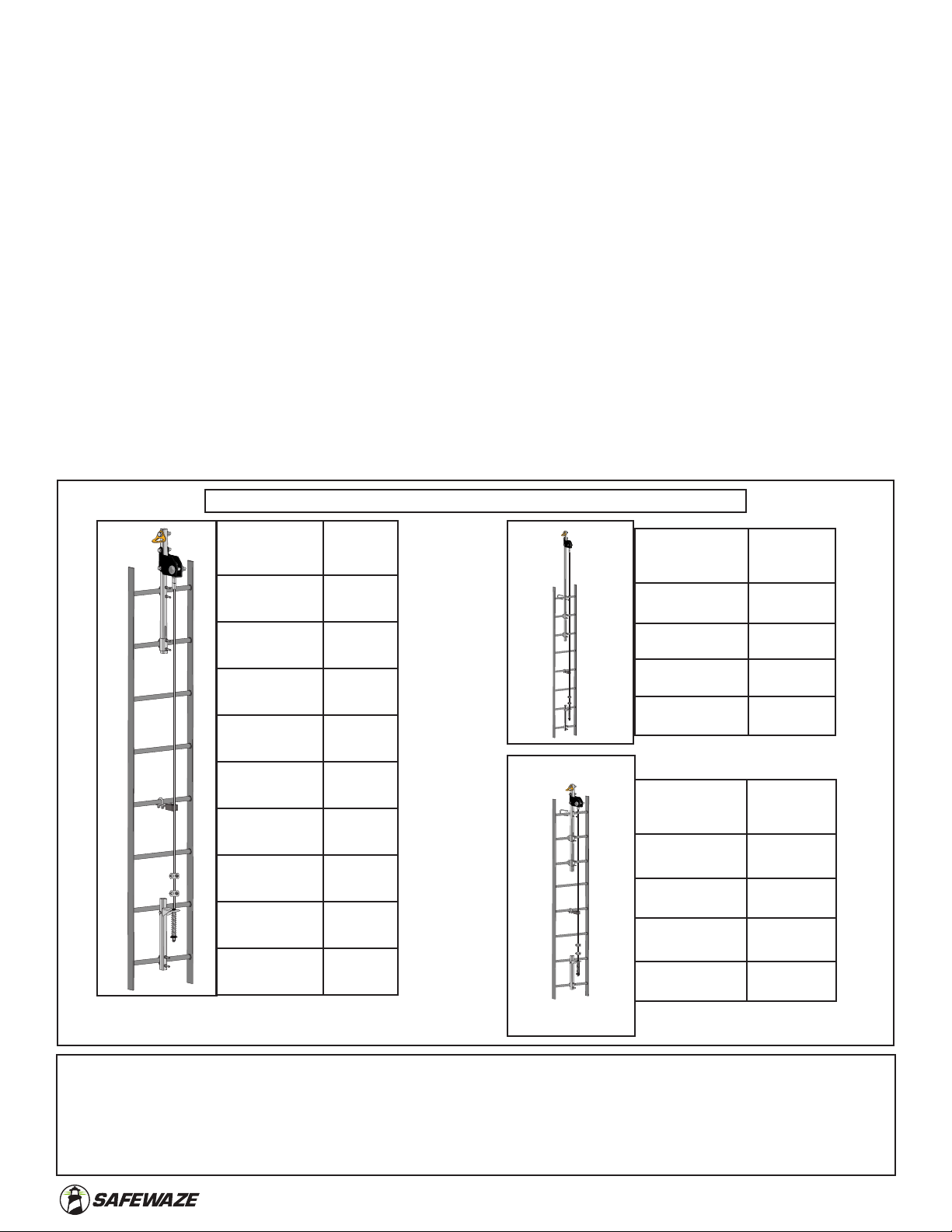
This product is part of a complete fall protection system. User’s must utilize, and connect to the Safewaze
Ladder Climb System with ANSI Z359 compliant restraint or Personal Fall Arrest Systems (PFAS). This product is
not designed, nor should be used as a component for a Postioning, Suspension, or Restraint. A PFAS is typically
composed of a Full Body Harness, Anchorage, and a Connecting Device. Connecting Devices used with the
SafeWaze Ladder Climb System are Energy Absorbing Lanyards (EAL’s) or a Self Retracting Device (SRD). The
connection point to the FBH for use of a SafeWaze Ladder Climb System is the Sternal (Front) D-ring.
WARNING
These instructions must be provided to any person utilizing this equipment. The worker must read and understand
the manufacturer’s instructions for this, and all other components of the complete Fall Protection System. It is
expected that all personnel be fully trained in the safe installation and use of this equipment. These instructions
must be followed for the proper use, maintenance, and inspection of this equipment. These instructions must
be kept and made available to worker’s at all times. Any alteration, misuse, or use of this equipment outside the
scope of the manufacturer’s instructions, may result in serious injury or death. A comprehensive Fall Protection
Plan must be kept on le and available to all employees at all times.
Consult your doctor if there is reason to doubt your tness to safely absorb the shock from a fall arrest. Age
and tness seriously affect a worker’s ability to withstand falls. Pregnant women or minors must not use this
equipment. Failure to heed this warning may result in serious injury or death.
Never exceed the maximum allowable capacity of your fall protection equipment. Never exceed the maximum free
fall distance of your fall protection equipment.
Do not use this system or any other part of a PFAS that fails pre-use or other scheduled inspections. For any
questions or concerns regarding the use of this equipment, for an application not specied in this manual, contact
SafeWaze technical support.
Additional precautions should be used when working in environments of high heat, electrical hazards, chemical
hazards, explosive or combustible chemicals, toxic materials, sharp edges, or where equipment used above could
topple onto a user below, or their fall protection equipment.
Contact SafeWaze if you have questions, regarding compatibility of this equipment, that are not covered in this
manual. Do not alter or misuse this equipment. Some subsystem components could affect the performance and
the operation of this equipment. Do not anchor this product to moving machinery, or hazards that have chemical,
electrical or gaseous characteristics. Failure to comply with this warning could result in serious injury or death.
Use of a body belt for fall protection applications is not permitted. Only use an approved Full Body Harness.
Inspect all components of this system prior to to each use and at least annually. Inspect in accordance with the
user instructions. If this equipment is exposed to the forces of a Fall Arrest or Impact Force, the equipment must
be removed from service and inspected by a Competent Person prior to being used again.
Do not connect to the Ladder Climb System while it is being installed. When unpacking the cable assembly, ensure
that proper PPE is used as cable may rapidly uncoil when released from packing. Connections of a Full Body
Harness (FBH) to the system must be made with approved connections only. The cable assembly included with this
system, is the only cable constituent authorized for use with the system.
Personnel must always maintain 3 points of contact during climbing operations. If utilizing components from
different manufacturer’s, ensure that all components are compatible and meet all applicable standards, codes, and
requirements. Before using this equipment, consult with a Competent and/or Qualied Person.
Make considerations for eliminating or minimizing all swing fall hazards. Swing falls occur when the anchor is not
directly above the location where a fall occurs. Always work as close to in line with the anchor point as possible.
Swing falls signicantly increase the likelihood of serious injury or death in the event of a fall.

User Manual
V1.7 2021 Copyright SafeWaze Page 2
Table of Contents
1 INTRODUCTION & SCOPE OF USE............... 3
2 APPLICABLE SAFETY STANDARDS.............. 3
3 WORKER CLASSIFICATIONS......................... 3
4 PRODUCT SPECIFIC APPLICATIONS............ 3
5 LIMITATIONS.................................................... 4
6 COMPATIBILITY OF CONNECTIONS ............4-5
7 MAKING CONNECTIONS................................ 6
8 COMPONENTS AND SPECIFICATIONS........7-9
9 MATERIALS...................................................... 9
10 STRUCTURE LOAD REQUIREMENTS.......... 10
11 INSTALLATION..............................................11-19
12 SYSTEM USE................................................19-22
13 INSPECTION AND MAINTENANCE .............. 23
14 LABELS ........................................................... 24
15 INSPECTION LOG .......................................... 25

User Manual
V1.7 2021 Copyright SafeWaze Page 3
2.0 Applicable Safety Standards
Personal Fall Arrest: The SafeWaze Ladder Climb System can be used as part of a
complete Personal Fall Arrest System (PFAS) for a maximum of 4 users
(Part# 019-12024). The structure utilized for attachment must be capable of
withstanding a load of 5,000 lbs in all directions permitted by the system.
4.0 Product Specific Applications
3.0 Worker Classifications
Understand the denitions of those who work in proximity of or may be
exposed to fall hazards.
Qualied Person: A person with an accredidated degree or certication, and with
extensive experience or sucient professional standing, who is considered procient in
planning and reviewing the conformity of fall protection and rescue systems.
Competent Person: A highly trained and experienced person who is assigned by the
employer to be responsible for all elements of a fall safety program, including, but not
limited to, its regulation, management, and application. A person who is procient in
identifying existing and predictable hazards, and who has the authority to stop work in
order to eliminate hazards.
Authorized Person: A person who is assigned by their employer to work around or be
subject to potential or existing fall hazards.
It is the responsibility of a Qualied or Competent person to supervise the job
site and ensure safety regulations are complied with.
1.0 Introduction & Scope of Use
The SafeWaze Ladder Climb System is to be used as part of a Personal Fall Protection
System (PFAS). This Ladder System is designed to protect a worker(s) in the event of
a fall while ascending or decending a xed ladder or similar structure, with a compliant
wire rope fall arrester. The SafeWaze Ladder Climb System is intended to be installed
on xed ladders, or ladder like assemblies that are part of a structure (i.e., antenna
and tower structures, manways, buildings, and wood, steel, or concrete mono poles).
Always wear a Full Body Harness with a Sternal (Front) D-ring attachment point that
conforms with ANSI Z359.11 or relevant national standard.
ANSI Z359.0 Denitions and Nomenclature Used for Fall Protection and Fall Arrest
ANSI Z359.1 Safety Requirements for Personal Fall Arrest Systems, Subsystems, and Components
ANSI Z359.2 Minimum Requirements for a Comprehensive Managed Fall Protection Program
ANSI A14.3 American National Standard for Ladders - Fixed - Safety Requirements
ANSI STANDARDS
OSHA REGULATIONS
OSHA 1910.29 Fall Protection Systems and Falling Object Protection Criteria and Parctices
OSHA 1926.1053 Stairways and Ladders

User Manual
V1.7 2021 Copyright SafeWaze Page 4
Fall Clearance: There must be sucient clearance below the anchorage connector to
arrest a fall before the user strikes the ground or an obstruction. When calculating fall
clearance, account for a MINIMUM 2’ safety factor, deceleration distance, user height,
length of Lanyard/SRL, and all other applicable factors.
5.0 Limitations
The SafeWaze Ladder Climb System is not designed, nor intended, to be installed on
portable ladders. This system is designed for use on structures that primarily vertical.
The system should never be used on a structure that exceeds a 15° degree angle from
vertical.
Full Body Harnesses
Only Full Body Harnesses with a sternal (front) D-ring may be used with the Safewaze
Ladder Climb System.
Note: Never use combinations of components or subsystems that may aect, or
interfere with the safe function of each other.
Part
Number
Max
Users
019-12032 2
019-12034 2
019-12036 2
019-12038 2
Part
Number
Max
Users
019-12001 2
019-12002 2
019-12003 2
019-12004 2
019-12005 2
019-12006 2
019-12007 2
019-12008 2
019-12009 2
Part
Number
Max
Users
019-12041 4
019-12043 4
019-12045 4
019-12047 4
FIGURE 1 - MAX SYSTEM USER CAPACITY
**NOTE: Maximum User Ratings as indicated in these system charts require the use of an ANSI Z359.16 Cable Fall
Arreter. If a Cable Fall Arrester is used which does not meet the ANSI requirements, then all systems are limited to the
OSHA reqirements of Max. 1 user. The Number of Climbers (as dened by ANSI) for climbing Ladder Fall Arrest Systems
shall be designed for a minimum of 2 simulataneous users. This is necessary to facilitate rescue. The maximum number
of simultaneous users allowed on the system should be determined by a competent person based on the job site
conditions and any limitations set by the manufacturer.

User Manual
V1.7 2021 Copyright SafeWaze
FIGURE 2 - UNINTENTIONAL DISENGAGEMENT
Non-compliant part
3 - gate opens
2 - gate presses
against
non-complaint
part
4 - and parts disengage.
1 -
NOTE: SOME SPECIALITY CONNECTORS HAVE ADDITIONAL REQUIREMENTS.
CONTACT SAFEWAZE WITH QUESTIONS.
Using a connector that is undersized or irregular in shape (1) to connect a snap hook
or carabiner could allow the connector to force open the gate of the snap hook or
carabiner. When force is applied, the gate of the hook or carabiner presses against
the non-compliant part (2) and forces open the gate (3). This allows the snap hook or
carabiner to disengage (4) from the connection point.
Page 5
Connectors are compatible with connecting elements when they have been designed
to work together in such a way that their sizes and shapes do not cause their
gate mechanisms to inadvertently open regardless of how they become oriented.
Connectors (hooks, carabiners, and D-rings) must be capable of supporting at least
5,000 lbs. (22.2 kN). Connectors must be compatible with the anchorage or other
system components. Do not use equipment that is not compatible. Non-compatible
connectors may unintentionally disengage (See Figure 2). Connectors must be
compatible in size, shape, and strength. Self-locking snap hooks and carabiners are
required by ANSI Z359 and OSHA guidelines. Contact SafeWaze
if you have any questions about compatibility.
6.0 Compatibility Of Connections
The following limitations must be considered prior to installing the SafeWaze Ladder
Climb System:
1. Structure: The structure to which the system is attached must be capable of
withstanding the loads applied by the system in the event of a fall.
2. System Capacity: The maximum number of users allowed on the SafeWaze
Ladder Climb System simultaneously is 2, with a maximum weight of 310 lbs
per user (including clothing, tools, and equipment). System numbers
019-12041, 019-12043, 019-12045, and 019-12047 allow a maximum
number of 4 users with a maximum weight of 310 lbs per user.
3. Environmental Hazards: Use of the SafeWaze Ladder Climb System in
areas where environmental hazards exist may require additional precautions.
These hazards may consist of, but are not limited to: Electrical, Chemical,
Thermal,Seawater, Corrosive Agents, Explosive Gasses, Toxic Gasses,
Moving Machinery, and Sharp Edges.

User Manual
V1.7 2021 Copyright SafeWaze Page 6
7.0 Making Connections
Snap Hooks and Carabiners must be ANSI Z359.12 compliant with a double locking
gate. Ensure all connections are compatible in size, shape and strength. Do not use
equipment that is not compatible. Ensure all connectors are fully closed and locked.
SafeWaze connectors (snap hooks and carabiners) are designed to be used only
as specied in each product’s user’s instructions. See Figure 3 for examples of
inappropriate connections. Do not connect snap hooks and carabiners:
• To a D-ring to which another connector is attached.
• In a manner that would result in a load on the gate (with the exception of tie back
hooks).
• In a false engagement, where features that protrude from the snap hook or
carabiner catch on the anchor, and without visual conrmation seems to be fully
engaged to the anchor point.
• To each other.
• By wrapping the web lifeline around an anchor and securing to lifeline except as
allowed for Tie Back models.
• To any object which is shaped or sized in a way that the snap hook or carabiner will
not close and lock, or that roll-out could occur.
• In a manner that does not allow the connector to align properly while under load.
**NOTE: Large snap hooks must not be connected to objects which will result in a load on the gate if the hook twists
or rotates, unless the snap hook complies with ANSI Z359.1-2007 or ANSI Z359.12 and is equipped with a 3,600 lb
(16 kN) gate. Check the marking on your snap hook to verify its compatibility.
**NOTE: Large throat snap hooks must not be connected to standard size D-rings or similar objects which
will result in a load on the gate if the hook or D-ring twists or rotates, unless the snap hook complies with
ANSI Z359.1-2007 or ANSI Z359.12 and is equipped with a 3,600 lb (16 kN) gate. Check the marking on
your snap hook to verify that it is appropriate for your application.
FIGURE 3 - INAPPROPRIATE CONNECTIONS
The SafeWaze Ladder Climb System is designed for use with an ANSI Z359.16 3/8”
Wire Rope Grab. The use of any other type of grab may be incompatible with the
system, and could create a serious safety hazard for the user. Do not use the
SafeWaze Ladder Climb System without rst consulting with a Competent and/or
Qualied Person at the worksite for approval. For any other questions regarding
compatibility, please contact SafeWaze Technical Support
**NOTE: ANSI Z359.1-2007 Safety Requirements for Personal Fall Arrest Systems, Subsystems and Components,
requires a Competent Person and/or a Qualied Person to “ensure that systems assembled from components and
subsystems made by dierent manufacturers meet the requirements of the Standard.”

User Manual
V1.7 2021 Copyright SafeWaze Page 7
8.0 Components and Specifications
FIGURE 4 - LADDER CLIMB SYSTEM COMPONENTS
A
D
E
F
G
H
I
B
C
AAnchor Point
BTop Bracket
CBottom Bracket Assembly
DCable Attachment Point
ERung Clamps
FCable
GCable Stand-O
HCable Fist Grips
IRung Clamp

User Manual
V1.7 2021 Copyright SafeWaze
Complete System
Part Number
System
Length
Individual Cable
Assembly Part
Number
019-12001 20 ft.
Complete System
Part Number
System
Length
019-12032 30 ft.
019-12034 50 ft.
019-12036 70 ft.
019-12038 90 ft.
019-12002 30 ft.
019-12003 40 ft.
019-12004 50 ft.
019-12005 60 ft.
019-12006 70 ft.
019-12007 80 ft.
019-12008 90 ft.
019-12009 100 ft.
019-12012 20 ft.
019-12013 30 ft.
019-12014 40 ft.
019-12015 50 ft.
019-12016 60 ft. 019-12020 100 ft.
019-12021 Custom
019-12017 70 ft.
019-12018 80 ft.
019-12019 90 ft.
2 User Capacity
Complete System
Part Number
System
Length
019-12041 30 ft.
019-12043 50 ft.
019-12045 70 ft.
019-12047 90 ft.
4 User Capacity
2 User Capacity
(w/ 48” extension)
Page 8

User Manual
V1.7 2021 Copyright SafeWaze Page 9
9.0 Materials
Top and Bottom Bracket: Galvanized Steel and Stainless Steel
Cable Assembly: 3/8” 7x19 Galvanized Cable
Tensioner: Galvanized Steel Body, Stainless Steel Spring
Fist Grips: Drop Forged Steel, Hot Dipped Galvanized
Cable Stand-O’s: Galvanized Steel Harware, Synthetic Rubber Guide
SRD Attachment Point: Forged Steel (Painted)
Individual
Bottom Bracket
Part Number
(Compatible with all systems)
Max
User
Capacity
019-12025 4
Intermediate Guide (90°)
019-12026
Intermediate Guide
019-12027
Ladder System U-bolt
019-12028
Nuts (2 pc Set)
019-12029
VLL Ladder System
Backer Bracket
019-12030 VLL Ladder System Label
370-00004
VLL Ladder System
SafeWaze
Concord, NC 28025
(800) 230-0319
Installation Date
Max Users per System
(310 lbs per user)
Max Users per System
(420 lbs per user)
Anchorage Requirements
Installed By
= 2,700 lbs (12kN)
= 3,320 lbs (14.8kN)
= 3,940 lbs (17.5kN)
= 4,560 lbs (20.3kN)
019-12022 =
019-12023 =
019-12024 =
019-12022 =
019-12023 =
019-12024 =
System Length
Mfg. Date
Serial Number
JAN FEB MAR APR MAY JUN JUL AUG S EP OCT NOV DEC
Inspection Log
Failure to heed warnings related to this system may
result in serious injury or death. Manufacturer’s instructions supplied
with this product at time of shipment must be followed for proper
installation, use, inspection, and maintenance of this equipment.
Unauthorized alteration or substitution of components for this system is
prohibited. Use only with compatible personnel equipment authorized
per manufacturer’s instructions. System must be inspected prior to
each use, and at least annually by a competent person other than the
user. Annual inpsections should be documented in the inpsection grid
on this label, as well as the instruction manual. The climbing structure
to which this system is attached must also be inspected, in accordance
with its individual inspection criteria. Minimum spacing between user’s
of this system is 20 ft.
DO NOT REMOVE THIS LABEL
019768
Individual
Top Bracket
Part Number
Max
User
Cap
019-12022 2
Individual
Top Bracket
Part Number
Max
User
Cap
019-12023 2
Individual
Top Bracket
Part Number
Max
User
Cap
019-12024 4

User Manual
V1.7 2021 Copyright SafeWaze Page 10
10.0 Structure Load Requirements
The structure to which the Ladder Climb System is attached must be capable of
withstanding the total loads imposed by the system.
9.1 Static Loading: The static loads imposed on the system include the weight
of the top bracket, weight of the length of cable used with the system and a
Safety Factor. The following is an example of static loads imposed on the
system for a 50 ft (15.24 m) system:
Top Bracket Weight = 24 lbs (10.9 kg)
50 ft. (15.24 m) of 3/8” (9.5 mm) Galvanized Cable Weight = 13.25 lbs (6.01 kg)
Total Static Loading: (24 lbs + 13.25 lbs) x 1.2 (Safety Factor) = 47.3 lbs
9.2 Dynamic Loading: The following are the Dynamic Loads imposed onto the
Ladder Climb System per user:
One User = 2,700 lbs (12 kN)
Two Users = 3,320 lbs (14.76 kN)
Three Users = 3,940 lbs (17.51 kN)
Four Users = 4,560 lbs (20.27 kN)
9.3 Total Loading: The total load must account for the Static and Dynamic
Loading indicated above for the total length of the sytem. The following is
an example of the Total Loading imposed onto the structure given that the
example system is 50 ft (15.24 m) in length:
Static Loading for a 50 ft. (15.24 m) system = 47.3 lbs
Dynamic Load for Two Users = 3,320 lbs
Total Loading = 47.3 lbs + 3,320 lbs = 3,367.3 lbs
Total Loading of the system onto the attachment structure can be reduced by limiting
the number of user’s on the system.
Bottom Bracket Assembly: The bottom bracket assembly connection point
must be capable of supporting the system pretension load of 350 lbs (1.6 kN)
in the direction of loading. The required bracket load may be assumed to be
distributed evenly between the number of rung attachments for calculation
purposes.

User Manual
V1.7 2021 Copyright SafeWaze Page 11
The SafeWaze Ladder Climb System is designed for easy installation onto a variety of
suitable structures. For systems 50 ft. or greater in length, a cable stand-o must be
used. A cable stand-o must be used every 25 ft to 30 ft on systems greater than
50 ft in length.
As a general rule, the SafeWaze Ladder Climb System should be installed from the top
of the structure down.
Installation Steps:
Step 1: Install the Top Bracket onto the top two rungs of the ladder.
Step 2: Connect the cable to the Top Bracket
Step 3: Install the Cable Stand-O’s as necessary
Step 4: Install the Bottom Bracket Assembly
Step 5: Tension the Cable
Step 6: Inspect the Installation
Installation time can be reduced, and safety increased, by pre-planning the installation
process.
The entire Safewaze Ladder Climb System, and its subsystems, must be inspected
prior to each use for wear, damage, and other deterioration. All snaphooks and
carabiners must be able to self-close and lock. System must be properly tensioned.
No load indicators shall be deployed (See Figure 13, page 20). Damaged and other
deteriorated and defective components must be immediately removed from service,
in accordance with the requirements of OSHA 29 CFR 1910.66 and 1926.502.
In order to begin installation of the SafeWaze Ladder Climb System the installer needs
to know the part numbers of the system, the number of Stand-O’s required, and
length of the cable assembly. Inspect all components of the system prior to beginning
installation to ensure no damge occurred during shipping. In the event any damage is
discovered during the pre-installation inspection, contact SafeWaze for replacement
guidance.
Before Each Use
Users of personal fall arrest systems must have a rescue plan in place, if the user
cannot rescue themselves, as well as the means to carry out the rescue.
The user must read and understand these User Instructions, as well as the User
Instructions for every component/subsystem of the personal fall arrest system.
11.0 Installation
Installation of the SafeWaze Ladder Climb System must be supervised by a Qualied
Person.

User Manual
V1.7 2021 Copyright SafeWaze Page 12
Step 1: Installation of Top Bracket
Prior to installation of the Top Bracket, a Qualied Person should determine that the
structure is capable of meeting the load requirements of the system. Ensure that the
Top Bracket is positioned to allow users safe access when connecting or disconnecting
from the system. As a general rule, the Top Bracket is centered on the climbing
structure to allow for ease of climbing. However, the bracket may be installed
towards the side of the structure if necessary (See Section 10).
Two User Capacity Top Bracket - Part# 019-12022 (Figure 5A): Line up the
pre-drilled holes on the bracket with the top rung of the climbing structure. Slide the
upper rung clamp over the back of the rung and through the two pre-drilled holes in the
bracket. Thread nuts onto the rung clamps and torque to 20-25 ft. lbs. The Top Bracket
includes a pre-cut slot for adjustment to align the lower rung clamp with the lower rung.
Position the lower rung clamp on the lower rung using the pre-cut slot, install the nuts
onto the clamp, and torque to 20-25 ft. lbs.
Four User Capacity Top Bracket - Part# 019-12024 (Figure 5B): Line up the
pre-drilled holes on the bracket with the top rung of the climbing structure. Slide the
upper rung clamp over the back of the rung and through the two pre-drilled holes in the
bracket. Thread nuts onto the rung clamps and torque to 20-25 ft. lbs. The Top
Bracket includes pre-cut slots for adjustment to align the middle and lower rung clamps
with their corresponding rungs. Position the middle and lower rung clamps on the
rungs,install the nuts onto the clamps, and torque to 20-25 ft. lbs.
Two User Capacity Top Bracket with 48” Extension - Part# 019-12023 (Figure 5C):
Line up the pre-drilled holes on the bracket with the top rung of the climbing structure.
Slide the upper rung clamp over the back of the rung and through the two pre-drilled
holes in the bracket. Thread nuts onto the rung clamps and torque to 20-25 ft. lbs. The
Top Bracket includes pre-cut slots for adjustment to align the middle and lower rung
clamps with their corresponding rungs. Position the middle and lower rung clamps on
the rungs,install the nuts onto the clamps, and torque to 20-25 ft. lbs.

User Manual
V1.7 2021 Copyright SafeWaze Page 13
FIGURE 5 - TOP BRACKET INSTALLATION
Lower Rung
Clamp
Slot for
Adjustment
Pre-Drilled
Holes
Upper Rung
Clamp
Upper Rung
Clamp
Middle Rung
Clamp
Slot for
Adjustment
Slot for
Adjustment
Lower Rung
Clamp
Two User Capacity
Top Bracket Installation
Four User Capacity
Top Bracket Installation
A
B
Part # 019-12022
Part # 019-12024
Pre-Drilled
Holes

User Manual
V1.7 2021 Copyright SafeWaze
Upper Rung
Clamp
Middle Rung
Clamp
Slot for
Adjustment
Slot for
Adjustment
Lower Rung
Clamp
Two User Capacity
Top Bracket Installation
With 48” Extension
C
Part # 019-12023
Pre-Drilled
Holes
Rung Spacing and Diameter Compatibility:
Spacing 9” - 12.25” (200mm - 310mm)
Cylindrical Rung 0.5” - 1.6” (13mm-40mm) diameter
Square Rung 0.5” - 1.6” (13mm-40mm) diameter
Diamond Rung 0.5” - 1.6” (13mm-40mm) height
Angle Iron 0.5” - 1.6” (13mm-40mm) leg height
Rectangular Rung 0.5” - 1.6” (13mm-40mm) height, 0.5” - 1.9” (13mm-48mm) width
Page 14

User Manual
V1.7 2021 Copyright SafeWaze Page 15
Step 2: Connect the Cable to the Top Bracket
Prior to connecting the Cable Asembly to the Top Bracket, take the cable and uncoil it
on ground in a clean area and inspect for any damage. If any shipping damage is found
on the Cable Assembly, DO NOT USE.
To connect the cable to the Ladder Climb System, rst remove the Cable Connection
Bolt from the Top Bracket Assembly (See Figure 6A). Insert the thimble end of
the cable through the pre-cut slot in the bottom of the Top Bracket Assembly
(See Figure 6A). Align the thimble end of the Cable Assembly within the Top Bracket
and re-insert the Cable Connection Bolt through the Top Bracket and the thimble end
of cable. Thread nut onto the Cable Connection Bolt and tighten to 40 to 45 ft-lbs
(See Figure 6B & 6C).
Step 3: Install Cable Stand-O’s
The Ladder Climb System Cable Stand-O’s are designed to prevent abrasion of the
Cable Assembly on ladder rungs and to prevent excessive movement of the cable from
side to side while the user is climbing. They can also be used if high winds are
prevalent at the structure location to reduce harmonic vibration on the cable assembly.
The Stand-O’s should be installed every 25-30 ft. along the cable between the Top
and Bottom Brackets. See Figure 7A & 7B for typical installation. In instances where
high winds may be prevalent, Stand-O’s that are oriented in an “L” shape can be
installed. The “L” type Stand-O’s should be installed in a interval orientation to the
cable (left and right) as the example indicates in Figures 7C & 7D.
FIGURE 6 - CONNECT CABLE TO TOP BRACKET
A B C

User Manual
V1.7 2021 Copyright SafeWaze Page 16
Ladder Rung
Ladder Rung
FIGURE 7 - INSTALL CABLE STAND-OFF’S
A B
D
Installation (Side View) Installation
(As installed on rung)
Installation
(As installed on rung)
Ladder Rung
Ladder Rung
CInstallation (Side View)
Part# 019-12027
Part# 019-12028

User Manual
V1.7 2021 Copyright SafeWaze Page 17
Step 4: Install Bottom Bracket Assembly
Align pre-drilled holes on the bracket with the bottom rung of the climbing structure.
Slide the rung clamp over the back of the rung and through the two pre-drilled holes in
the bracket (See Figure 8). Thread nuts onto the rung clamp. Tighten the rung clamp to
20-25 ft-lbs.
FIGURE 8 - BOTTOM BRACKET INSTALLATION
FIGURE 9 - ATTACH CABLE TO TENSIONER ASSEMBLY
Step 5: Tension the Cable
Loosen the cable st grips to attach the cable assembly to the tensioner rod on the
Bottom Bracket assembly. Insert cable through st grips, remove excess slack from
the system by hand, but do not yet fully re-tighten st grips (See Figure 9A & 9B).
A B
Fist Grip Fist Grip
Fist Grip
Cable Tensioner
Rod
Tensioner
Rod
Rung Clamp

User Manual
V1.7 2021 Copyright SafeWaze Page 18
Slide washer (a) onto tensioning assembly. Thread the tensioning nut (b) onto
tensioner until approximately 3 to 5 threads are exposed below the nut (See Figure 10
- Step 1). Pull up on Tension Assembly until washer (a) contacts bottom of spring.
Ensure excess cable slack is again removed from system and torque st grips to
35 ft-lbs. (See Figure 10 - Step 2). Tighten tensioning nut (b) on tensioner until 1/2” of
tension indicator (d) is visible or cable is taut. Tighten locking nut (c) until snug to
tensioning nut (b). Cut excess slack o end of cable (e) (See Figure 10 - Step 3).
a
a
b
b
b
c
c
c
3-5 Threads Left
Exposed
FIGURE 10 - TENSION THE CABLE
Step 1 Step 2 Step 3
d
e

User Manual
V1.7 2021 Copyright SafeWaze Page 19
12.0 System Use
After installation, labeling, and inpsection of the system as dened in Section 12.0, the
SafeWaze Ladder Climb System is ready for use.
User’s of this system must be trained in it’s use, and must read and understand all
instructions provided with the system at time of shipment.
PPE must be utilized by all user’s. This should include, but is not limited to, eye
protection, hard hat, appropriate footwear, gloves, and any other equipment deemed
necessary by the Competent Person onsite.
A Full Body Harness (FBH) equipped with a Sternal (Front) D-ring, is required for use
of this system.
A 3/8” wire-rope grab is required in order to safely uitize the system.
Attach the 3/8” wire-rope grab to the cable assembly prior to beginning any climing of
the structure.
Once attached to the cable assembly, the user can begin climbing the structure. The
user should always ensure that the wire-rope grab is as high as possible on the cable
assembly, relative to their body position.
Step 6: Inspect the Installation
Ax the installation and inspection label in a prominent location on the structure (See
Section 14 for example Labels).
Before installing the label mark the following:
- Installation Date
- Installer
- Maximum Number of Users per system
- System Length
After installation, the installer must inspect the system as follows:
- Ensure all fasteners are torqued to proper levels as per instructions
- Verify proper tension of the cable assembly and connection to bottom bracket
- Ensure all cable assembly components are installed as per instructions
- Visually inspect the cable assembly to conrm it does not abrade at any point
on climbing structure
- Conrm that the system information is recorded on the label
This manual suits for next models
16
Table of contents
Popular Ladder manuals by other brands

Profi-Partner
Profi-Partner 49461 Instructions for use and Safety Instructions

AmazonBasics
AmazonBasics B07WJWRDFW quick start guide

Roto
Roto Columbus profiLine F30 installation instructions

Bilco
Bilco BL-Z Installation

Sealey
Sealey LAD004 quick start guide

Werner
Werner Telescopic Extension Ladder Series instruction manual