Safire cera22 User manual

1 / 8
Safire cera22 Ceramic cooktop
SF-Lämmitin Oy Tilhenkatu 1 20610 TURKU, FINLAND Tel. +358(0)2 244 3282 www.safire.fi 01/2018
CONTENTS OF THE FACTORY PACKAGING:
- cera22 Ceramic cooktop, fasteners
- Fuel line (approx. 3m), pump
- Power cables (approx. 4m)
- Sirius control panel (approx. 2m cable)
INSTALLATION
INSTALLATION LOCATION
- Provide ventilation at the installation location so that as the cooktop heats up, a natural air
circulation is created to provide ventilation. If necessary, exhaust air can be led directly
through the table top by using a ventilation grille for table tops.
- There must not be any material above the cooktop that presents a fire hazard in the event of
the cooktop overheating.
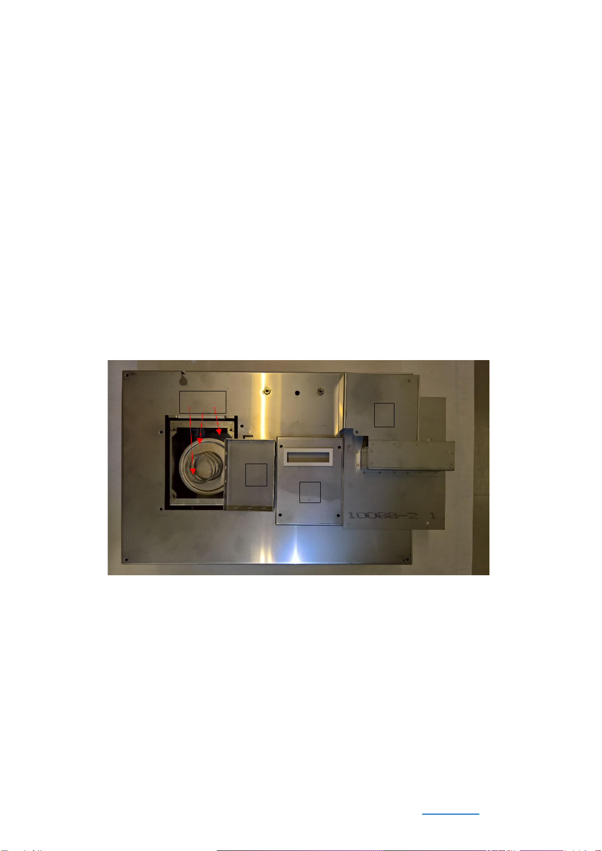
- You should be able to remove the hob for maintenance work. Some maintenance work (glow
plug, feed needle and flame sensor) and attachments can be done through a service hatch
located in front of the cooktop.
- Install the control panel in a place convenient for usage (visibility and use of controls),
preferably on a vertical surface.
- The cooktop heats its surroundings. This should be taken into consideration when choosing
the location of the refrigerator and the cooktop, for example.
INSTALLATION
- Saw a 443 x 300 mm mounting opening (height 200 mm) on the table top.
- Ensure ventilation underneath the cooktop by providing ventilation openings of approximately
100 cm2(=10x10cm) on the top and bottom of the installation space.
- Before mounting the cooktop, it is recommended to install the flue gas pipe (max. 3.5m).
- Mark the centre of the flue gas pipe, but ensure that there is enough space inside the upward-
pointing “goose neck” that prevents water from entering the flue gas pipe. The outlet of the
flue gas pipe must be located either at the rear of the side of the boat or in the stern at least
0.5m from the refuelling connection and the sea level.
- Drill a 30mm hole to the boat’s structure and 4.5mm mounting screw holes using the through-
hull as a template. Apply silicone compound to both surfaces of the seal to ensure tightness.
- Mount the through-hull to a metal boat by using nylon screws in order to isolate the galvanic
contact of the battery and the hull (the cooker body is in contact with the terminal of the battery
and may cause malfunction or affect the galvanic corrosion protection).
- Lower the cooktop into the opening. Installation can be made easier by supporting the cooktop
e.g. through the service hatch.
- Attach the cooktop using the brackets. Adjusting the brackets allows installation on most table
top thicknesses (3-38mm).
- Connect the flue gas pipe to the cooktop with a hose band and insulate the pipe with a thermal
insulation sock if necessary.
- Sufficient extra length must be reserved for the cooktop power cable and fuel line for
disassembly and maintenance.

2 / 8
Safire cera22 Ceramic cooktop
SF-Lämmitin Oy Tilhenkatu 1 20610 TURKU, FINLAND Tel. +358(0)2 244 3282 www.safire.fi 01/2018
FUEL CONNECTION
- Fuel is supplied through a suction hose from either a separate tank (connection 1016), from
the diesel tank via an adapter (1016/2) or with a tank connection kit (2265).
- The cooktop should be placed above the liquid level of the tank. The fuel line must be above
the fuel level of the tank all the way before the pump (prevents siphoning in the event of a
hose failure).
- The fuel lines and the tank must be carefully secured and protected from heat and mechanical
impacts.
- The fuel pump must be fitted near the tank, above the liquid level with the suction side down.
You can disconnect the fuel line and pump power wires from the cooktop’s side during
installation. The wires of the pump can be connected either way round. If you need a longer
fuel hose, you can increase the length of the hose between the pump and the tank by
replacing the entire hose, thus avoiding splicings and the possibility of air leaks that they bring.
- Be careful not to attach the pump to rigidly to the structures as this may cause resonation.
ELECTRICAL CONNECTIONS
- The cooktop operates at 12V DC. It is recommended to use the 12V auxiliary battery if the
boat is equipped with one. A sufficiently efficient 24/12V voltage converter must be used in
24V systems, e.g. Victron Energy Orion 24/12 12A.
- It is advisable to connect the power cables of the heater directly to the battery. Please note
that the minimum conductor area in mm2corresponds to the length of the cable in metres. If
longer cables are needed, the original wires of the cooktop (2.5mm2) must be replaced with
thicker wires by cutting the wires max. 0.5m from the cooktop and connecting a thicker wire
with a good-quality terminal block. Wire colours red = +, yellow = –. Be careful not to connect
the wires with reversed polarity. When disconnecting power from the main power switch, it is
important to allow the aftercooling to complete. It is also advisable to always switch off the
cooktop from the control panel.
- Wiring diagram (Figure 3).
- The + lead from the battery must be protected by a slow 15A fuse. The heater circuit board
has an automatic main fuse F1.
- A high-power bow thruster is a risk factor for electrical interference.
Please note that the outside of the heater is galvanically connected to the battery terminal.

3 / 8
Safire cera22 Ceramic cooktop
SF-Lämmitin Oy Tilhenkatu 1 20610 TURKU, FINLAND Tel. +358(0)2 244 3282 www.safire.fi 01/2018
Cooktops equipped with a heating blower lid
- The thermostat sensor is connected to terminal block X10. The electronics automatically
detect the installation of a thermostat sensor. When the blower lid is in the lower position, the
power control of the control panel changes to temperature control. Please note! Disconnect
the heater from the battery before connecting the thermostat sensor.
- The pump’s power cords are connected to terminal block X10.
NOTE! Connect all wires so that any water flowing along them will not end up on the circuit
board of the cooktop.
SIRIUS CONTROL PANEL
- The control panel should be located in a dry, splash-proof location so that it is easy to see and
use and there is no risk of accidental starting.
- The body of the control panel is first fixed with 2-sided tape, e.g. to the cabinet wall, and the
cable is passed through the wall. Lastly, attach the cover plate with 2-sided tape.
- The cable of the control panel is connected to the circuit board of the cooktop. The main
power is connected after the control panel is connected.
USAGE
COMMISSIONING
Make sure that:
oThe tank, tank connection and fuel line are properly installed.
oThe stove is securely attached.
oThe exhaust system is properly installed and there are no flammable substances
or objects in the vicinity of the exhaust passage.
oThere are no flammable substances or objects on the stove.
FUEL
- The recommended fuel is HVO-based winter grade diesel (summer grade in summer), e.g.
Neste MY or Pro Diesel, and in extremely cold conditions paraffin oil (Neste or Polaric). At the
end of the season, it is recommended that you leave the winter grade diesel or paraffin oil in
the fuel line so that there are no start-up problems at the beginning of the next season. Poor
fuel quality is the most common cause of malfunctions in stoves and heaters.
- Note that the recommended fuel storage times are not very long these days, at most about
half a year.
- Only isopropanol (2%) can be used as an additive to remove any water and clean the fuel line.

4 / 8
Safire cera22 Ceramic cooktop
SF-Lämmitin Oy Tilhenkatu 1 20610 TURKU, FINLAND Tel. +358(0)2 244 3282 www.safire.fi 01/2018
STARTING AND INDICATORS
- The unit is turned on by pressing the power switch for about one second. The status LED
lights up green when the power is on.
- The flame indicator flashes green during start-up and lights up continuously when a flame is
detected.
- The decimal point on the numeric display blinks with the control pulses to the pump.
- In stove mode, the power (1-10) is adjusted with the arrow keys and the numeric display. The
setting is displayed by pressing the arrow key once.
- When the blower lid is used (heating mode), select power or temperature with the MODE
buttons. The thermostat automatically controls the power when the temperature setting is
selected.
TURNING OFF
- The unit is switched off by pressing the power switch. The pump stops and the stove switches
to aftercooling mode and then switches off. The power supply of the cooktop must not be
cut off before the aftercooling phase has ended (approx. 8 minutes) e.g. by using the
main switch.
- If the power is turned off during the aftercooling period, the fault state (fault code A) must be
acknowledged by pressing the MODE button. Disconnect the power from the main switch if
the unit is not used for an extended period of time.
POSSIBLE ISSUES
- If the green status indicator does not light up during start-up, the stove is not receiving
electricity.
- If the flame indicator is not lit after the start-up process (approx. 6.5 minutes), the device
enters the aftercooling phase and turns off. The reason for this could be an empty fuel system
or poor-quality fuel. A new start-up attempt can be made if other problems are not found. After
two unsuccessful attempts, the cause of the problem should be identified to prevent the fuel
from escaping from the burner.
- As the heater is running, if the green flame indicator dims and the fault indicator is lit, it is
usually a sign of an empty fuel tank, a disruption in the fuel supply or e.g. a power problem.
Check the unit for issues.

5 / 8
Safire cera22 Ceramic cooktop
SF-Lämmitin Oy Tilhenkatu 1 20610 TURKU, FINLAND Tel. +358(0)2 244 3282 www.safire.fi 01/2018
ERROR MESSAGES
No. 1 (overheating fault) indicates overheating.
The cause of overheating is often, for example, insufficient ventilation at the stove installation site.
No. 2 (ionisation fault) indicates that the ionisation electrode is faulty or sooty. The fault also comes up if the sensor is
shorted with the heater frame.
No. 3 (fire detection fault) means that the heater has shut down due to the lack of a flame. Usually, this means that the
fuel has run out or the fuel system is clogged. However, if the flame is visible, there may be a problem in the
electronics.
No. 4 (glow fault) indicates that the glow plug is at fault: the connector is disconnected, the plug is broken or its wire is
faulty.
No. 5 (combustion fan fault) indicates that there is a fault in the combustion air fan or its wiring.
No. 6 (convection blower fault) indicates that there is a fault in the main blower (blower lid) or its wiring.
No. 7 (undervoltage fault) indicates undervoltage. The power cords are too long or thin, the battery is low or
connections have oxidised.
No. 8 (pump fault) indicates that the circuit of the pump is not closed. A cable is broken or disconnected.
No. 9 (circulating air fault) indicates that there is a fault in the circulating air sensor or its wiring.
A indicates that the heater has not shut down normally during the last shutdown. There has been either a rapid voltage
drop or the power has been disconnected from the main switch before the aftercooling has ended.
The decimal on the display blinks with the pulses of the pump.
The pump is not powered (fault code 8) if the decimal does not blink, the pump does not make a clicking sound and
there is no other fault present. The fault is either in the wiring of the pump, the coil or the circuit board.
If the decimal blinks while the pump does not make a clicking sound, and the wires are not in a short circuit, the pump
is faulty; usually due to fuel thickening.

6 / 8
Safire cera22 Ceramic cooktop
SF-Lämmitin Oy Tilhenkatu 1 20610 TURKU, FINLAND Tel. +358(0)2 244 3282 www.safire.fi 01/2018
INSPECTIONS, MAINTENANCE AND SERVICE
INSPECTIONS AND MAINTENANCE
Check periodically that:
1. The heater is sufficiently powered and the connections are in good condition and clean.
2. The exhaust fumes can leave the heater freely.
3. There are no leaks in the fuel lines.
4. The fuel filter and tank are in good condition.
5. The unit and its environment is clean (dust-free).
If you have any reason to suspect that your unit is experiencing reduced performance, check:
1. The fuel should move about 25mm/pulse
2. The fuel consumption at full power is approx. 210-230 ml/h.
3. The fuel needle is clogged. Clean it by drilling with a 1.5mm drill bit or heating with a gas flame.
4. The fuel line is blocked, for example, by thickened fuel. Isopropanol helps clear the blockage. It can
be forced through the hoses or pump e.g. with an injection syringe.
5. Air leak in the fuel line, check the connections.
MAINENTANCE
The service hatch at the front of the unit can be used for servicing the fuel supply needle, the glow plug and
the ionisation sensor (flame detector). Other maintenance requires the removal of the stove.
1. Ionisation sensor
2. Supply needle
3. Glow plug
4. Combustion air
blower
6.

7 / 8
Safire cera22 Ceramic cooktop
SF-Lämmitin Oy Tilhenkatu 1 20610 TURKU, FINLAND Tel. +358(0)2 244 3282 www.safire.fi 01/2018
BURNER MAINTENANCE
1. Open the service hatch for removing the supply needle, glow plug and ionisation sensor.
2. Remove the fan housing 1 and burner compartment cover 2 on the bottom of the unit.
3. Lift up the flow guide 3, support spring 4, irradiation plate 5 and the burner 6 (tap with a hammer and
wood block if necessary).
4. Open the locking 8 of the burner hat 7 e.g. with a 4 mm flat-headed screwdriver. Push the screwdriver between
the cylinder and lower ring so that the cylinder flexes and can pass the locking. Turn the screwdriver and lift
the hat in order to lift the lower ring of the hat over the locking. Do not damage the outer edge of the burner.
5. Clean the burner e.g. by scraping with a screwdriver. If necessary, drill the guide tube of the supply needle with
a 3 mm drill bit. It is recommended that the supply needle is cleaned once per heating season or during
maintenance with a 1.5 mm drill bit. Also check the position of the pin (approx. 52 mm from the tip of the
needle).
6. If required, replace the base fabric 9, which is held in place by the locking spring 10.
7. Clean the ionisation sensor and check the distance (approx. 41 mm from the pin to the tip of the sensor).
8. Assemble the burner in the reverse order. Ensure that the burner is in the right position. Use the glow plug to
centre the burner during assembly. Also check the position of the supply needle guard tube. Install the
ionisation sensor carefully so that the insulation is not damaged.
1
2
3
4 5 6
Table of contents