Saflec Systems SDC-650 User manual

Copyright© 2015 –Saflec Systems (Pty) Ltd. http://www.saflecsystems.co.za
SDC-650
Multiple door controller
Revision 1.1 - (July 08, 2015)
Quick Start Guide
Introduction
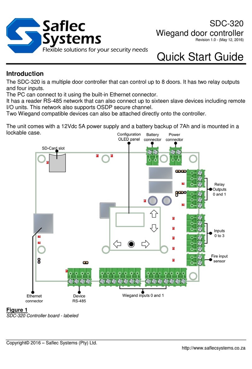
The SDC-650 is a multiple door controller that can control up to 8 doors. It has five relay outputs
and eight inputs.
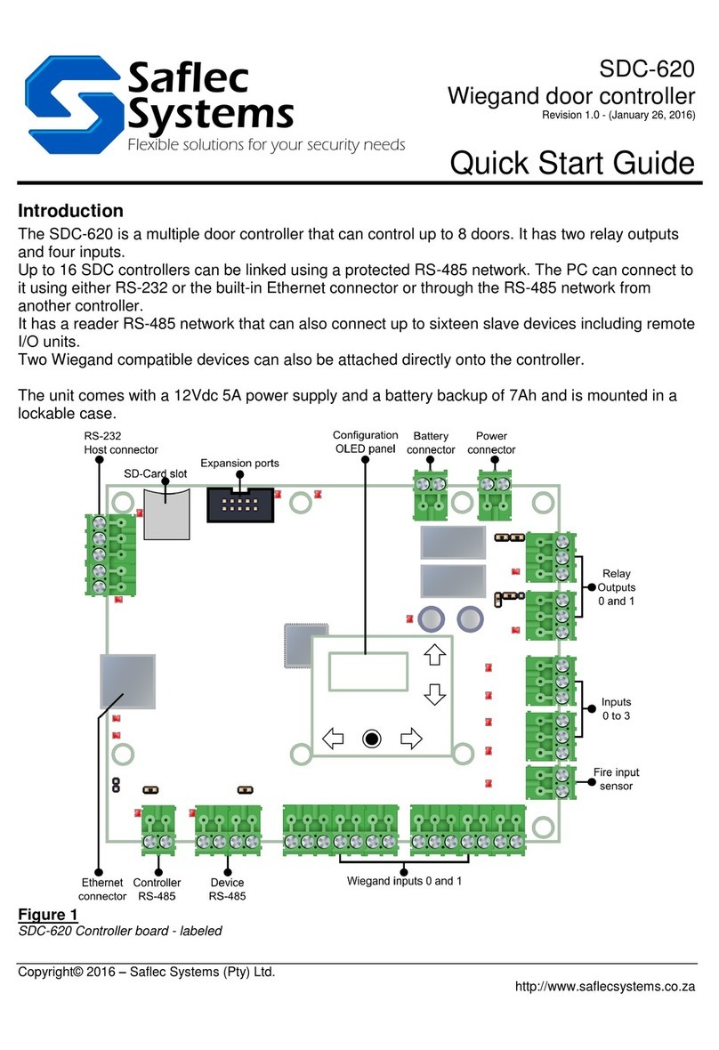
Up to 16 SDC controllers can be linked using a protected RS-485 network. The PC can connect to
it using either RS-232 or the built-in Ethernet connector or through the RS-485 network from
another controller.
It has a reader RS-485 network that can also connect up to sixteen slave devices including remote
I/O units.
The unit comes with a 12Vdc 5A power supply and a battery backup of 7Ah and is mounted in a
lockable case.
Figure 1
SDC-650 Controller board - labeled

SDC-650 Multiple door controller
2
Introduction
Copyright© 2015 –Saflec Systems (Pty) Ltd. http://www.saflecsystems.co.za
Figure 2
Possible position for an SDC-650 in a SACS access control system.

SDC-650 Multiple door controller
3
Copyright© 2015 –Saflec Systems (Pty) Ltd. http://www.saflecsystems.co.za
The configuration and diagnostics OLED panel
The configuration panel has been added to simplify some configuration tasks for the installer. It
has an OLED screen and 5 buttons for control. The Left and Right buttons are used to change
pages or move to another field within a configuration page when configuring. The Up and Down
buttons are used on all number fields to increase or decrease the value and the Enter button is
used to apply changes or to activate a command.
Once the controller is given power the panel will be active. If the screen is blank, it will be in
screen-saving mode. Tapping any button will awaken the screen and allow you to configure the
device.
Figure 3
The configuration and diagnostics OLED panel.
Various tasks can be performed from the menu system, however only a few tasks will be covered
in this guide.
NOTE: Some functions are password protected and the password must be entered before being
given access to that function. The default password is ‘1234’ – but this can be changed from the
web interface. When the password is requested you would use the Up and Down buttons to
change the letter or number shown until it is correct, then Right to move to the next character. This
process would repeat until the entire password has been entered, then the Enter button is pressed
to confirm.

SDC-650 Multiple door controller
4
Copyright© 2015 –Saflec Systems (Pty) Ltd. http://www.saflecsystems.co.za
Step 1: Connecting the power supply
Figure 4
Connections to power supply and battery
The controller comes with a 12Vdc power supply which gets connected to the top of the board.
The controller also has a battery voltage monitor should you wish to monitor the status of the
battery.
When the power is connected the power indication LED in the middle of the board will turn on.
NOTE: Please ensure that the power is switched off whenever wiring things like digital outputs in
order to protect the board from accidental shorts or power spikes.
Step 2: Set the address using the configuration menu
The SDC-650 communicates with other controllers via a multi-drop RS-485 communications
network. Each controller on this network requires a unique address for communications and
identification. Duplicate addresses will cause communication problems.
The address of the controller can be a number from 0 to 15. This setting can be adjusted using the
menu on the configuration panel.
Press the Right button until a page headed ‘Node address’ is visible.
Press the Enter button to edit the value.
If the password is required the password page will be shown –enter the password as
explained in the section above entitled ‘The configuration and diagnostics OLED panel’.
Press the Up and Down buttons to select the correct node address.
Press Enter to save the changes temporarily to memory.
In order to save this change for reboot, browse through the pages until you get to a page
entitled ‘Save Settings’. Press Enter to execute the save action then reboot the controller
for the change to take effect.
Note: This address will be the same address as used in the SACS software.

SDC-650 Multiple door controller
5
Step 3: Connecting the RS-485 reader network
Copyright© 2015 –Saflec Systems (Pty) Ltd. http://www.saflecsystems.co.za
Step 3: Connect the RS-485 controller network
All controllers in a specific network will be connected together via an isolated multi-drop RS-485
network. This network will be connected as detailed in the figure below.
Figure 5
Wiring configuration for multiple controllers on the RS-485 controller network
NOTE: The RS-485 network requires termination on the first and last controller on the line by
shorting J6. Controllers in the middle of the line must not have the termination jumper inserted as
this can cause network problems.
In the diagram above you will see that the controller on the left is terminated while the controller
on the right isn’t. This is because the cables go off to another controller; hence the controller is in
the middle of the line and must not be terminated.
Step 4: Connecting the RS-485 device network
All readers or IO expansion boards are connected to each other via an RS-485 multi-drop network
which is connected to the controller as detailed in the figure below.
Figure 6
Wiring configuration for an SSR reader on the RS-485 device network

SDC-650 Multiple door controller
6
Copyright© 2015 –Saflec Systems (Pty) Ltd. http://www.saflecsystems.co.za
NOTE: The power supplied by the controller is dependant on the length of the cable and the
number of readers being supplied with power. Should the cable length be too long, or should there
be too many readers the voltage drop might cause the power to be insufficient.
The devices do not have to be powered from the controller. They can also be powered individually
from a separate power supply, should this be preferable, however best practice would be to strap
the ground of the external power supply to the ground on the controller as per the previous
diagram to prevent issues with a ground potential difference.
Step 5a: (Optional) Connect the Ethernet Host interface
One of the controllers on the RS-485 controller network has to be connected to the PC for the
device network to be able to communicate with the host system. This can be done through either
the Ethernet connection or the RS-232 connection.
The Ethernet cable is a non-‘power over Ethernet’ cable to an RJ-45 plug. The typical wiring used
for the Cat5 cable that is used for this connector is the ‘T-586B’ wiring scheme as seen in the
figure below.
Figure 7
Wiring used in the RJ-45 plug as seen from below.
Configure the network configuration for the controller using the diagnostics panel:
Browse the menu to the page entitled ‘IP Address’
Press ‘Enter’ to edit the address
Using the Right and Left buttons select the part of the address that you’d like to change.
The part will be highlighted as in the figure below.
Use the Up and Down buttons to increase or decrease the number at that position. Holding
the button down will speed up the change.
Figure 8
The pages as seen during configuration.
Repeat the above process for the ‘Subnet Mask’and ‘Gateway’ settings.
Once you’ve set everything correctly, browse through the pages until you get to a page
entitled ‘Save Settings’. Press Enter to apply the change then reboot the controller.

SDC-650 Multiple door controller
7
Step 7: Connecting the digital outputs
Copyright© 2015 –Saflec Systems (Pty) Ltd. http://www.saflecsystems.co.za
Step 5b: (Optional) Connect the RS-232 Host interface
As discussed in 5a this step is necessary if the controller is to be linked to the Host using the RS-
232. This step is unnecessary if the controller uses the RS-485 to another controller that is linked
to the host or if the Ethernet interface is being used.
Figure 9
RS-232 wiring configuration for the PC host interface
Step 6: Connecting the digital inputs
Before wiring the digital inputs make sure that the power is switched off on the controller board.
When looking at the controller board with the power connector on the top right of the board, the
inputs are arranged in ascending order from left to right with a shared common between each
input pair. See the diagram below on how to correctly wire them.
Figure 10
Example wiring of inputs 0 and 1 to a pushbutton and closed sensor
Step 7: Connecting the digital outputs
Before wiring the digital inputs make sure that the power is switched off on the controller board.
When looking at the controller board with the power connector to the right, the outputs are
arranged in ascending order from left to right.
The outputs can provide 12Vdc power, or simply act as a potential free contact, allowing external
DC or AC power to be switched through the relay.
The configuration of this output mode can be accomplished using the jumpers J11 to J15.
Possible output modes are listed below.

SDC-650 Multiple door controller
8
Copyright© 2015 –Saflec Systems (Pty) Ltd. http://www.saflecsystems.co.za
Output mode 1: Externally powered outputs (Default)
To set the output to externally powered mode, place a single jumper in the center of the jumper
pin strip as displayed in the diagram below.
Figure 11
Jumper setting for J11 to J15 –externally powered outputs –relay switched
When in this mode, only the relay is switched when the output is activated. This allows for devices
like AC switched locks to be supplied or external power to be provided for an output. Care must be
taken not to exceed the contact ratings listed in the section entitled ‘Contact ratings for the output
relays’.
Figure 12
Example wiring for an externally powered magnetic lock –Normally closed
Output mode 2: Internally powered outputs
To set the output to internally powered mode, place two jumpers on the left and right side of the
jumper pin strip as displayed in the diagram below.
Figure 13
Jumper setting for J11 to J15 –internally powered outputs
When in this mode, 12Vdc power will be switched through the board from the power supply
connected to the board. It will have battery backup (If the standard power supply is used) so that
minor power interruptions will not disrupt the output power.
Make sure that sufficient power is available from the power supply for all internally switched
outputs, for the controller and for any readers powered from the power supply.
Figure 14
Example wiring for an internally powered magnetic lock –normally closed.

SDC-650 Multiple door controller
9
Copyright© 2015 –Saflec Systems (Pty) Ltd. http://www.saflecsystems.co.za
Important: When driving inductive loads such as strike locks, care should be taken to prevent a
back-EMF voltage spike. In order to do this a freewheeling diode (also known as flyback diode)
should be connected across the load as seen in the figure below.
Figure 15
Diagram showing freewheeling diode over an internally powered inductive load (eg. strike lock) –normally open.

SDC-650 Multiple door controller
10
Step 7: Connecting the digital outputs
Copyright© 2015 –Saflec Systems (Pty) Ltd. http://www.saflecsystems.co.za
The Web interface
The Web interface can be located by pointing the PC browser to the IP address configured on the
SDC-650 device.
Figure 16
The Web interface front page
It shows basic diagnostics information on the main page, but the links at the bottom will require a
username and password for authentication. The default username is ‘root’and password is
‘Netsilicon’. These passwords can be changed from the ‘Change Password’link at the bottom.
Figure 16
The Change Password page before and during password change
When the password is entered and verified a save button will appear to persist the change.

SDC-650 Multiple door controller
11
Product specifications
Copyright© 2015 –Saflec Systems (Pty) Ltd. http://www.saflecsystems.co.za
PRODUCT SPECIFICATIONS
Power requirements
Operating Voltage (DC)
10 to 14 Vdc
Maximum Current
300 mA
Maximum Current (Including two
SSR-201 proximity card readers)
500 mA
Environmental characteristics
Operating Temperature
0°C to +70°C
Storage Temperature
-10°C to +80°C
Enclosure Rating
IP54
Inputs
Input Type
Digital
Typical Input Voltage (Internal Mode)
0 to +12Vdc
Maximum Input Voltage
-12 to 36Vdc
Maximum Input Current
7.3 mA
Outputs
Output type
Relay –internally powered or potential free contact
Maximum voltage (AC)
250Vac
Maximum voltage (DC)
220Vdc
Internally powered Outputs
Maximum combined current
3.7A
Recommended maximums per relay
750mA at 12Vdc
Externally powered Outputs
Recommended current (DC)
2A at 30Vdc
Recommended current (AC)
1A at 125Vac
Note: Care must be taken not to exceed the contact ratings listed to prevent damage to the controller.
RS-485 controller network
Transient Protection
Yes
Protection type
Galvanic isolation
Maximum protection voltage
2kV
Maximum Network Length
1000 metres
RS-485 reader network
Transient Protection
Yes
Protection type
Galvanic isolation
Maximum protection voltage
2kV
Maximum Network Length
500 metres (Data only)
RS-232 Host Interface
Transient Protection
No
Maximum Cable Length
15 metres
Auxiliary power output
Voltage (DC)
12Vdc
Total output current
3A

SDC-650 Multiple door controller
12
Copyright© 2015 –Saflec Systems (Pty) Ltd. http://www.saflecsystems.co.za
Notes:
Table of contents
Other Saflec Systems Controllers manuals