Sahara Sahara-Pak HC-1260 User manual

Sahara-Pak
Model HC
Heat-of-Compression
Regenerative
Air Dryer
Prior to installation and
start-up of this dryer,
please read and
implement Section 1 o
f
this manual,
Installation & Start-up.
Prior to operating this
dryer, it is advised that
this entire manual be
studied and clearly
understood.
This dryer is designed
to be used only with a
non-lubricated
compressor. Use with
a lubricated
compressor will void
all warranties and may
cause severe damage.
SAHARA AIR PRODUCTS
A Div. of HENDERSON ENGINEERING COMPANY, INC.
95 North Main Street Sandwich IL 60548
815-786-9471 800-544-4379 Fax: 815-786-6117
www.saharahenderson.com
Instruction
Manual
Please have the following
information available, should
the need arise to contact
Henderson Engineering with
any questions regarding this
air dryer:
Model No. HC-1260
Serial No. 63116

INSTRUCTION MANUAL
Model HC
Reference 219 Rev 2
Page 2 of 46 06/20/2013
This instruction manual from Henderson Engineering Co., Inc. is an aid in getting to know the dryer
better and in utilizing its possibilities for application in accordance with its intended use. Furthermore,
this manual contains important information for safe, proper, and economic operation.
Please follow these important steps to get the most from your air dryer:
1Know these Symbols
Warning against electrical voltage!
This symbol indicates that dangerous voltage constituting a risk of electric shock is present.
Attention / Danger!
This symbol indicates that there are important operating and maintenance instructions
which you should read closely to avoid danger and prevent problems.
Advice
This symbol indicates a procedure of particular interest or importance. All advice must be
followed to ensure proper use of this adsorption dryer.
2Read this Instruction Manual carefully
The information in this manual can help you take full advantage of the air dryer’s many
features, and ensure years of safe, reliable operation. Read the entire manual for a clear
understanding of the air dryer’s operation. This manual must always be kept within reach at
the site of the dryer installation.
The operator is to make sure that all maintenance, inspection, and assembly work is
carried out by personnel who are authorized and qualified, who are adequately informed,
and who completely understand the contents of this instruction manual. Should the
personnel not possess the necessary knowledge, they must be trained and instructed. If
need be, this training may be carried out by the manufacturer at the request of the operator.

INSTRUCTION MANUAL
Model HC
Reference 219 Rev 2
Page 3 of 46 06/20/2013
TABLE OF CONTENTS
SECTION 1: INSTALLATION & START-UP
1.0 Installation
1.0.1 Dryer Location and Mounting Specifications
1.0.2 Preventative Maintenance Prior to Start-up
1.0.3 Afterfilter
1.0.4 Air Supply
1.0.5 Air Discharge Piping
1.0.6 Drain Piping
1.0.7 Cooling Water
1.1 Start-up
1.1.1 Safety Precautions
1.1.2 Pressurizing Dryer
1.1.3 Operator Interface
SECTION 2: OPERATION & MAINTENANCE
2.0 Operation
2.0.1 General Information
2.0.2 Description
2.0.3 Theory of Operation
2.0.4 Pressure Vessel Regulations
2.0.5 Airtightness Test

INSTRUCTION MANUAL
Model HC
Reference 219 Rev 2
Page 4 of 46 06/20/2013
TABLE OF CONTENTS (continued)
2.1 Maintenance
2.1.1 Suggested Preventive Maintenance Schedule
2.1.2 Adjustments
2.1.3 Desiccant
2.1.4 Afterfilter
2.1.5 Filter Accessories
SECTION 3: TROUBLESHOOTING & CUSTOMER SERVICE
3.0 Troubleshooting
3.0.1 Short-Term Shut-Down
3.0.2 Shut-Down in Case of a Fault or for Maintenance
3.1 Customer Service
SECTION 4: WARRANTY
4.0 Warranty
SECTION 5: SPECIFICATIONS, PARTS LIST, & DATA REPORTS
SECTION 6: AUXILIARY MANUALS (IF APPLICABLE)
SECTION 7: CUT SHEETS
SECTION 8: DRAWINGS

INSTRUCTION MANUAL
Model HC
Reference 219 Rev 2
Page 5 of 46 06/20/2013
SECTION 1
INSTALLATION & START-UP
Prior to installation and start-up of this dryer,
please read and implement this section.

INSTRUCTION MANUAL
Model HC
Reference 219 Rev 2
Page 6 of 46 06/20/2013
SECTION 1: INSTALLATION & START-UP
1.0 Installation
Connect the compressor interlock relay to compressor load condition, if
dryer load is less than 50%. Refer to the electrical drawing in Section 8.
This dryer is designed to be used only with a non-lubricated compressor.
Use with a lubricated compressor will void all warranties and may cause
severe damage.
Upon delivery of the dryer, it must be checked for damage that may have
occurred during transport. If there is any evidence of damage due to
shipping, immediately enter a claim with the carrier. Shipping damage is
not covered by warranty.
Use the appropriate, load-rated lifting equipment and observe safe lifting
procedures during all operations of installation. The equipment should be
unloaded as close as possible to the installation site to minimize any
chances of equipment damage.
If the dryer is to be stored for a prolonged period of time, it should be
stored in a dry place, preferably indoors, protected from the elements
including freezing or extremely warm temperatures. Keep all openings
closed until connections are made.
1.0.1 Dryer Location and Mounting Specifications
1.0.1.1 The Sahara-Pak HC dryer is designed for indoor operation with
ambient temperatures between 35F - 100F. The standard
electrical components are designed specifically for NEMA 4
(refer to the Specifications in Section 5). Should it be desirable
to locate the dryer outdoors, it would be necessary to protect
the dryer from rain by placing a roof over the dryer and to
protect cooling water and separator drain lines from freeze-up
by heat tape or other suitable means.
1.0.1.2 Locate the dryer as close to the air compressor as possible to
conserve "Heat-of-Compression" energy. Also, since the piping
from compressor to dryer requires insulation, a short run of
piping will simplify installation. Be sure that the intended
location allows for adequate clearance around the dryer to
facilitate servicing.

INSTRUCTION MANUAL
Model HC
Reference 219 Rev 2
Page 7 of 46 06/20/2013
1.0.1 Dryer Location and Mounting Specifications (continued)
1.0.1.3 Locate the dryer in the coolest possible location, providing
adequate space around the dryer for servicing all components.
An overhead clearance of not less than three feet above each
tower is required for loading of the desiccant. Access
clearance of three feet in front of the control panel should be
provided. For mounting dimensions, refer to the general
assembly drawing in Section 8.
1.0.1.4 Remove all protective shipping crates, flange covers, etc.
1.0.1.5 Utilizing the mounting holes provided on the skid, anchor the
HC dryer to a solid, level foundation designed to support the
dryer. Should vibrations occur on the installation location, the
dryer is to be placed onto vibration dampeners.
1.0.1.6 Because of vibration during shipping and installation, some
lines, fittings, bolts, and connections may have loosened;
therefore, inspect all and tighten if required.
1.0.1.7 Locate and install any items that may have shipped loose from
the dryer, such as exhaust mufflers or auxiliary filters.
1.0.1.8 If desiccant has been shipped separate and must be installed,
reference Section 2 for desiccant installation instructions and
Section 7 for the Material Safety Data Sheet (MSDS). Wear
protective goggles and mask when working with desiccant.
1.0.1.9 Connect the dryer to a correctly sized power supply. The
standard HC dryer requires a 115V, 60 cycle connection. For
voltage and current requirements, refer to the Specifications in
Section 5.
1.0.1.10 Ground the frame of the dryer in accordance with the end
user’s local electrical codes.
1.0.1.11 Disconnect switch is not provided with the dryer and must be
supplied by the end user with proper overload protection
according to local electrical codes.

INSTRUCTION MANUAL
Model HC
Reference 219 Rev 2
Page 8 of 46 06/20/2013
1.0.1 Dryer Location and Mounting Specifications (continued)
1.0.1.12 For electrical connections, refer to the electrical drawing in
Section 8. Be sure to look for any auxiliary connections, such
as remote alarm contacts, compressor interlock relay (if
needed), or analog (4-20mA) signals.
1.0.1.13 Ensure that the inlet and outlet connections to and from the
dryer are made using the correct rated fittings and piping to
meet the design conditions. For connection details, refer to the
flow schematic in Section 8.
1.0.1.14 Insulate the pipe between the compressor and dryer to
minimize heat loss.
1.0.1.15 Do not hydrostatically test the pressure vessels. All HC dryer
pressure vessels are hydrostatically tested at 1.3x the design
pressure, per ASME code, after fabrication and before
assembly of the dryer.
1.0.1.16 It is recommended that the common alarm relay, located in the
dryer control panel, be connected to the control room or
operator station, so that an immediate response to the dryer
alarm may be given when required.
1.0.1.17 If the equipment is installed in a high traffic area, protective
barriers may be required to prevent possible damage of
equipment and to prevent contact with hot surfaces.
1.0.2 Preventative Maintenance Prior to Start-up
1.0.2.1 All air dryers are tested at the factory for leak-tight joints and
tightness of bolts; however, during shipment, some bolts may
vibrate loose. We have no control over the handling our
compressed air systems receive after leaving our factory. To
prevent costly problems at start-up and operation, all bolts
should be checked for tightness prior to system pressurization.
This will assure gasket life as well as prevent possible gasket
blowout. Gasket joints should be bubble tested after four or
five complete cycles of the dryer, to ensure gaskets are
sealed. Any loose joints will need to be re-tightened and re-
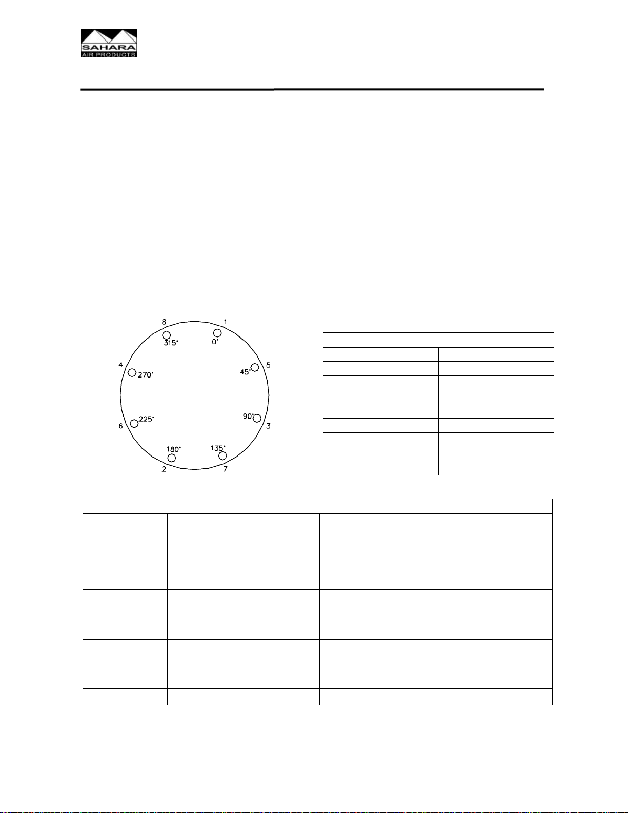
tested for leaks. Following is a comprehensive procedure for
tightening all pressurized gasketed joints. If the dryer includes
manual butterfly valves, valves must be totally closed before
re-torquing bolts.

INSTRUCTION MANUAL
Model HC
Reference 219 Rev 2
Page 9 of 46 06/20/2013
1.0.2 Preventative Maintenance Prior to Start-up (continued)
1.0.2.2 TIGHTEN BOLTS IN SEQUENTIAL ORDER (i.e. 0- 180,
90- 270, 45- 225, and 135- 315) until final torque is
reached.
1.0.2.3 Use ROTATIONAL TIGHTENING until all bolts are stable at
final torque level. (Two complete times around is usually
required.)
NOTE: We regret any inconvenience this may cause; however, we feel this
preventative procedure will save time and money in the long run.
Failure to follow this procedure may result in premature gasket
failure which is not covered by warranty.
FLANGE BOLT TIGHTENING TORQUES
150# FLANGE RATING
SIZE BOLT
QTY. BOLT
SIZE
RECOMMENDED
TORQUE / BOLT
(FT. LBS.)
MINIMUM TORQUE
(FT. LBS.) MAXIMUM TORQUE
(FT. LBS.)
1" 4 ½" 16 14 64
1 ½" 4 ½" 32 28 64
2" 4 5/8" 64 56 128
3" 4 5/8" 110 96 128
4" 8 5/8" 78 68 128
6" 8 ¾" 148 129 230
8" 8 ¾" 201 175 230
10" 12 7/8" 191 166 372
12" 12 7/8" 254 221 372
Based on 1/16" gasket material.
If other than 150# flange rating, consult Henderson Engineering.
FLANGE BOLT
TORQUE PROCEDURE
8 BOLTS
SEQUENTIAL ORDER ROTATIONAL ORDER
1-2 1
3-4 5
5-6 3
7-8 7
2
6
4
8

INSTRUCTION MANUAL
Model HC
Reference 219 Rev 2
Page 10 of 46 06/20/2013
1.0.3 Afterfilter
1.0.3.1 Use of a prefilter is not necessary, or recommended, with a
heat-of-compression Model HC dryer. It is extremely important,
however, that a afterfilter be provided in the dryer installation.
The afterfilter eliminates the possibility of desiccant dust
carryover into the instrument air system.
1.0.3.2 If the dryer is shipped with the afterfilter loose or with the
afterfilter skid-mounted on a separate steel frame, below are
the installation instructions for these models.
1.0.3.2.1 Afterfilter Installation
Mount afterfilter in such a way as to allow
clearance for the element installation and
removal.
The filter must be piped, so that the correct flow
direction indicated on the filter is followed.
Ensure that all piping and valves are equivalent
or larger in size to the dryer inlet connection.
1.0.3.2.2 Afterfilter Skid-Mounted with 3-Valve Bypass
Installation
Filter skid should be located as close to dryer as
possible. Use the skid bolt holes to secure the
assembly.
Ensure that the skid is located such that the 3-
valve bypass will bypass the filter when in use.
Check the flow direction of each filter to ensure
the afterfilter is connected to the outlet pipe of
the dryer.
Connect the filter skid piping and dryer skid
piping using materials and fabrication procedures
that are suitable for compressed air pressure
piping.

INSTRUCTION MANUAL
Model HC
Reference 219 Rev 2
Page 11 of 46 06/20/2013
1.0.4 Air Supply
1.0.4.1 The air supply should be between 250F - 400F, and 100
PSIG - 125 PSIG compressed air.
1.0.4.2 In piping the air to the dryer, use a pipe size equal to or larger
than the dryer line size, keep the length of piping as short as
possible, and insulate the piping.
1.0.4.3 The compressed air generated by a reciprocating compressor
contains some pulsation; the amplitude and frequency being
related to the number of stages, speed, etc. Normally, the
pulsation associated with a multi-stage compressor will not
affect the operation of the dryer; however, it is recommended
that a PULSATION DAMPENER be installed between a
reciprocating compressor and the dryer to prevent excessive
desiccant breakup and component fatigue. A pulsation
dampener should be used in any installation where the
pulsation seems excessive. As with the air supply piping, the
pulsation dampener, if installed, should be insulated.
1.0.4.4 If the compressed air system cannot be shut down during
dryer maintenance periods, a six-valve block and bypass
valving arrangement should be installed to allow for isolating
and depressurizing the dryer, while still maintaining
compressed air delivery. Note that the bypassed air will not be
dried. The cooler and separator should still be utilized. The
scheduled maintenance periods occur at intervals of 2000
hours running time and normally require only a couple of hours
to complete.
1.0.5 Air Discharge Piping
1.0.5.1 If an air receiver is required in the compressed air system for
air storage, it should be installed downstream of the dryer.
Here it will store dry air (and require no draining). This will
eliminate the possibility of overloading the dryer with stored air
in wet receivers.

INSTRUCTION MANUAL
Model HC
Reference 219 Rev 2
Page 12 of 46 06/20/2013
1.0.6 Drain Piping
1.0.6.1 All the moisture removed from the compressed air is drained
away through the drain valves under the separator. Both
valves should be connected to a suitable drain through drain
piping of sufficient size for its length, to avoid pressure drop or
blockage due to contaminants on the drain water. It is
recommended that at some convenient point in the drain
piping, the water flow should be visible, so that proper drain
operation can be visually verified.
1.0.7 Cooling Water
1.0.7.1 An adequate supply of clean water must be available to the
dryer INTERCOOLER. The use of dirty or scale forming water
should be avoided. DIRTY water reduces cooling efficiency
and will require regular "back flushing" to maintain
performance.
1.0.7.2 The standard Sahara-Pak HC dryer is designed to use
approximately 3.77 GPM per 100 SCFM of 85F cooling water.
The air exiting the intercooler should be 95F or less as
indicated by the temperature screen on the panel view. This
temperature is located under the heading of cooler outlet
temperature. The cooling water inlet and outlet pipe size is
listed in the specifications at the front of this manual. The inlet
and outlet are clearly marked, but in case the unit has been
repainted or the markings are otherwise unreadable, the
cooling water flow is COUNTER-CURRENT to the air flow.
That is, the cooling water inlet is at the SEPARATOR end of
the cooler.
1.0.7.3 The performance of the Sahara-Pak HC dryer is directly
related to the cooling water temperature; thus, the cooling
water should be as cold as possible. High cooling
temperatures will adversely affect the outlet dew point.
1.0.7.4 The cooling water pressure drop is approximately 2 PSID
through the cooler at the above stated water flow rate, so the
cooling water supply pressure and supply and return piping
should be sized accordingly.
1.0.7.5 Do not install a thermostatically controlled water regulating
valve on the dryer and operate the cooling water in series, as
this would seriously reduce the cooling water supply to the
compressor.

INSTRUCTION MANUAL
Model HC
Reference 219 Rev 2
Page 13 of 46 06/20/2013
1.1 Start-up
Prior to start-up:
It is recommended that the operational program of the dryer and the
wiring schematic be studied before operating the dryer.
Desiccant level must be checked. Wear protective goggles and mask
when working with desiccant. Reference Section 2 for desiccant
instructions and Section 7 for the MSDS.
All pipes and wire connections must be tightened.
Pipes must be checked for presence of scale, abraded material from the
threading, or other similar impurities.
All shut-off valves on the dryer, afterfilter, and on the bypass line should
be closed.
The ambient temperature must not be less than 33F.
1.1.1 Safety Precautions
As with any piece of industrial machinery, common sense safety
precautions should be observed.
1.1.1.1 Portions of the dryer and related piping will reach temperatures
which could cause serious burns, if not insulated or shielded.
Personnel working on or near the dryer should be cautioned to
this particular danger.
1.1.1.2 Pull the main disconnect switch before attempting to work or
perform maintenance on the dryer.
1.1.1.3 Do not attempt to remove any dryer parts while the dryer is
pressurized. First, isolate the dryer (if bypass valving has been
installed) or shut off the compressor. Then, slowly
depressurize the dryer through the afterfilter bleed or the
automatic drain bleed (under separator).
1.1.1.4 Do not allow tools or other obstructions to interfere with the
shaft of the switching valves. Keep all body parts away from
the switching valve shafts while the dryer is operating; the
actuation is sudden and could cause bodily injury.

INSTRUCTION MANUAL
Model HC
Reference 219 Rev 2
Page 14 of 46 06/20/2013
1.1.2 Pressurizing Dryer
1.1.2.1 Prior to pressurizing the dryer, verify the following:
Dryer ON/OFF switch is in the OFF position.
System outlet block valve is closed.
Cooling water is turned on to the aftercooler.
1.1.2.2 Slightly open the inlet isolation valve, slowly flowing
compressed air to the system. Opening this valve too quickly
may cause damage to the dryer including the desiccant, tower
screens, and filter elements.
1.1.2.3 When full system operating pressure has been reached, all
connections should be soap bubble tested for leaks. Any leaks
should be repaired and retested, prior to placing the equipment
in service. If some gas other than the process air will be used
for leak testing, consult Henderson Engineering Co., Inc., for
its compatibility with system components before proceeding.
Fully open the inlet isolation valve.
1.1.2.4 When the system is filled with process air, is leak tight, and
start-up is completed, then slowly open the system outlet valve
to pressurize the downstream piping. During the procedure,
ensure that the dryer system pressure does not fall below 95%
of its reading prior to opening the system outlet valve. This will
protect the equipment internal components (i.e. filter elements,
desiccant) from gas velocities above design conditions.
1.1.2.5 When pressurizing is complete, fully open the system outlet
valve to place the equipment in service. Refer to Section 6 for
operator interface instructions.
1.1.2.6 Verify the system inlet pressure and temperature are at the
design operating levels.
1.1.2.7 Please note that excessive flows or rapid change in
pressure may cause damage to the air dryer skid. Every
time there is no line pressure, the dryer must be valved
out and brought up to line pressure slowly.
1.1.2.8 The dryer should be carefully monitored during the first few
hours of operation to check for malfunction.

INSTRUCTION MANUAL
Model HC
Reference 219 Rev 2
Page 15 of 46 06/20/2013
1.1.2 Pressurizing Dryer (continued)
Protect the dryer from overloads. The dryer can become
overloaded, if:
inlet flow is too high
temperature of the air at the discharge of the aftercooler is too
high
minimum operating pressure is too low
temperature of the air at the discharge of the compressor is too
low
check Specifications in Section 5 for proper operating
conditions
1.1.3 Operator Interface
NOTE: Reference Section 6 (Auxiliary Manuals) for the operational
instructions specific to the operator interface purchased.
Also in Section 6 can be found the operational instructions for
the optional dew point demand system, if installed on this dryer.

INSTRUCTION MANUAL
Model HC
Reference 219 Rev 2
Page 16 of 46 06/20/2013
SECTION 2
OPERATION & MAINTENANCE
Prior to operating this dryer,
it is advised that this entire manual be
studied and clearly understood.

INSTRUCTION MANUAL
Model HC
Reference 219 Rev 2
Page 17 of 46 06/20/2013
SECTION 2: OPERATION & MAINTENANCE
2.0 Operation
Never make any changes to the dryer that are not specifically authorized
by Henderson Engineering Co., Inc.
Only use original spare and accessory parts.
Carry out maintenance work only when the dryer is switched off,
depressurized (even though gauges may read 0, there may still be air in
the dryer), and disconnected from the electric power supply.
Multiple power sources may exist in the electrical panel. All possible
power sources must be disconnected before servicing dryer.
2.0.1 General Information
The HC dryer is used for the purpose of drying compressed air and other
gases according to its respective design. As a "standard model" the dryer
is equipped with two desiccant vessels and, depending on certain
conditions, provides pure, dry, and oil-free compressed air or gases.
The HC dryer is built according to the latest technological developments.
Its use can endanger personnel and can lead to considerable damage to
the dryer and other material assets if:
it is operated by personnel not trained or instructed in its use
it is improperly used
it is improperly maintained or serviced
This can result in the loss of all damage claims.
This dryer is designed for neutral media (gas) free of aggressive water,
oil, and solid elements. Henderson Engineering Co., Inc., accepts no
liability for corrosion damage and malfunctions caused by aggressive
media.
Applications other than those mentioned in this manual must be agreed
to by Henderson Engineering Co., Inc., and confirmed in writing.

INSTRUCTION MANUAL
Model HC
Reference 219 Rev 2
Page 18 of 46 06/20/2013
2.0.1 General Information (continued)
In the interest of further development, Henderson Engineering Co., Inc.,
reserves the right to make changes at any time, which, in keeping with
the essential characteristics of the dryer described here, may be
necessary for increasing efficiency or for reasons relating to safety or to
normal business practice.
2.0.2 Description
The Sahara-Pak HC dryer is a complete system consisting of the
following major components:
2.0.2.1 Drying Vessels (insulation optional)
Two ASME Code stamped vessels containing Activated
Alumina desiccant (refer to the Specifications in Section 5 for
quantity) are firmly mounted on a structural steel base. Each
vessel is provided with stainless steel desiccant retaining
screens at both inlet and outlet. Separate desiccant fill and
drain connections allow for fast and easy desiccant
replacement without disturbing process piping. A safety relief
valve is installed on each vessel.
2.0.2.2 Switching Valves
Main compressed air flow through the Sahara-Pak HC dryer is
controlled by reinforced teflon-seated high performance
butterfly valves (3" and larger). Two inch and smaller are
standard 2-way rack and pinion operated ball valves. This
improved 2-way valve design provides for lower overall system
pressure drop than multi-port valve designs. It also eliminates
undesirable heat transfer between compressed air streams
simultaneously flowing through the same valve internal plug,
rotor, or ball.
The valves are opened and closed by over-sized actuators.
These actuators are driven by well-filtered, cool, dry air
supplied by the control air filter. The coalescing quality filter
element contained therein removes all particulates above 0.3
micron in size; thereby assuring long pneumatic actuator life.
Control air lines need no lubricators, as the pneumatic
actuators have been permanently pre-lubricated.
Speed control valves are provided, to slow the closing of all
tower switching valves to prevent upstream compressor dead-
heading.

INSTRUCTION MANUAL
Model HC
Reference 219 Rev 2
Page 19 of 46 06/20/2013
2.0.2 Description (continued)
2.0.2.3 Check Valve
The standard Sahara-Pak HC dryer design employs a single
check valve (CV1) which remains open during the offstream
tower cooling step; thereby allowing cooling air to return to the
outlet air flow. This check valve automatically closes during
offstream tower depressurization, final stripping, and
repressurization.
The heating and cooling selector valves (V1 and V2) are
piloted by a dual coil four-way solenoid and two speed control
valves within the control air runs. The speed control valves
assure fast opening of either selector valve and slow closing of
either selector valve. This prevents any possibility of dead-
heading the upstream compressor.
2.0.2.4 Water-Cooled Intercooler, Separator, Dual Drain Trap
The standard cooler used in the Sahara-Pak HC dryer is
constructed of a carbon steel shell, tube sheets, baffles, and
copper tubes. Reference the Specifications in Section 5 for the
cooling water requirement.
The Sahara-Pak HC dryer may also use an existing aftercooler
by simply using our Cooler Accommodation Package. We
supply you with our coalescing separator and traps; you use
your own cooler; saving you the initial expense of the cooler.
The air exiting the dryer intercooler carries with it the entrained
moisture condensed in the cooler. A coalescing-type separator
(no moving parts, no maintenance) separates the liquid water
from the air stream where it drops to the drain section.
Coalescing-type Separator

INSTRUCTION MANUAL
Model HC
Reference 219 Rev 2
Page 20 of 46 06/20/2013
2.0.2.4 Water-Cooled Intercooler, Separator, Dual Drain Trap
(continued)
The Sahara-Pak HC dryer has a truly unique dual automatic
drain system to remove the water from the separator. As the
liquid level from the separator rises, the primary free float drain
opens, discharging the accumulated water.
There is a level switch and 2-way valve assembly attached to
the separator which makes a complete back-up drain system.
Should any part of the primary drain assembly fail to drain the
separator, the back-up system will drain the separator and
sound an intermittent audible alarm (85 dBA) with an alarm
light to alert operating personnel to the fact that the primary
drain needs attention.
The primary trap contains a mechanical/magnetic float. This
simple and inexpensive component is capable of providing
several months of trouble-free service before grit and pipe
scale cause it to malfunction. When this happens, water will
back-up triggering a liquid level switch to activate, sending an
electrical signal to a solenoid valve. The solenoid valve
actuates a large 2-way valve which, when open, drains out the
float chamber. As the float drops, the two-way valve closes.
Additionally, a primary drain failure alarm is activated every
time the second float chamber is forced to operate. The
primary trap may be isolated from the secondary and removed
for cleaning without shutting down the air system.
2.0.2.5 High Efficiency Afterfilter (optional)
After the compressed air leaves the second drying vessel, it
may contain small particles of desiccant dust. This material is
inert, harmless, and presents no health or safety problems;
however, to provide absolute top quality compressed air, a
high efficiency particle removal filter is recommended.
Table of contents