
Table of contents
Table of Contents
Important Safety Instructions....................................................................1
1 Product Description..............................................................................2
1.1
Electromagnetic Compatibility .....................................................................................2
1.2
Features......................................................................................................................3
1.3
Models ........................................................................................................................3
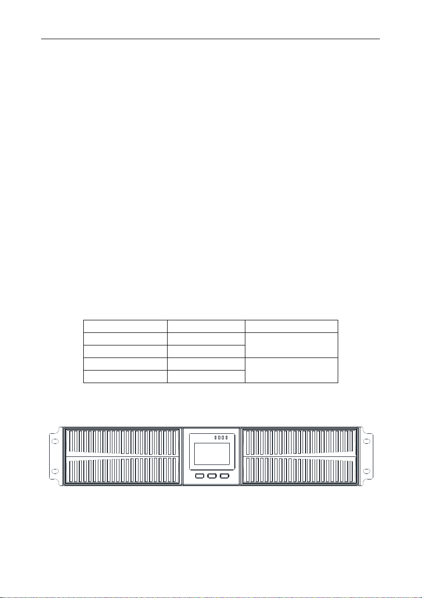
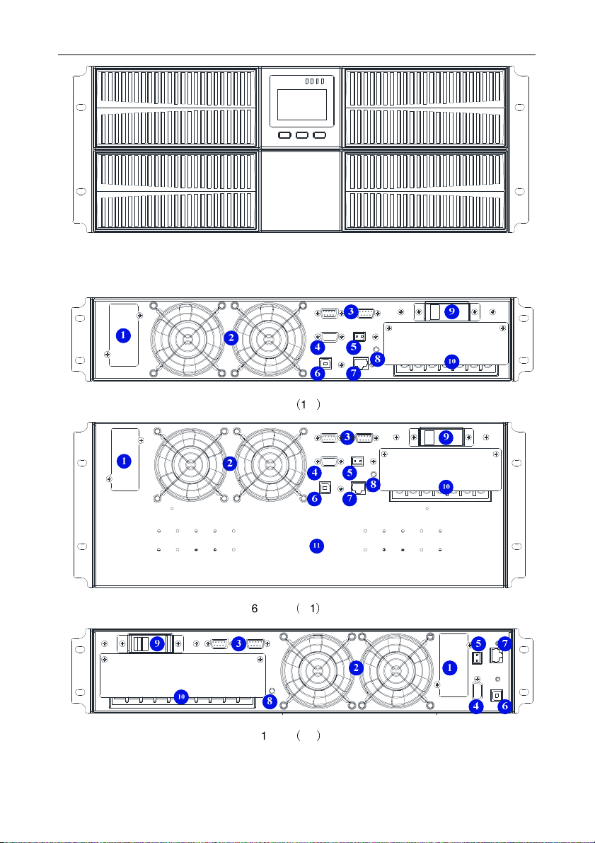
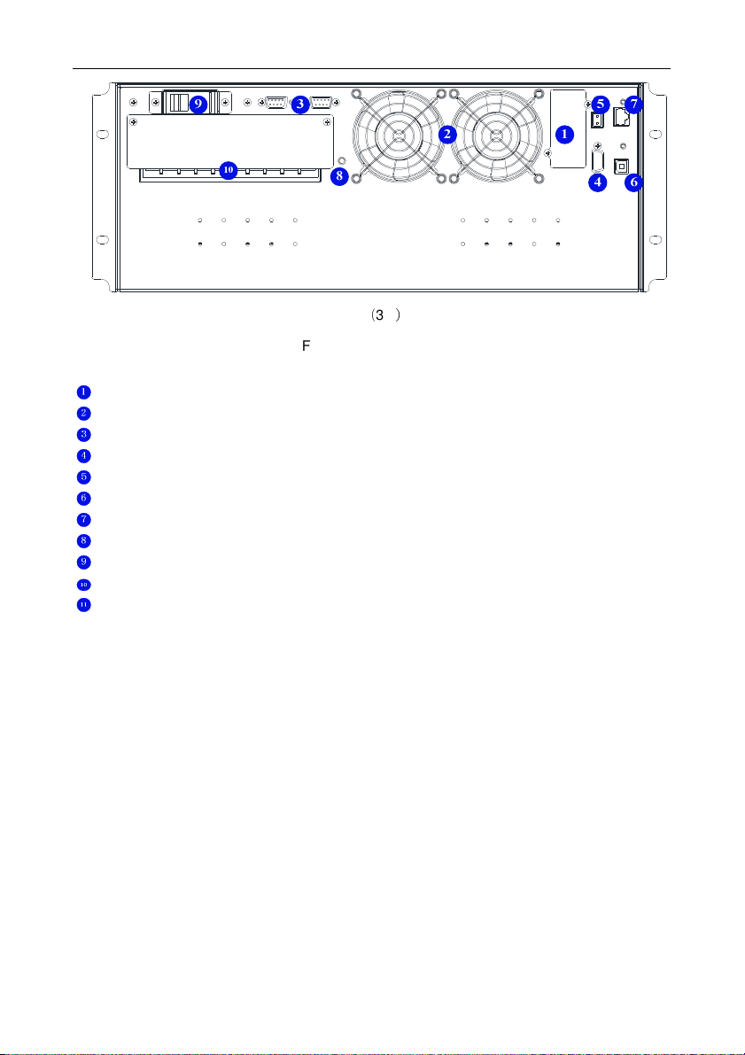
1.4
Appearance ................................................................................................................3
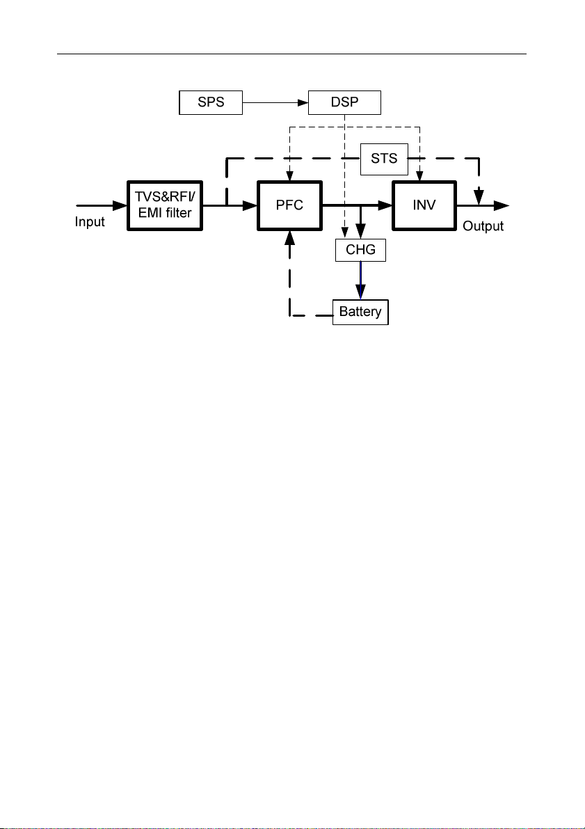
1.5
System Description .....................................................................................................6
1.6
UPS Working Mode.....................................................................................................7
1.7
Product Specifications.................................................................................................9
2 Installation ........................................................................................... 11
2.1
Unpacking and Inspection ......................................................................................... 11
2.2
Main cabinet installation............................................................................................ 11
2.3
Connect Input/Output Power .....................................................................................15
2.4
Connect External Batteries (Long Backup Model UPS) .............................................17
2.5
Connect Parallel Cables............................................................................................18
2.6
Connect Communication Cables ...............................................................................19
3 Controls and Indicators......................................................................21
4 Operation .............................................................................................27
4.1
Operation Mode ........................................................................................................27
4.2
Parallel Operation .....................................................................................................28
5 Communication ...................................................................................29
5.1
RS232 and USB Port ................................................................................................29
5.2
EPO Port...................................................................................................................29
5.3
Intelligent Cards (Optional)........................................................................................30
6 Maintenance ........................................................................................31
6.1
Battery Maintenance .................................................................................................31
6.2
Battery Disposal........................................................................................................31
6.3
Battery Replacement Procedures..............................................................................32
6.4
Precaution.................................................................................................................32
6.5
Checking UPS Status................................................................................................32
7 Troubleshooting ..................................................................................33
Annex A Parallel Setting ..........................................................................37
Annex B Battery Run Time ......................................................................37


 Plus Startup manual")


