saia-burgess PCD 7 Series User manual

Document-No. 26/793; Edition E2; 30.04.2005
Manual Modem PCD xx7 Serie

Manual Modem PCDxx7 Serie│Doc. 26/793; Ed. E2│30.04.2005
Content
1
0
Saia-Burgess Controls Ltd.
0.1 Dokument-History ........................................................................................... 3
0.2 Trademarks ..................................................................................................... 3
1 Introduction
1.1 Structure ......................................................................................................... 1-1
1.2 Restrictions ..................................................................................................... 1-2
2 Modem parameters and Main Driver functions
2.1 Configuration of the modem parameters ........................................................ 2-1
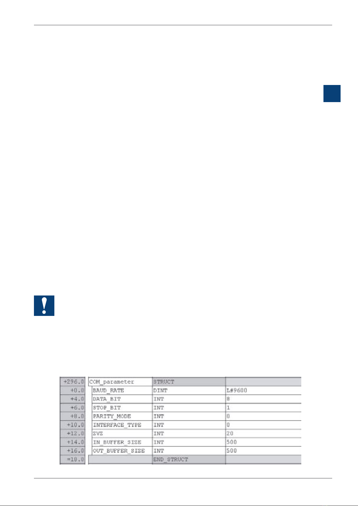
2.1.1 Structure field “COM_parameter” ................................................................. 2-1
2.1.2 Structure field “AT_COMMAND” ................................................................... 2-2
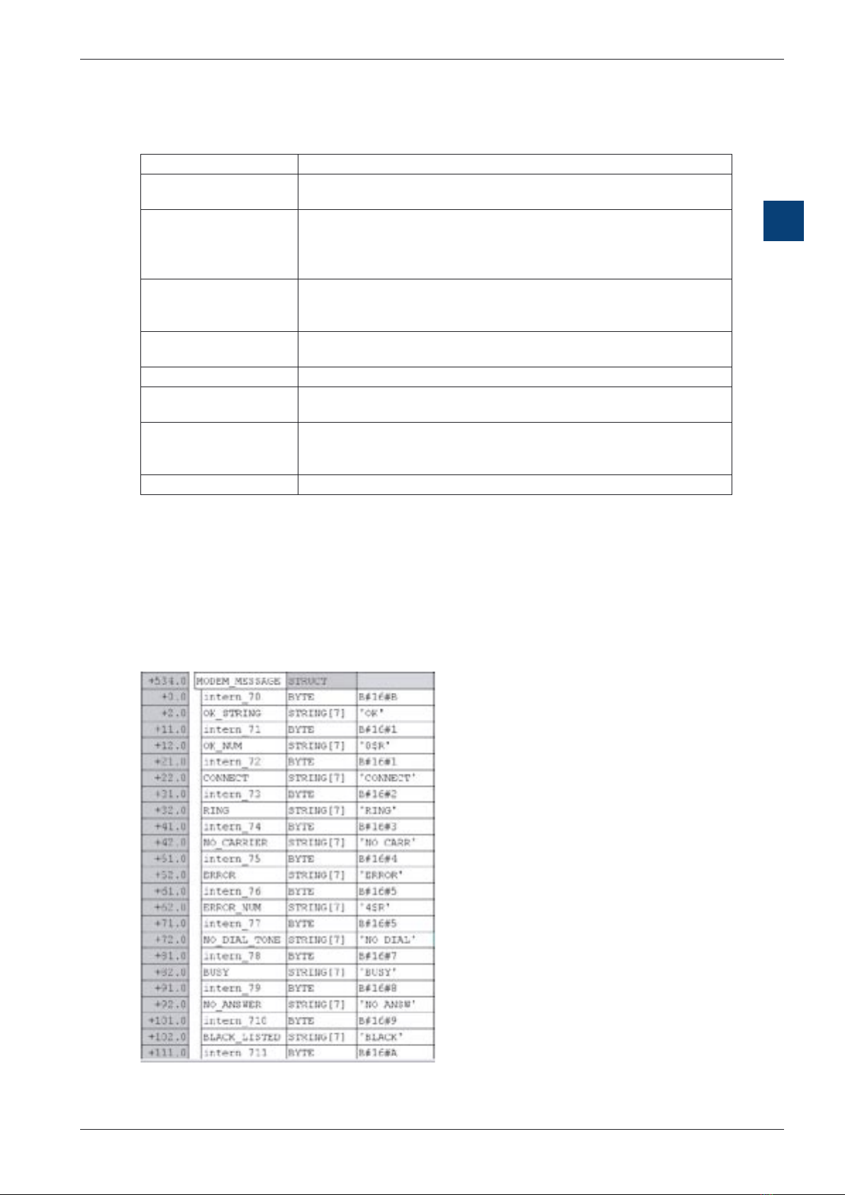
2.1.3 Structure field “MODEM_MESSAGE” ........................................................... 2-3
2.2 Main Driver function ........................................................................................ 2-5
2.2.1 Parameters ................................................................................................... 2-5
2.2.2 Function ........................................................................................................ 2-6
3 Receive and make a call
3.1 Receiving a call “Incoming call” ...................................................................... 3-1
3.1.1 Enabling the receiving ................................................................................... 3-1
3.1.2 Receiving process ......................................................................................... 3-1
3.2 Make an “Outgoing call” .................................................................................. 3-1
3.2.1 Starting call process ...................................................................................... 3-1
3.2.2 Function ........................................................................................................ 3-2
4 Protocols
4.1 Configuration DB ............................................................................................. 4-1
4.2 Enabling protocol ............................................................................................ 4-3
4.2.1 Function ........................................................................................................ 4-3
5 Example: Starting an application
5.1 Configuring the modem parameters ............................................................... 5-1
5.1.1 Parameter of the serial communication ........................................................ 5-1
5.1.2 AT command for the modem ......................................................................... 5-2
5.1.3 Answer message from the modem ............................................................... 5-2
5.1.4 Initialize DB ................................................................................................... 5-3
5.2 Initialization of the Driver ............................................................................... 5-3
5.3. Calling ............................................................................................................. 5-4
5.4 Switching the protocol ..................................................................................... 5-5
5.4.1 Configuration ................................................................................................. 5-5
5.4.2 Protocol enabling .......................................................................................... 5-6
6 Sending SMS
6.1 Structure ......................................................................................................... 6-1
6.2 Parameterization of the SMS system .............................................................. 6-1
6.2.1 Parameter in the “DB_Modem” ..................................................................... 6-1
6.2.2 SMS system parameters “DB_SMS” ............................................................ 6-2
6.3 SMS function ................................................................................................... 6-3

Manual Modem PCDxx7 Serie│Doc. 26/793; Ed. E2│30.04.2005
Content
2
0
Saia-Burgess Controls Ltd.
6.3.1 Integration to the application ......................................................................... 6-4
7 Sending Pager Messages
7.1 Structure ......................................................................................................... 7-1
7.2 Parameterization of the Pager system ............................................................ 7-1
7.2.1 Parameter in the “DB_Modem” ..................................................................... 7-2
7.2.2 Pager system parameters “Pager_DB” ......................................................... 7-2
7.2.3 Pager ........................................................................................................... 7-3
7.3 Pager function ................................................................................................. 7-3
7.3.1 Integration to the application ......................................................................... 7-4
8 Sending SMS-TAP
8.1 Structure ......................................................................................................... 8-1
8.2 Parameterization of the TAP system ............................................................... 8-1
8.2.1 Parameter in the “DB_Modem” ..................................................................... 8-2
8.2.2 TAP SMS system parameters “DB_TAP” ...................................................... 8-2
8.3 TAP function .................................................................................................... 8-3
8.3.1 Integration to the application ......................................................................... 8-4
9 Appendix
9.1 Appendix 1, Initialization strings ...................................................................... 9-1
9.2 Appendix 2, Error Codes ................................................................................. 9-2
9.2.1 Error returned by the Modem Driver function ................................................ 9-2
9.2.2 Error return by the calling function ................................................................ 9-3
9.2.3 Error return by the SMS function ................................................................. 9-3
9.2.4 Error return by the PAGER function ............................................................. 9-3
9.2.5 Error return by the TAP SMS function .......................................................... 9-4
9.3 Appendix 3, Pager character set ..................................................................... 9-4
9.4 Appendix 4, General ....................................................................................... 9-5
9.4.1 Icons ............................................................................................................. 9-5
9.4.2 Product and documentation concept ............................................................ 9-5
9.4.3 Technical support .......................................................................................... 9-6
9.4.4 Workshops, training literature ....................................................................... 9-6
9.4.5 Reliability and safety of electronic controllers ............................................... 9-7
9.4.6 About ourselves ............................................................................................ 9-8
Addresses of SAIA-Burgess companies ......................................................... 9-9

Manual Modem PCDxx7 Serie│Doc. 26/793; Ed. E2│30.04.2005
Content
3
0
Saia-Burgess Controls Ltd.
0.1 Dokument-History
Document-No. Edition Modification Publication Remarks
26/793 E1 30.06.2003 Published Edition
26/793 E2 30.04.2005 New Chapter 8 SMS TAP function
0.2 Trademarks
SAIA® and SAIA®PCD are registered trademarks of SAIA-Burgess Electronics AG
STEP ,SIMATIC, S7-300, S7-400, and Siemens are registered trademarks of
Siemens AG
Technical modifications and changes depending on state of the art.
SAIA-Burgess Controls Ltd, 2002. © All rights reserved.
Printed in Switzerland

Manual Modem PCDxx7 Serie│Doc. 26/793; Ed. E2│30.04.2005
Structure
Introduction
1-1
1
Saia-Burgess Controls Ltd.
1 Introduction
The modem library for the PCD xx7 serie allows a quick integration of telecommuni-
cation through phone line inside your S7-project. It has been made flexible to be able
of supporting most of the analog modem found on the market.
At the moment the library supports the following communication types:
● Between PCDs with the protocol (ASCII,RK512,DK3964 ) as Master or Slave.
● Between PCD and Supervisor with the protocol (ASCII,RK512,DK3964 ) as
Master or Slave.
● Between PCD and PG with the MPI protocol as Master or Slave.
● Between PCD and SMS Center with the protocol UCP (send SMS)
The flexibility of the library function gives the possibility to add new communication
types without investing too much in development.
1.1 Structure
The modem driver is based on one main function block (FB-Modem DRIVER) which
handles the command “sent to the modem” and “the answer received from the mo-
dem”. It controls the modem status and allows the other telecommunication function
to proceed. This function has to be called cyclically.
The modem DRIVER is referring to a Data Block (DB_Modem), which contains all the
internal parameters of the driver, status and also all the configurable parameters to
adapt the driver to your application and modem.
The calling function give the possibility to the system to call and connect with other
subscriber. This function doesn’t have direct access to the modem, in fact all the
request are transmitted to the DRIVER through the DB_Modem and the DRIVER is
then executing them.
When the connection with the other subscriber is established, then the serial COM
can be use directly by other function or process. The modem DRIVER stay in back
ground task to survey they status of the connection.
The actual function which are also implemented in the library are:
● Switching protocol to communicate with subscriber
● Sending SMS
● Sending Pager messages

Manual Modem PCDxx7 Serie│Doc. 26/793; Ed. E2│30.04.2005
Restrictions
Introduction
1-2
1
Saia-Burgess Controls Ltd.
All these functions will be seen in details later in this document and examples of us-
ing them will be shown.
1.2 Restrictions
There are few restrictions when using the modem library. Those are the following
restrictions:
To handle correctly the modem and the telecommunication, the functions need
the modem control signals, as the DCD and DTR. Those have to be wired. Due
to this, only the serial interface 1 of the PCD (PCD2.F120) or interface 2 e.g. 4
(PCD7.F522 as one RS232) can be use for the modem communication.
The number of all the function and data block in the modem library can be
changed, except the FC700 (which contains sub-functions for other functions).
Using old or low cost modem, some restriction can apply.
If using all possibilities of the modem library, 10 Kbytes of memory are neces
sary to integrate the whole library in your project.
Modem DRIVER
FB70
DB_Modem
DB100
MODEM
Calling function
FC701
SMS or Pager
function
Protocols function
SERIAL
COM 1
User
communication
function
S7 user
application
DCD
Modem DRIVER
sub-function
FC700
DTR

Saia-Burgess Controls Ltd.
Manual Modem PCDxx7 Serie│Doc. 26/793; Ed. E2│30.04.2005
Modem parameters and Main Driver functions
2
2-1
Confi guration of the modem parameters
2 Modem parameters and Main Driver functions
2.1 Configuration of the modem parameters
Most of the parameterization is done in one Data Block.
This Data Block is called “DB_Modem“ and its number in the library is the DB100.
The number of the DB can be changed as desired to fit in your project.
Depending on the different modem type in use a different DB has to be copied to
DB100, when this is used as DB_Modem
DB102 MODEM_T850 for using the ISDN modem
PCD2.T850
DB103 MODEM_T813 for using the analog modem
PCD2.T813
DB104 MODEM_T813Z42 for using the analog modem
PCD2.T813 or PCD2.T813z42
This “DB_Modem” is divided in two parts.
1. The first part is reserved for internal use of the Modem Driver, the field in the
DB is called „reserve“ and it’s the UDT100. Do not edit and change the
values of this field.
2. The second part is composed of 3 structures, which are:
parameterization of the serial com “COM_parameter”
AT command of the modem for the main function “AT_COMMAND”
Specific modem answers “MODEM_MESSAGE”
Those structure are described in details in the following chapter.
The “DB_Modem“ has to be edited on your S7-editor. After the values have
been modified make sure to initialize the value before using it.
The value of the DB can be changed only by the S7-editor and not by your S7
software during run time.
2.1.1 Structure field “COM_parameter”
In this structure of the “DB_Modem“ you define the serial communication para-
meters, such as the baud rate, number of data bits, parity mode, etc…

Saia-Burgess Controls Ltd.
Manual Modem PCDxx7 Serie│Doc. 26/793; Ed. E2│30.04.2005
Modem parameters and Main Driver functions
2
2-2
Confi guration of the modem parameters
Description of parameters and their possible values (In Bold, default values):
Parameter Possible value Description
BAUD_RATE 300, 600, 1200,
2400, 4800, 9600,
19200, 38400
Frequency of the communication between the
PCD and the Modem. (In front and behind the
connection between the modems).
DATA_BIT 7 or 8Number of bit per character.
STOP_BIT 1 or 2 Number of stop bit at the character end.
PARITY_MODE 0 none
1 Even
2 Odd
3 Force Low
4 force High
Parity off the character
INTERFACE_TYPE 0 (RS232) Only RS232 is possible
ZVZ 1..2000, 20 Time out in ms.
Maximum time between character
IN_BUFFER_SIZE 1..4000, 500 Size in byte of the receiving buffer. The input
buffer is use by the modem DRIVER but also by
the other function which will access to the serial
port, like the protocol functions. Make sure it’s
large enough for the amount of data you will
need to exchange. This size can be set only
here.
OUT_BUFFER_SIZE 1..4000, 500 Size in byte of the send buffer. The output buffer
is use by the modem DRIVER but also by the
other function which will access to the serial port,
like the protocol functions. Make sure it’s large
enough for the amount of data you will need to
exchange. This size can be set only here.
2.1.2 Structure field “AT_COMMAND”
The structure “AT_COMMAND”, contains all the command sent to the modem. Like
the DIAL command or the initialization of the modem.
Those command are different from one modem to an other one. So they are specific
to the modem you are using. Refer to the operating manual of the modem to find the
right configuration. A list of modem and their command already tested on the SAIA
PCD xx7 is annexed (Annex 1).

Saia-Burgess Controls Ltd.
Manual Modem PCDxx7 Serie│Doc. 26/793; Ed. E2│30.04.2005
Modem parameters and Main Driver functions
2
2-3
Confi guration of the modem parameters
Description of the parameters and their syntax:
Parameter Description
RESET_COMMAND This is the AT command, which reset the modem.
The string has to start with AT and be finish with $R .
INIT_COMMAND_1 This string is the initialization command, to configure the mode of
the modem. The string has to start with AT and be finish with $R. In
this command make sure to disable to ECHO, usually the option is
“E0“.
INIT_COMMAND_2 This is the second initialization string, in case the first was too long.
The string has to start with AT and be finish with $R even if no
initialization command are required.
HANG_UP_COM-
MAND This is the command to disconnect from the phone line.
The string has to start with AT and be finish with $R .
MODE_COMMAND String to switch from transparent mode to modem command mode.
DIAL_PREFIX This is the dialing prefix, depending if you are using a pulse or tone
dialling. The string has to start with AT .
DIAL_NUMBER_x Those 3 parameters are the 3 phones number, which the PCD can
call to. The string has to be ended with $R. The Dial_number will be
added to the Dial_prefix, do not duplicate the option.
DIAL_TEMP This area is not used, leave it free.
2.1.3 Structure field “MODEM_MESSAGE”
When the modem has executed a command or some call is incoming, the modem
will signal to the PCD the result of the operation with messages. Those messages
could be different between different kind of modem, so they have to be configure
corresponding to the modem used in the project. Also, the choice made in the initiali-
zation command has to be considered, if you choose the numeric or the message
answer.

Saia-Burgess Controls Ltd.
Manual Modem PCDxx7 Serie│Doc. 26/793; Ed. E2│30.04.2005
Modem parameters and Main Driver functions
2
2-4
Confi guration of the modem parameters
Numeric answer:
Usually the option for initialization is”V0“.(refer to your modem manual)
The identification of the answer in the structure need the following syntax, the number
of the answer, followed by the “$R“.
e.g. For the ERROR answer, the numeric value is 4, so the field ERROR of the struc-
ture “Modem_message“ will contains “4$R“.
Message answer:
Usually the option for initialization is “V1“.(refer to your modem manual)
The identification of the answer in the structure need the following syntax. A maxi-
mum of 7 characters and minimum of 4 characters of the answer message have to be
put in the field. The “$R“ shouldn’t be in. The character case is very important, usually
in upper case, be sure to write it correctly.
e.g. For the ERROR answer, the field ERROR of the structure “Modem_message“
will contain “ERROR“.
Description of the parameters and their most common values:
Parameters Common value Description
intern_7x - Those field are reserve for internal use.
!! Do not change the value !!
OK_STRING “OK“ Command executed by the modem successfully
OK_NUM 0$R Same as ”OK“, but the numeric value (needed after
reset)
CONNECT “CONNECT“ Message returned when the two modem have syn-
chronized and the connection is made.
RING “RING“ Incoming call
NO_CARRIER “NO CARRIER“ No modem has answered at the receiving side
ERROR “ERROR“ An error has been made during the last command
ERROR_NUM 4$R Same as “ERROR“, but the numeric value
NO_DIAL_TONE “NO DIAL TONE“ No dial tone has been detected
BUSY “BUSY“ The receiving side is busy
NO_ANSWER “NO ANSWER“ The receiving side is not answering
BLACK_LISTED “BLACK LISTED“ This number can’t be dialled anymore, it has failed too
many times

Saia-Burgess Controls Ltd.
Manual Modem PCDxx7 Serie│Doc. 26/793; Ed. E2│30.04.2005
Modem parameters and Main Driver functions
2
2-5
Main Driver function
2.2 Main Driver function
The Driver of the modem is based on the Function Block “Modem_DRIVER“ and its
number in the library is the FB70.
This FB is handling the communication between the PCD and the Modem. Also it
manages the status of the modem and signals it to the S7 user.
2.2.1 Parameters
Parameter Type Description
DB_COM INT / IN The number of the “DB_Modem“, see chapter 2.1 .
TIMER_N TIMER / IN The number of a TIMER reserved for the modem func-
tion. The driver needs internally a TIMER. This TIMER
can’t be used by the user anymore.
START_FLAG BOOL / IN-OUT Low level on this input will initialize the Modem_DRIV-
ER, when this is done, the Modem_DRIVER set this bit
to 1.
RETURN_CODE INT / OUT Error code in case of malfunction, see Annex 2
ERROR BOOL / OUT 1 if a malfunction appends
CONNECT BOOL / OUT 1, if the modem has connected with an other subscriber
for incoming and outgoing calls.
INCOMING BOOL / OUT 1, if the connect is an incoming call
DRIVER_READY BOOL / OUT Modem_DRIVER is READY to start or receive a call.

Saia-Burgess Controls Ltd.
Manual Modem PCDxx7 Serie│Doc. 26/793; Ed. E2│30.04.2005
Modem parameters and Main Driver functions
2
2-6
Main Driver function
2.2.2 Function
Starting
At the Power on, the modem is not ready to
handle calls. The FB70 has to run with the
input “START_Flag” =0. This will start the
initialization procedure of the modem. Con-
cretely the initialization is :
Configure the serial COM port 1
Reset the Modem
Init with the INIT_COMMAND_1
Init with the INIT_COMMAND_2
If all the init step have been completed with-
out error the Driver is going in a WAITING
status.
Otherwise if an error appended, the Driver
will not be ready and an error code will be
issued.
On this status the Driver is waiting for an
incoming call or the command to start an
outgoing call.
Power ON
FB70 is not yet executed
Modem can't be operated, no
outgoing or incoming call
FB70 is call with
the START_Flag in
low level
The DRIVER
1) The serial COMport 1 is configured
2) RESET the modem with COMMAND_RES.
3) Init the modem with INIT_COMMAND_1
4) Init the modem with INIT_COMMAND_2
All command are
executed without
ERROR
The DRIVER is READY and WAITING
1) START_Flag and DRIVER_READY are set to 0
2) Waiting for incoming call
3) Waiting for command: start outgoing call

Saia-Burgess Controls Ltd.
Manual Modem PCDxx7 Serie│Doc. 26/793; Ed. E2│30.04.2005
Modem parameters and Main Driver functions
2
2-7
Main Driver function
Incoming call
When the Driver is in the WAITING
status, an incoming call is detected
by the modem message “RING”. At
this point the Driver switch to the
status “INCOMING CALL” and the
Start call are not possible anymore.
The Driver is waiting now for a new
“RING” message from the modem
or the message “CONNECT”, if this
one doesn’t append in a configured
time, the Driver is going back to the
“WAITING” status.
If the modem get synchronized, the
message “CONNECT” is detected
by the Driver and this one will
change status to “INCOMING CALL
CONNECTED”. The output signal
of the function “CONNECT” and
“INCOMING” are set to 1.
In this status the Driver will not
watch anymore what is going or
coming through the serial line. For
this reason it is possible now to use
the serial line with any other kind of
protocol. The Driver is just watching
the status of the DCD signal.
When the DCD signal disappears, it means the phone connection is lost or the mo-
dem can’t synchronize anymore, this could append any time and the status of the
serial line will be unknown.
So the modem and the serial line have to be totally reconfigured. The Driver goes in
the “STARTING” status.
DRIVER
is in waiting status
First RING is
detected
(incoming call)
The DRIVER goes in incoming call status
1) Disable the possibility to start call
2) wait for the CONNECT status of the modem
3) wait for RING signal from modem in a delay of time
CONNECT
signal arrived
from the modem
The DRIVER is in
incoming connected
1) Output signal
CONNECT and
INCOMING are set to
TRUE
2) Waiting for a lost of
DCD signal
No signal
CONNECT or
RING came in
the DELAY
DRIVER go back in the
status READY and
WAITING
DCD signal is
lost
The DRIVER goes
in initialization
1) The START_Flag
is reset

Saia-Burgess Controls Ltd.
Manual Modem PCDxx7 Serie│Doc. 26/793; Ed. E2│30.04.2005
Modem parameters and Main Driver functions
2
2-8
Main Driver function
Start a Call
The user (S7-software) makes a
start call request with the appropri-
ate function. The request is trans-
mitted to the Driver through the
“DB_Modem“.
The Driver goes in “START CALL”
Status.and dials depending on
the choosen number the prepared
dialling string. When an answer
message is received, the Driver
will:
if the call couldn’t be completed
for some reason as Busy, No
carrier, etc… , signal this ans-
wer to the calling function and
then go back to the “WAITING”
status.
if the call succeeded, go in the
“Start call connected” status.
The modem is now connected, the
Driver is watching if
the DCD signal disappear, it mean the phone connection is lost , this could ap-
pend any time and the status of the serial line will be unknown. So the modem
and the serial line have to be totally reconfigured. The Driver goes in the “START
ING” status.
the Start Call request from the calling function is reset. The Driver goes in the
“GET DISCONNECTED” status.
The “GET DISCONNECTED” status in the first step, reconfigure the serial COM port
1. Then switch the modem in command mode and send the “HANG UP” command to
the modem. When “HANG UP” is done the Driver goes in the “WAITING” status.
DRIVER
is in waiting status
The DRIVER receive
the command to start
a call by the
appropriate function
The DRIVER goes in start call status
1) Prepare the DIAL string from selected number
2) SEND command to the modem
3) Wait the result message from the modem
CONNECT
signal arrived
from the modem
The DRIVER is in start call
connected
1) Output signal CONNECT and is
set to TRUE
2) Waiting for a lost of DCD signal
or that the request to call is reset.
Modem return a
message that
the call couldn't
be completed.
DRIVER signal the
reason for no
completion of the
call to the
requesting function
and thean go back
in the status
READY and
WAITING
DCD signal
is lost
The DRIVER goes
in initialization
1) The START_Flag
is reset
The CALL
request is
reset
The DRIVER goes in disconnect call
status
1) CONNECT signal is Reset
2) Serial COM 1 is reconfigured
3) HANG UP command to the modem
4) DRIVER goes to WAITING status

Saia-Burgess Controls Ltd.
Manual Modem PCDxx7 Serie│Doc. 26/793; Ed. E2│30.04.2005
Receive and make a call
3
3-1
Incoming call/Outgoing call
3 Receive and make a call
3.1 Receiving a call “Incoming call”
An incoming call is the request of a subscriber to get connected to our PCD through
the modem and the serial line.
3.1.1 Enabling the receiving
Depending the application you may need to call and get connected with outside
subscriber, but also to be called. For security reasons you may not want to give the
possibility for other subscriber to call you and get connect with you. We will seen now
how to make this selection.
This is done very easily by enabling or not the auto answer mode of the modem. If
the auto answer mode is disabled, the modem will never answer and no connection
or communication is possible. The auto answer mode is selected through a Register
of the modem (usually this register is the S0, but refer to you modem manual). Set-
ting the value of the register S0 = 0 will disable the auto answer mode, if this register
is set to a different value than zero, the modem will answer after the number of RING-
signals set in the register.
You can set this value in the initialization string command (chapter 2.1.2). The para-
meter will be “S0=0“ for no answer or “S0=3“ for answer after 3 RINGs. This parame-
ter can be either in the string INIT_COMMAND_1 or in the string INIT_COMMAND_2.
3.1.2 Receiving process
The Modem Driver handles totally the incoming calls, therefore no specific function is
needed for the incoming calls.
Most of the receiving process is transparent to the user, in fact the user will be in-
formed of an incoming call only in 2 situations:
● When the incoming call is accepted and got connected, the Driver function will
signal it through the output “CONNECT” and “INCOMING”.
● If you are starting a call during an incoming call, a message error will be re-
turned: “Can’t proceed your request, because actually processing an incoming
call“.
3.2 Make an “Outgoing call”
A starting call is the request of the PCD to get connected to a subscriber through the
modem and the serial line.
3.2.1 Starting call process
To start a call and get connected to one other subscriber, you will need to use a dedi-
cated function. This function is called “MODEM_CALLING_FC“ and its number in the
library is the FC701. It’s possible to renumber this function as you wish.

Saia-Burgess Controls Ltd.
Manual Modem PCDxx7 Serie│Doc. 26/793; Ed. E2│30.04.2005
Receive and make a call
3
3-2
Incoming call/Outgoing call
Parameter Type Description
DB_COM INT / IN The number of the “DB_Modem“, see chapter 2.1 .
CALL_REQ BOOL / IN Rising edge will start the process of making a call,
falling edge will cancel the request or disconnect if the
subscriber was already connected.
CALLING_NUMBER INT / IN The phone number to call from the phone number list,
see Chapter 2.1.2 DIAL_Number_x .
RECALL_DELAY S5TIME Time between two attempt to connect
RECALL_NUMBER INT / IN Number of attempt to connect
TIMER_N2 TIMER / IN The number of a TIMER reserved for the modem
call function. (the call function needs internally this
TIMER).This TIMER can’t be use by the S7 program
anymore.
ERROR BOOL / OUT 1 if a malfunction append
STATUS INT / OUT If the call could not be completed after the number of
specified retries, an error will be outputted, the status
will contains the reason. Error code are listed. see An-
nex 2
3.2.2 Function
When the PCD needs to connect with a subscriber, the function “Modem_Calling_F“
has to be called. A rising edge on CALL_REQ will start the process of getting con-
nect. The parameter CALLING_NUMBER specifies which is the subscriber phone
number taken from the list in the DB_Modem (see chapter 2.1.2).The function then
will send the necessary command to the modem Driver.

Saia-Burgess Controls Ltd.
Manual Modem PCDxx7 Serie│Doc. 26/793; Ed. E2│30.04.2005
Receive and make a call
3
3-3
Incoming call/Outgoing call
Unsuccessful:
If for some reason as, the subscriber is busy or didn’t answer, the call couldn’t be
completed, the function will retry to call again by itself. The user specifies the number
of time that the function will retry to connect. This is done with the parameter RE-
CALL_NUMBER. The function will wait a certain time before to retry to connect, the
user also specifies this delay with the parameter RECALL_DELAY.
If after the number of retries specified, the connection couldn’t be completed, the
function will return an error. The output ERROR will be set to 1 and the STATUS will
contain the cause of the unsuccessful call. The ERROR output and STATUS will be
reset when the CALL_REQ input is 0.
Successful:
If the call request is completed and the two subscribers get connected, the status
connected will be returned by the Modem Driver function (see chapter 2.2.1).The
connection will remain as long as the CALL_REQ is 1.
If a problem with the phone line happened or the subscriber disconnected first, the
function will by itself restart the process of making a call and get connected, but only
if the CALL_REQ is 1 and the number of retries is not exceeded.
Incoming call:
If a call request is issued when an incoming call is already processed, this one will be
memorized and as soon the incoming call is finished, the call will be processed. This
only if the CALL_REQ still 1.

Saia-Burgess Controls Ltd.
Manual Modem PCDxx7 Serie│Doc. 26/793; Ed. E2│30.04.2005
Protocols
4
4-1
Confi guration DB
4 Protocols
Once the modem connection with an other subscriber has been made the serial com
port 1 can be freely use with the standard communication function as SFB12, SFB13
and SFB14, but the SFC240..243 can’t be used.
To simplify the enabling of the protocols, a function is available in the modem library
and in conjunction with it a DB, which contains the parameters required.
In order to understand clearly the use of the enabling protocol function, you should be
in possession of the protocol documentation (manual no. 26/794). We will refer to it
several times.
4.1 Configuration DB
The selection of the protocol type and its configuration is made in one DB. This DB is
the number 900 in the modem library and also call “PROTOCOL_DB“, of course the
number of the DB can be freely changed to feed in the application.
The DB has the following structure:
This DB has to be edited only from the S7-editor and the can’t be changed by the
software itself during the run time.

Saia-Burgess Controls Ltd.
Manual Modem PCDxx7 Serie│Doc. 26/793; Ed. E2│30.04.2005
Protocols
4
4-2
Confi guration DB
Description and possible values of the parameters
Name Possible value Description
MODE 0..9 This select the protocol mode you like to use:
0 = Transparent 1= DK3964
2 = DK3964R 3 = RK512
4 = RK512R 5 = ASCII fixed length
6 = ASCII 1 end char 7 = ASCII 2 end character
8 = ASCII Time Out 9 = MPI Protocol
BAUDRATE 300,600,1200,240
0,4800,9600,1920
0,38400
This parameter defines the Baud Rate use to commu-
nicate between the subscriber. (*1)
DATA_BIT 7 or 8 Number of data bits (*1)
STOP_BIT 1 or 2 Number of stop bits (*1)
PARITY 0 None
1 Even
2 Odd
3 Force Low
4 Force High
Parity mode (*1)
CONTROL 0 (RS232) Only RS232 is possible
DK_PRIORITY 1 or 0 Depending on the chosen protocol, see Man. 26/794.
ZVZ Depend. on mode Depending on the chosen protocol, see Man. 26/794.
QVZ Depend. on mode Depending on the chosen protocol, see Man. 26/794.
TRY_CONNECT 0..255 Depending on the chosen protocol, see Man. 26/794.
TRY_SEND 0..255 Depending on the chosen protocol, see Man. 26/794.
FIXED_LENGTH 1..1024 Only for the fixed length ASCII driver, the number of
character in the frame. see Man. 26/794.
END_CHAR1 0..255 Use only for the one end character ASCII driver, de-
fine the end character of the frame. See Man. 26/794.
END_CHAR2 0..255 Use only for the two end characters ASCII driver,
define the end characters of the frame. See Man.
26/794.
Dummy_I1 0 Not used actually
Dummy_W1 0 Not used actually
Dummy_W2 0 Not used actually
Dummy_DW1 0 Not used actually
Reserved 0 Not used actually
(*1) Usually this parameter should be set to the same value as the one configured
for the modem (DB_Modem, see chapter 2.1.1), but some modem support a different
value after being connected, refer to your modem user manual and set the Modem
initialization string correctly.
The acknowledge time can reach with modem communication big values. That
may cause problems during communication. In this case set a higher value for
QVZ. 10 seconds should be also for the worst case enough.

Saia-Burgess Controls Ltd.
Manual Modem PCDxx7 Serie│Doc. 26/793; Ed. E2│30.04.2005
Protocols
4
4-3
Enabling protocol
4.2 Enabling protocol
The protocols are enabled by the function “PROTOCOL_FC“, numbered FC900 in the
modem library. The FC number can be freely changed.
Description and possible values of the parameters
Parameter Type Description
ENABLE_PROTOCOL BOOL / IN A rising edge will enable the protocol
DB_PROTOCOL BLOCK_DB / IN The DB number containing the protocol pa-
rameters
DB_DRIVER BLOCK_DB / IN The DB number of the modem Driver “DB_
MODEM“
PROTOCOL_ON BOOL / OUT Signal that the serial line has been reconfig-
ured with the desired protocol and it’s now
available.
ERROR BOOL / OUT Error happened during the initialization of the
protocol
STATUS WORD / OUT Indication on the error which happened, usu-
ally error are due to an incorrect value in the
parameter of the “DB_PROTOCOL“.
4.2.1 Function
When a rising edge is detected on the input ENABLE_PROTOCOL, the function will
initialize the serial COM port 1, with the selected protocol and parameters configured
in the PROTOCOL_DB. If the operation was completed successfully the output PRO-
TOCOL_ON is set to 1.
When the input ENABLE_PROTOCOL is going down to the 0 level, it doesn’t affect
the protocol configuration of the serial COM port 1, but the output signal PROTO-
COL_ON is reset.
The input ENABLE_PROTOCOL has to be used in conjunction of the connected
signal of the modem DRIVER If the connected signal of the Driver is 1, then you can
enable the protocol, if the connected signal is 0 then the signal ENABLE_PROTO-
COL should also be 0.
In some cases and this depends on the subscriber, you should wait a little bit be-
tween the signal connected of the modem Driver and to set the ENABLE_PROTO-
COL, because sometimes the other subscriber can take more time to get connected.
Other manuals for PCD 7 Series
1
Table of contents