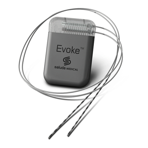
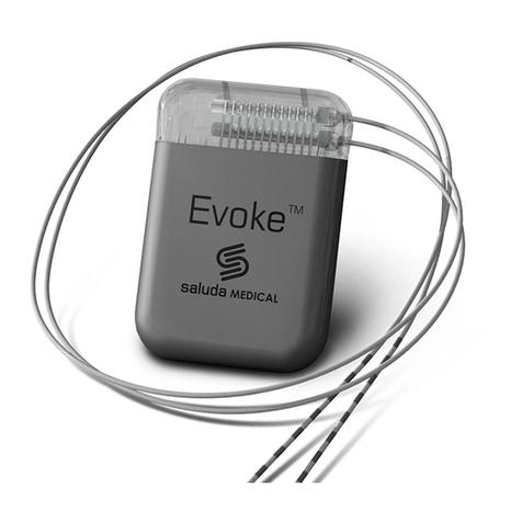
SALUDA MEDICAL Evoke SCS System Instructions for use

Evoke® SCS System Clinical Manual
CLIN-UMAN-005175 Revision: 9.00 Page 1 of 101
Evoke® SCS System Clinical Manual
Use of the Evoke Clinical Interface (CI) and Clinical Programming
Application (CPA) with the Evoke Clinical System Transceiver (CST) for
programming the Evoke SCS System

Evoke® SCS System Clinical Manual
CLIN-UMAN-005175 Revision: 9.00 Page 2 of 101
Table of Contents
1 DESCRIPTION ................................................................................................................... 5
1.1 THE CONCEPT OF ECAP-CONTROLLED CLOSED-LOOP SCS ............................................................ 5
1.2 STIMULATION FEATURES ....................................................................................................... 5
1.3 MEASUREMENT FEATURES .................................................................................................... 6
1.4 SYSTEM COMPONENTS ......................................................................................................... 8
2 INDICATION FOR USE ..................................................................................................... 10
3 CONTRAINDICATIONS .................................................................................................... 10
4 SAFETY INFORMATION ................................................................................................... 10
4.1 PRECAUTIONS ................................................................................................................... 10
5 INTRODUCTION .............................................................................................................. 12
5.1 EVOKE CLINICAL INTERFACE (CI) ........................................................................................... 12
5.2 EVOKE CLINICAL SYSTEM TRANSCEIVER (CST) ......................................................................... 12
6 CLINICAL INTERFACE – GENERAL PROGRAMMING USING THE CPA ................................. 13
6.1 CONNECTING THE CI TO THE CST AND ECLS/CLS .................................................................... 13
6.2 SET STIMULATOR TIME ........................................................................................................ 15
6.3 CHECK STIMULATOR BATTERY VOLTAGE .................................................................................. 16
6.4 RETRIEVE OR SET THE PATIENT ID AND PATIENT ZONE ............................................................... 16
6.5 MEASURE ELECTRODE IMPEDANCES ....................................................................................... 18
6.6 SET UP LEAD ORIENTATION .................................................................................................. 19
6.7 PROGRAMMING OVERVIEW ................................................................................................. 20
6.8 CHOOSE THE STIMULATION ELECTRODES AUTOMATICALLY .......................................................... 20
6.9 START AND STOP STIMULATION WITH CLOSED-LOOP DISABLED .................................................... 21
6.10 SET UP ECAP MEASUREMENT .............................................................................................. 23
6.11 SET UP CLOSED-LOOP STIMULATION ...................................................................................... 29
6.12 SET APPROPRIATE LIMITS AND INCREMENTS ............................................................................. 30
6.13 ENABLE CLOSED-LOOP STIMULATION ..................................................................................... 31
6.14 START AND STOP STIMULATION WITH CLOSED-LOOP ENABLED ..................................................... 33
6.15 SAVE A PROGRAM TO THE STIMULATOR .................................................................................. 34
6.16 CREATE A NEW PROGRAM OR USE PROGRAMMING FEATURES AND SETTINGS .................................. 36
6.17 DISCONNECT FROM THE STIMULATOR AND CLOSE THE CPA ........................................................ 36
7 CLINICAL INTERFACE – PROGRAMMING FEATURES ........................................................ 37
7.1 STIMULATION WAVEFORM .................................................................................................. 37
7.2 CLEARCAP ...................................................................................................................... 38
7.3 CURRENT STEERING ........................................................................................................... 39
7.4 MEASUREMENT ELECTRODE SCAN ......................................................................................... 40
7.5 INTERLEAVED STIMULATION ................................................................................................. 45
7.6 ACTIVATION PLOT LEVELS .................................................................................................... 49
7.7 DATA FILES ...................................................................................................................... 50
7.8 NEUROPHYSIOLOGICAL MEASUREMENTS ................................................................................ 51
7.9 ADDITIONAL IMPEDANCE MEASUREMENTS .............................................................................. 57
7.10 PATIENT SURVEY ............................................................................................................... 57
8 CLINICAL INTERFACE – SETTINGS GUIDE ......................................................................... 59
8.1 STIMULATION SETTINGS MENU ............................................................................................. 59
8.2 MEASUREMENT AND FEEDBACK SETTINGS MENU ...................................................................... 60

Evoke® SCS System Clinical Manual
CLIN-UMAN-005175 Revision: 9.00 Page 3 of 101
8.3 ELECTRODE SELECTION MODES ............................................................................................. 61
8.4 CLS MENU ....................................................................................................................... 62
8.5 NAVIGATION MENU ........................................................................................................... 65
8.6 SETTINGS SCREEN .............................................................................................................. 65
8.7 ALERT AND ERROR DISPLAY .................................................................................................. 68
9 INTRA-OPERATIVE PROGRAMMING WITH THE CI ........................................................... 70
9.1 CONNECT THE INTRAOPERATIVE CABLE TO THE ECLS ................................................................. 70
9.2 CONFIRM OPTIMAL LEAD PLACEMENT .................................................................................... 71
9.3 CONFIRM CLS CONNECTION ................................................................................................ 72
10 POST-OPERATIVE PROGRAMMING PROCEDURES ........................................................... 73
11 PREPARE THE ECLS FOR THE TRIAL STIMULATION PERIOD .............................................. 73
11.1 CONNECT THE LEAD OR LEAD EXTENSION TO THE LEAD ADAPTER .................................................. 73
11.2 CONNECT THE LEAD ADAPTER TO THE ECLS ............................................................................. 75
11.3 PLACE THE ECLS INTO THE CASE ........................................................................................... 76
11.4 CHARGE THE ECLS BATTERY ................................................................................................. 76
11.5 SECURE THE ECLS FOR THE TRIAL STIMULATION PERIOD ............................................................. 77
12 BEHAVIOUR OF THE STIMULATOR WHEN ALERTS OCCUR ............................................... 77
12.1 OUT OF COMPLIANCE ......................................................................................................... 77
12.2 REFERENCE CLOCK ERROR .................................................................................................... 78
12.3 ELECTRODE DISCONNECTED ................................................................................................. 78
12.4 CURRENT AT MAXIMUM ...................................................................................................... 78
12.5 CLIPPING ......................................................................................................................... 78
13 EVOKE PATIENT CONTROLLER ........................................................................................ 79
13.1 PAIR EPC TO STIMULATOR .................................................................................................. 79
14 EVOKE CHARGER ............................................................................................................ 80
14.1 STIMULATION DURING CHARGING ......................................................................................... 80
15 PATIENT EDUCATION AND ID CARD ................................................................................ 81
16 MAINTENANCE OF THE EVOKE CI AND EVOKE CST .......................................................... 82
16.1 MAINTENANCE OF THE EVOKE CI .......................................................................................... 82
16.2 MAINTENANCE OF THE EVOKE CST ....................................................................................... 82
16.3 UPDATING THE EVOKE CI SOFTWARE .................................................................................... 82
17 DISPOSAL OF DEVICES .................................................................................................... 83
18 TROUBLESHOOTING ....................................................................................................... 83
19 PACKAGE CONTENTS ...................................................................................................... 87
20 TECHNICAL SPECIFICATIONS ........................................................................................... 87
20.1 DEVICE SPECIFICATIONS ...................................................................................................... 87
20.2 WIRELESS COMMUNICATION ............................................................................................... 89
20.3 ELECTROMAGNETIC INTERFERENCE ........................................................................................ 89
20.4 FEDERAL COMMUNICATIONS COMMISSION (FCC) ................................................................... 93
21 GLOSSARY ...................................................................................................................... 94
22 SYMBOLS ....................................................................................................................... 99
23 CONTACT US ................................................................................................................ 101

Evoke® SCS System Clinical Manual
CLIN-UMAN-005175 Revision: 9.00 Page 4 of 101
Trademarks
Saluda, Evoke, and the Saluda Medical logo are registered trademarks of Saluda Medical Pty
Ltd.
Copyright © 2022 Saluda Medical Pty Ltd, Sydney, Australia. All rights reserved.
Refer to the Evoke SCS System Surgical Guide for:
•System warnings and precautions
•Instructions on the implantation of the Evoke System components
•Other system component device specifications and package contents
Refer to the Evoke SCS System User Manual for:
•Instructions on the use of the Evoke Patient Controller (EPC) and Evoke Charger.
Manuals are accessible at http://www.saludamedical.com/manuals.

Evoke® SCS System Clinical Manual
CLIN-UMAN-005175 Revision: 9.00 Page 5 of 101
1 Description
The Saluda® Medical Evoke® SCS System is a Spinal Cord Stimulation (SCS) system that
incorporates ECAP-controlled closed-loop stimulation for the management of chronic,
intractable pain. The Evoke System measures evoked compound action potentials (ECAPs) and
may be programmed to deliver either ECAP-controlled closed-loop SCS or fixed-output open-
loop SCS.
The Evoke Clinical Interface (CI) and Evoke Clinical System Transceiver (CST) enable the
programming of the implantable Closed-Loop Stimulator (CLS) and the non-implantable
External Closed-Loop Stimulator (eCLS).
The Evoke System may be used in conjunction with other pain management therapies, as
determined by the physician.
1.1 The concept of ECAP-controlled closed-loop SCS
The Evoke System uses ECAP amplitude to measure the patient’s neural response and provide
closed-loop (CL) SCS. The ECAP amplitude is a measure of the spinal cord activation or number
of dorsal column fibers in the spinal cord that are activated by a stimulation pulse. When
closed-loop is enabled, the system automatically varies the stimulation current for every pulse
to maintain consistent spinal cord activation during physiological changes and movement.
Figure 1.1, below, depicts the concept of an ECAP-controlled closed-loop system. Following a
stimulation pulse, the amplitude of the ECAP that is generated in the spinal cord by that
stimulus is recorded. The ECAP amplitude is compared to the selected target and then used to
automatically adjust the current of the next stimulus to maintain a consistent ECAP amplitude.
Figure 1.1: ECAP-Controlled Closed-Loop SCS.
1.2 Stimulation Features
The Evoke System provides the following advanced stimulation options.
1.2.1 Closed-loop SCS
When closed-loop is enabled, the system uses feedback of the ECAP amplitude to automatically
adjust the stimulation current of every pulse to maintain a target activation level. This ensures
consistent dorsal column activation during physiological changes and movement.

Evoke® SCS System Clinical Manual
CLIN-UMAN-005175 Revision: 9.00 Page 6 of 101
1.2.2 Open-loop SCS
When closed-loop is disabled, the system delivers a fixed-output of stimulation current, while
continuing to measure ECAP amplitude. Since the stimulation current is fixed, the activation
level will vary as the spinal cord moves relative to the stimulation electrodes.
1.2.3 Current steering
Multiple stimulation electrodes can be used simultaneously, with a scaled portion of the total
current delivered to each electrode. This enables more targeted stimulation between
electrodes.
1.2.4 Interleaved stimulation
Two or more stimulation configurations can be used concurrently, with the system
automatically cycling through each configuration. Each interleaved configuration (stimulation
set) can target a different area of the patient’s pain.
1.2.5 Multiple waveform options
The stimulation waveform consists of constant current, actively charge-balanced pulses and can
be customized by the selection of pulse shape (biphasic or triphasic), polarity (negative or
positive first), amplitude (ratio of stimulation current between stimulation sets) and pulse
timing (pulse width, frequency, interphase gap and inter-stimulus interval).
1.3 Measurement Features
The Evoke System supports the following types of measurements and data analysis. Refer to
the Evoke SCS System Clinical Data Viewer User Manual for additional information on data
analysis.
1.3.1 ECAP Measurements
ECAP amplitude is a measure of spinal cord activation and is used by the stimulator for closed-
loop stimulation. ECAP signals can be viewed in the CPA during a programming session (to
objectively observe the patient’s neural response, independent of the patient’s subjective
reports), and also later analyzed in the CDV for their objective features (such as shape, latency,
conduction velocity and amplitude).
1.3.2 ClearCAP™
ClearCAP is used to reduce the artefact recorded during measurement by cancelling the
artefact from the stimulation and return electrodes; this feature is best used when optimizing
ECAP measurement (see Section 7.2). ClearCAP is labeled as ‘Virtual Ground’ in the CPA.
1.3.3 Therapeutic window
During a programming session, the CPA may be used to record the ECAP amplitude at the
patient’s threshold, comfort and maximum levels, which may then be used to define the
patient’s therapeutic window.

Evoke® SCS System Clinical Manual
CLIN-UMAN-005175 Revision: 9.00 Page 7 of 101
1.3.4 Detection of late response
Late responses are neural responses resulting from dorsal root activation. Late responses have
longer latency than ECAPs and they do not propagate along the spinal cord. They can be viewed
in the CPA during a programming session or reviewed later in the CDV.
1.3.5 Activation Plot and Sensitivity
The CPA displays a plot of activation (ECAP amplitude) as a function of stimulus current for one
or more postures. The sensitivity of a patient’s neural response to changes in stimulation
current can be measured from the slope of the activation plot.
1.3.6 Data recording and patient compliance
While the patient is using their stimulator, various usage and measurement data are recorded
on the stimulator. This data includes stimulation status (on/off), closed-loop status
(enabled/disabled), ECAP amplitude, stimulation current, and patient interactions with the
device. This data is downloaded via the CPA and can be viewed in the CDV.
1.3.7 Neural response profile (NRP)
The neural response profile is a set of objective measures characterizing the spinal cord
activation levels experienced by the patient while using their stimulator. Activation level (ECAP
amplitude) is continuously recorded and compressed into histogram bins on the stimulator for
later analysis on the CDV.
1.3.8 Conduction velocity (CV)
ECAP recordings can be used to determine the conduction velocity of the dorsal column fibers
being stimulated. ECAPs are recorded using the CPA and analyzed using the CDV to calculate
their velocity. Changes in the population of fiber sizes activated and fiber properties may be
detected through changes in CV.
1.3.9 Chronaxie and rheobase (strength-duration curve)
ECAP amplitudes recorded at different stimulation pulse widths can be used to objectively
calculate chronaxie and rheobase for fibers activated during spinal cord stimulation. Changes in
axonal excitability or distance from electrode may be detected through changes in chronaxie or
rheobase.
1.3.10 Lead offset measurement
The vertical alignment of two implanted leads may be estimated using the lead offset
measurement feature in the CPA. The measured offset between two leads may be used to
guide the choice of stimulation and measurement electrodes.

Evoke® SCS System Clinical Manual
CLIN-UMAN-005175 Revision: 9.00 Page 8 of 101
1.4 System Components
1.4.1 Evoke Closed-Loop Stimulator (CLS)
Ref No. 3002
The Evoke Closed-Loop Stimulator (CLS) is a totally implanted spinal cord stimulator that
connects to the 12C Percutaneous Leads and is implanted under the skin for long-term therapy.
The CLS delivers either closed-loop or open-loop stimulation through the leads and measures
the neural response to stimulation. A port plug is provided with the CLS, for insertion into an
unused CLS port when only one lead is implanted.
1.4.2 Evoke External Closed-Loop Stimulator (eCLS)
Ref No. 3036
During the trial stimulation period, the 12C Percutaneous Leads are connected to the Evoke
External Closed-Loop Stimulator (eCLS). The eCLS is an external stimulator used for
intraoperative testing and during the trial stimulation period. The eCLS delivers either closed-
loop or open-loop stimulation through the leads and measures the neural response to
stimulation.
1.4.3 Evoke eCLS Case
Ref No. 3035
The Evoke eCLS Case is used by the patient to house the eCLS during the trial stimulation
period. The kit also includes two lead adapters to connect the leads or lead extensions to the
eCLS
1.4.4 Evoke 12C Percutaneous Lead Kit, 60cm and 90cm
Ref No. 3008/3016/3009/3017
The Evoke 12C Percutaneous Leads are placed in the epidural space overlying the spinal cord
and are connected to an eCLS for a trial stimulation period, or to a CLS for long-term therapy.
One or two leads, each with 12 electrodes, are implanted. The lead kit is provided with two
suture anchors and an active anchor with torque wrench to secure the leads, and surgical
accessories (epidural needle, tunneling tool, and three stylets) for use during lead placement.
Trial leads (Ref No. 3016 and 3017) are provided without the active anchor and torque wrench.
1.4.5 Evoke 12C Lead Extension Kit, 55cm
Ref No. 3011
The Evoke 12C Lead Extensions are used trialing a permanently implanted lead, where the
extension is externalized for connection to an eCLS.
1.4.6 Evoke Intraoperative Cable Kit
Ref No. 3034

Evoke® SCS System Clinical Manual
CLIN-UMAN-005175 Revision: 9.00 Page 9 of 101
The Evoke Intraoperative Cable allows the surgeon to connect the eCLS to the implanted leads
for intra-operative testing.
1.4.7 Evoke Patient Controller (EPC)
Ref No. 3040
The Evoke Patient Controller (EPC) allows the patient to control their therapy and actively
monitors the stimulator battery status and other elements of the system. The EPC and the
stimulator communicate with each other wirelessly.
1.4.8 Evoke Charger
Ref No. 3006
The Evoke Charger allows the patient to recharge the battery in a CLS. The Charger coil
(attached to the Charger) is placed over the CLS and charge is transferred to the CLS through
thin clothing and the skin. The Charger kit also includes a power adapter for recharging the
Charger.
1.4.9 Evoke Accessory Belt
Ref No. 3039
The Evoke Accessory Belt is an elastic belt with a pouch to hold an eCLS or Charger coil.
1.4.10 Evoke Clinical Interface (CI)
Ref No. 3024
The Evoke Clinical Interface (CI) is a tablet computer with a preinstalled programming
application (the Clinical Programming Application, CPA) used by the clinician to adjust the
therapy settings of the Evoke CLS and eCLS.
1.4.11 Evoke Clinical System Transceiver (CST)
Ref No. 3004
The Evoke Clinical System Transceiver (CST) is a plug-in device (USB connection) that enables
exchange of information wirelessly between the CI and the stimulator.

Evoke® SCS System Clinical Manual
CLIN-UMAN-005175 Revision: 9.00 Page 10 of 101
2 Indication for use
The Saluda Medical Evoke SCS System is indicated as an aid in the management of chronic
intractable pain of the trunk and/or limbs, including unilateral or bilateral pain associated with
the following: failed back surgery syndrome, intractable low back pain and leg pain.
3 Contraindications
The Evoke SCS System should not be used in patients who:
•Do not receive effective pain relief during trial stimulation.
•Are unable to operate the Evoke SCS System.
•Are unsuitable surgical candidates.
4 Safety Information
Although FDA has determined that the probable benefits outweigh the probable risks, there
remains some uncertainty on the long term systemic toxicity risks of the leads, lead extensions,
and anchors of the device. As a condition of approval, FDA is requiring the manufacturer to
provide additional long term systemic toxicity information.
For general system warnings and precautions refer to the Evoke SCS System Surgical Guide,
accessible at http://www.saludamedical.com/manuals.
The Evoke CI is based on a tablet computer. For non-therapy specific warnings and precautions
on this product refer to the device manual accompanying the CI tablet .
4.1 Precautions
4.1.1 Unsupported software applications
Do not load additional software applications onto the Evoke CI. The Evoke CI has all the
necessary software required to interact with and program the Evoke SCS System from Saluda
Medical. Other applications could interfere in unpredictable ways with the programming
software installed and affect the delivery of therapy for patients. Any required software
installations shall be supported directly by Saluda Medical representatives or via detailed
instructions concerning specific installations as required.
4.1.2 Unsupported hardware
Do not connect any device to the Evoke CI other than the supplied: keyboard, power
adapter and Evoke CST. Do not connect the Evoke CST to any device other than a Saluda
Medical supplied Evoke CI. Unsupported hardware could interfere in unpredictable ways with
the programming software installed and affect the delivery of therapy for patients.

Evoke® SCS System Clinical Manual
CLIN-UMAN-005175 Revision: 9.00 Page 11 of 101
For data file extraction, it is permissible to use an external USB memory stick that has passed a
screening check by an up-to-date anti-virus software application, but no files should be
transferred onto the CI unless otherwise instructed by Saluda Medical to do so.
4.1.3 Shared IT networks
Network connection (via Wi-Fi) is only permitted to secure networks. Connecting to unsecure
networks could lead to the modification of the CI system or software that interfere in
unpredictable ways with the programming software installed and affect the delivery of therapy
for patients.
4.1.4 Modification of the programming software
Do not attempt to modify the Clinical Programming Application (CPA) software which
comes preinstalled on the CI for the programming of Saluda Medical neurostimulators. Any
deletion or modification of files associated with the CPA could adversely affect the
system's ability to effectively adjust therapy for patients.
Required software upgrades will be supported directly by Saluda Medical representatives or via
detailed instructions concerning specific upgrades as required. Additionally, any stimulator
software upgrades will be fully supported by Saluda Medical representatives – do not attempt
to modify the stimulator software without Saluda Medical’s instruction.
4.1.5 Non-sterile components
DO NOT STERILIZE the CI, CST, eCLS, EPC or Charger; these items are not to be sterilized and
doing so could irrevocably damage the devices.
4.1.6 Clinical staff training
Clinical staff using the CI/CST to program the Evoke SCS System must be adequately trained
in the programming of SCS systems generally. Additionally, clinical staff programming the Evoke
SCS System should have read the instructions within this manual. A poor understanding of the
programming of SCS systems generally, and the Evoke system specifically, could cause
unpleasant or painful stimuli for patients.
4.1.7 Electromagnetic interference (EMI)
As the CI communicates via the CST to the neurostimulator (eCLS or CLS) wirelessly, the quality
of this connection can be adversely affected by some types of electrical equipment that
generate EMI. Such equipment should be avoided where possible when programming and/or
suspected if communication between stimulator and CI/CST is poor. Examples of such
equipment found in clinical environments include but are not limited to: Mobile phones,
electro-surgery tools, electromagnets, radiofrequency identification devices and emergency
vehicle/services radios.

Evoke® SCS System Clinical Manual
CLIN-UMAN-005175 Revision: 9.00 Page 12 of 101
4.1.8 General precautions for the CI
The CI is a critical piece of equipment to enable the delivery of therapy. Always handle it with
care and regularly inspect the device for damage and/or impaired functioning. Never modify
the CI in any way. If you have concerns about the integrity of the CI/CST, contact Saluda
Medical representatives to arrange repair or replacement. The CI runs on a rechargeable
battery and can be used wirelessly or while plugged in via the power adapter supplied. Care
should be taken to keep the CI well charged so it can be used in clinical environments where
plug sockets are not readily available. Always have a spare charged CI available in case of
malfunction.
4.1.9 Lead Extension
The Lead Extension should only be used as part of a trial system, to connect the lead to the
eCLS (via the lead adaptor). It should not be implanted for connection to an implanted CLS.
5 Introduction
5.1 Evoke Clinical Interface (CI)
The CI is a tablet computer. For full specifications and instructions for use of the the tablet
computer refer to the device manual accompanying the CI tablet. The computer is not
physically modified in any way. The CI operates on the Microsoft Windows platform. The CI is
supplied with the software necessary for programming Saluda Medical stimulators pre-
installed, and no other software should be installed on the device.
Upon starting and logging in to the CI, the user will immediately find a program icon . This
will lead the user into the Clinical Programming Application (CPA) that enables programming of
either the Evoke eCLS or CLS.
Note: Login password for the CI will be provided by Saluda Medical representatives and
cannot be changed. All potential CI operators should be made aware of this password.
5.2 Evoke Clinical System Transceiver (CST)
The CST is a radio telemetry device that enables communication between the CI and the
stimulator (eCLS or CLS). Commands generated through the CPA loaded on the CI are sent to
the stimulator and data is received back from the stimulator to display in the CPA via the CST.
The CST is connected to the CI via a USB connector and receives power from the CI via this link.

Evoke® SCS System Clinical Manual
CLIN-UMAN-005175 Revision: 9.00 Page 13 of 101
6 Clinical Interface – General programming using the CPA
6.1 Connecting the CI to the CST and eCLS/CLS
To program and download data from the eCLS or CLS, communication must first be established.
The CST connects to the CI to communicate using a radio signal transmitted to the eCLS or CLS.
1. Turn on the CI and login to the ‘Saluda’ account.
2. Check that the time and date on the CI are correct (bottom right corner of CI screen).
Refer to the CI instructions (see Section 5.1 for link) to change the time and date.
3. Connect the CST to the CI with the USB connection. See Figure 6.1.
Figure 6.1: Connecting the CST to the CI.
4. Position the CST near the stimulator and double-touch the Evoke Clinical Programing
Application (CPA) icon to start the CPA (see Figure 6.2 for the main screen layout).
Note: The CST can link with the stimulator within a 1.0 m (3.3 ft) radius.
Note: Electromagnetic interference can affect the quality of this wireless link; see
Section 4.1.7 - Electromagnetic interference (EMI).

Evoke® SCS System Clinical Manual
CLIN-UMAN-005175 Revision: 9.00 Page 14 of 101
Figure 6.2: Functional layout of the CPA main screen.
5. Choose the appropriate Visit Name from the dropdown menu (see Figure 6.3).
6. Touch Connect to Implant to search for nearby stimulators (see Figure 6.3).
Caution: Before connecting the CPA to the stimulator, ensure that you have a
magnet and paired EPC (see Section 13.1) available at all times during the programming
session in case they are needed to stop stimulation (refer to the Evoke SCS System User
Manual).
Stimulation Settings
(hidden)
ECAP measurement bar
graph
Side
Bar
Electrode Display Window
(‘Stimulation Settings’ and ‘ECAP
Measurement Settings’ hidden)
Stimulation
Current Control
ECAP measurement and
Current rolling plot
Notes
Error Log
Count
Stimulation sets
Patient
ID/Patient
zone
ECAP Measurement
Settings (hidden)
Stored
programs
ECAP
Display
Electrode Selection
Mode
CLS Menu and RF
communication
Active
program
Navigation Menu

Evoke® SCS System Clinical Manual
CLIN-UMAN-005175 Revision: 9.00 Page 15 of 101
Figure 6.3: Location of the Visit Name dropdown menu and Connect to Implant button.
7. Touch the stimulator serial number that you wish to connect to.
8. The CPA will connect to the stimulator and retrieve any patient data and programs.
Note: Depending on the amount of data saved on the device this could take several
minutes. Downloading can be cancelled but this is not recommended as any system
error and device usage logs will be missed.
9. The CPA will display the electrode display window when it has successfully connected
and downloaded data from the stimulator.
Note: When the CPA connects to a stimulator it will attempt to download three log files
from the stimulator. If any logs cannot be downloaded an error message will be
displayed on the ECAP amplitude and current rolling plot (see Section 8.7). To download
the logs manually, such as when download fails, refer to Section 8.4.
6.2 Set stimulator time
The stimulator time is automatically synchronized to the CI time during connection.
1. Check that the time and date on the CI are correct (top left corner of CPA screen, Figure
6.2). Refer to the CI instructions (see Section 5.1 for link) to change the time and date.
2. Touch the CLS icon to open the CLS menu.
3. Touch Sync Time in the CLS menu to set the stimulator time to the CI time (if the time is
Visit Name
dropdown menu
Connect to
Implant button

Evoke® SCS System Clinical Manual
CLIN-UMAN-005175 Revision: 9.00 Page 16 of 101
not already synchronized).
Note: The time error between the CI and stimulator is displayed in brackets.
Note: If out of sync, a red ‘clock’ icon will be displayed in the CLS icon window
and the time error between CI and stimulator is displayed in brackets in the CLS menu.
6.3 Check stimulator battery voltage
The CLS or eCLS battery voltage are indicated on the CLS icon with a white bar and
voltage (3.25 to 4.10 V; Figure 6.4). If the battery voltage is low (<25 % full) the bar will be red.
Refer to the Evoke SCS System User Manual for instructions on charging the CLS battery or
Section 11.4 for charging the eCLS battery.
Figure 6.4: CLS icon with stimulator battery voltage indicator.
6.4 Retrieve or set the Patient ID and Patient Zone
6.4.1 For an existing patient
1. On connection to the stimulator the Patient ID and Patient Zone are retrieved and
displayed under the CLS icon (see Figure 6.5).
Figure 6.5: CLS Icon with Patient ID and Zone underneath.
2. Check that the correct Patient ID and Patient Zone have been retrieved.
6.4.2 For a new patient
1. For a new patient, touch the Patient ID box under the CLS icon (see Figure 6.5).
2. Delete any existing text and enter the new Patient ID.
3. Touch the Done button that appears above the Patient ID when you finish typing (see
Figure 6.6).
Stimulator
battery
indicator
Patient ID
field
Patient
Zone field

Evoke® SCS System Clinical Manual
CLIN-UMAN-005175 Revision: 9.00 Page 17 of 101
Figure 6.6: CLS Icon with Patient ID and Done button.
Note: If you do not touch the Done button, the Patient ID will be automatically updated
in the stimulator when you start stimulation.
4. Navigate to the settings page by opening the navigation menu and touching
Settings (see Figure 6.7). Select the appropriate Patient Zone (see Figure 6.8).
5. Return to the CLS programming page by opening the navigation menu and
touching Programming (see Figure 6.7).
Figure 6.7: Navigation menu.

Evoke® SCS System Clinical Manual
CLIN-UMAN-005175 Revision: 9.00 Page 18 of 101
Figure 6.8: Settings menu with Patient Zone dropdown menu highlighted.
6.5 Measure electrode impedances
Measure the electrode impedances to determine if all connections are intact between leads,
any lead adapters, and the stimulator.
1. Touch the Impedance icon .
Note: The icon will spin during the measurement and stop once it is complete.
2. The impedances on the 24 electrodes and CLS case (E25) will be shown in the electrode
display window (see Figure 6.9).
Patient Zone
dropdown menu

Evoke® SCS System Clinical Manual
CLIN-UMAN-005175 Revision: 9.00 Page 19 of 101
Figure 6.9: Impedances displayed on the 24 electrodes and CLS case (E25).
3. An electrode with a cross through it has high impedance (> 4000 Ω) and may
be disconnected. A disconnected electrode shows an impedance of ∞ and cannot be
used for stimulation. Measurement electrodes that are disconnected will not record
valid ECAPs.
Note: The CLS case cannot be used for stimulation and may show as high impedance
(> 4000 Ω). The CLS case may be used for recording even if high impedance is shown.
4. Electrodes with a lightning bolt through them may be shorted (< 50 Ω) and care
should be taken when programming.
Caution: If the electrodes show an open circuit (i.e. disconnected):
•Wipe any blood or fluid off the lead connection contacts.
•If the system is fully implanted, a high impedance may indicate that the lead is
broken or dislodged from the header and the patient may require revision
surgery if stimulation cannot be adequately reprogrammed.
Note: When connected to an eCLS the CLS case is disconnected and cannot be used.
6.6 Set up lead orientation
1. Touch the handle at the bottom of the lead image to move it up, down, or switch sides
to a position that reflects the lead location in the most recent fluoroscopy image (see
Figure 6.10). This will aid in determining the best stimulation and measurement
electrode combination.
2. If a recent fluoroscopy image is not available then use the lead offset test to estimate
the vertical alignment of the implanted leads (see Section 7.8.4).

Evoke® SCS System Clinical Manual
CLIN-UMAN-005175 Revision: 9.00 Page 20 of 101
Figure 6.10: You can drag the leads up, down or switch sides.
6.7 Programming overview
1. Test stimulation from several electrodes (see Section 6.8 and 6.9) and ask the patient to
report where they feel paresthesia.
2. Determine the stimulation electrodes and parameters that give the best paresthesia
coverage of the patient’s dermatomal pain area(s).
3. Determine the settings that provide a good measurement of the neural response (ECAP)
to stimulation (see Section 6.10).
4. Determine the settings for optimum closed-loop stimulation (see Section 6.11 and 6.13).
5. Save the program to the eCLS/CLS memory (see Section 6.15) and proceed to set up a
maximum of four programs.
6.8 Choose the stimulation electrodes automatically
1. Stop stimulation if stimulation is running.
2. Change the Electrode Selection Mode icon (see Figure 6.2) until the Automatic Electrode
Selection icon is displayed.
3. In the electrode display window, touch the electrode that you wish to use as the
stimulation electrode .
4. Touch the stimulation electrode again to cycle through electrode configurations.
Tripolar: 1 lead
Bipolar: 1 lead
Tripolar: 2 leads
Bipolar: 2 leads
Other manuals for Evoke SCS System
2
Table of contents
Other SALUDA MEDICAL Medical Equipment manuals