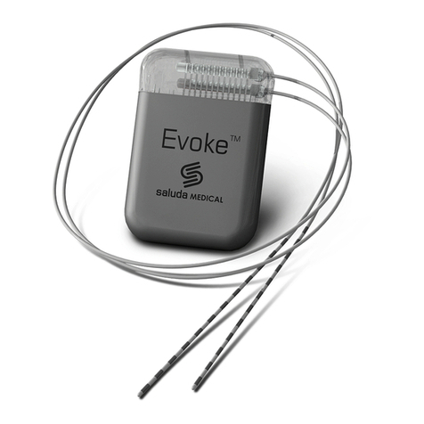
SALUDA MEDICAL Evoke SCS System User manual

Document Reference: ENG-UMAN-000730 Revision: 6.00 Page 1 of 40
Evoke™ SCS System Surgical Guide
Instructions for the use and implantation of the Evoke™ SCS System
CAUTION – Investigational Device.
Limited by Federal (or United States) law to investigational use.

Document Reference: ENG-UMAN-000730 Revision: 6.00 Page 2 of 40
Table of Contents
1DESCRIPTION ............................................................................................................ 4
2INTENDED USE .......................................................................................................... 5
3CONTRAINDICATIONS ............................................................................................... 5
4SAFETY INFORMATION.............................................................................................. 6
WARNINGS .....................................................................................................................6
PRECAUTIONS ..................................................................................................................8
POTENTIAL RISKS............................................................................................................10
5PERCUTANEOUS LEAD IMPLANT PROCEDURE .......................................................... 12
OVERVIEW ....................................................................................................................12
PERCUTANEOUS LEAD PLACEMENT ....................................................................................12
6ANCHOR THE LEAD.................................................................................................. 15
POSITION THE ANCHOR ....................................................................................................15
SECURE THE ANCHOR.......................................................................................................15
CREATE A STRAIN RELIEF LOOP IN THE LEAD ..........................................................................17
7LEAD TUNNELING AND CLS IMPLANT PROCEDURE................................................... 17
LOCATE AND CREATE A POCKET FOR THE CLS........................................................................17
TUNNEL THE LEAD PROXIMAL CONNECTORS AND CONNECT TO THE CLS .....................................17
ANCHOR THE CLS, CLOSE AND DRESS THE INCISIONS ..............................................................21
POST-OPERATIVE PROCEDURES.........................................................................................21
8TRIAL WITH A TEMPORARY PERCUTANEOUS LEAD .................................................. 22
REMOVE THE STYLET AND EPIDURAL NEEDLE.........................................................................22
ANCHOR THE LEAD,CLOSE AND DRESS THE INCISIONS .............................................................22
POST-OPERATIVE PROCEDURES.........................................................................................22
REMOVING A PERCUTANEOUS LEAD AT THE END OF A TRIAL ...................................................22
9REVISION, REPLACEMENT AND EXPLANT SURGERY.................................................. 22
OPEN THE COMPONENT SITES............................................................................................23
PERCUTANEOUS LEADS ....................................................................................................23
CLS .............................................................................................................................23
10 INTRA-OPERATIVE TESTING ..................................................................................... 24

Document Reference: ENG-UMAN-000730 Revision: 6.00 Page 3 of 40
CONNECT THE LEAD TO THE LEAD ADAPTER.......................................................................24
CONNECT THE LEAD ADAPTER CABLE TO THE LEAD ADAPTER EXTENSION..................................26
CONNECT THE LEAD ADAPTER EXTENSION TO THE ECLS.......................................................26
CONFIRM OPTIMAL LEAD PLACEMENT..............................................................................27
DISCONNECTING THE LEAD ADAPTER FROM THE LEAD ADAPTER CABLE....................................28
DISCONNECT THE LEAD FROM THE LEAD ADAPTER ..............................................................29
11 STERILIZATION ........................................................................................................ 30
12 PATIENT ID CARD .................................................................................................... 30
13 MAINTENANCE OF THE EVOKE™ ECLS...................................................................... 30
14 PACKAGE CONTENTS............................................................................................... 31
15 SPECIFICATION........................................................................................................ 33
EVOKE™CLS .............................................................................................................33
EVOKE™ECLS ...........................................................................................................34
EVOKE™12C PERCUTANEOUS LEAD (INCLUDES TRIAL LEADS)..............................................35
SURGICAL ACCESSORIES ...............................................................................................35
EVOKE™CI SPECIFICATIONS ..........................................................................................37
EVOKE™CST SPECIFICATIONS .......................................................................................37
16 GLOSSARY AND SYMBOLS ....................................................................................... 38
GLOSSARY .................................................................................................................38
SYMBOLS...................................................................................................................39
17 CONTACT US ........................................................................................................... 40
Trademarks
Saluda, Evoke™ and the Saluda logo are registered trademarks of Saluda Medical Pty Ltd.
Copyright statement
This work is copyright and may not be copied, reproduced or retransmitted without written
permission from Saluda Medical Pty Ltd.
Copyright © 2017 Saluda Medical Pty Ltd, Sydney, Australia. All rights reserved.

Document Reference: ENG-UMAN-000730 Revision: 6.00 Page 4 of 40
1Description
The Evoke™ System is a Spinal Cord Stimulation (SCS) system that can measure the Evoked
Compound Action Potential (ECAP) and may provide consistent stimulation based on the
subjects neural response during physiological changes and movement by automatically
adjusting the level of stimulation current required to meet the subject’s requested target
level.
The Evoke™ System may be used in conjunction with other pain management therapies, as
determined by the physician.
The Evoke™ System comprises several key components to deliver the therapy.
Table 1.1: Description of Evoke™ System Components
Name: Evoke™ Closed Loop Stimulator (CLS)
Ref No.: 0002
The Evoke™ Closed Loop Stimulator (CLS) is a totally implanted spinal cord stimulator that
connects to the leads and is implanted under the skin for long-term therapy. The CLS
delivers stimulation through the leads and measures the neural response to stimulation.
Name: Evoke™ External Closed Loop Stimulator (eCLS)
Ref No.:0020
During the trial stimulation period, the leads are connected to the Evoke™ External Closed
Loop Stimulator (eCLS). The eCLS is an external stimulator worn during the trial
stimulation period. The eCLS delivers stimulation through the leads and measures the
neural response to stimulation.
Name: Evoke™ 12C Percutaneous Leads
Ref No.:
0008, 0026 (permanent lead length 60 cm)
0016 (trial lead length 60 cm)
0009, 0027 (permanent lead length 90 cm)
0017 (trial lead length 90 cm)
The Evoke™ 12C Percutaneous Leads are placed in the epidural space overlying the spinal
cord and are connected to an eCLS for a trial stimulation period or to a CLS for long-term
therapy.
One or two leads with 12 electrodes on each lead are implanted.
Name: Evoke™ Lead Adapter Kit
Ref No.:0028
The Evoke™ Lead Adapter allows connection between the eCLS and the implanted leads.
Name: Evoke™ Clinical Interface (CI)
Ref No.:0024
The Evoke™ Clinical Interface (CI) is a tablet computer with a programming application
used by the clinician to adjust the therapy settings in the Evoke™ CLS or Evoke™ eCLS.

Document Reference: ENG-UMAN-000730 Revision: 6.00 Page 5 of 40
Name: Clinical System Transceiver (CST)
Ref No.:0004
The Clinical System Transceiver (CST) is a plug in device that enables exchange of
information wirelessly between the CI and the stimulator.
Name: Evoke™ Tunneling Tool Kit
Ref No.: 0012
The Evoke™ Tunneling Tool allows the subcutaneous threading of leads and/or extensions
either to an exit incision for the trial stimulation period or to the CLS.
Name: Evoke™ Spares Kit
Ref No.: 0015
The Evoke™ Spares Kit contains all items from the permanent lead kits except for the lead
itself, plus a CLS port plug and torque wrench.
Name: Epidural Needle 6.5” Kit
Ref No. 0014
The 6.5” Epidural Needle Kit is an optional extra long needle for larger patients in whom
the regular 4.5” needle supplied with the lead kits is too short to reach the epidural space.
2Intended Use
The Saluda Medical Evoke™ SCS System is indicated as an aid in the management of chronic
intractable pain of the trunk and/or limbs, including unilateral or bilateral pain associated
with the following: failed back surgery syndrome, intractable low back pain and leg pain.
3Contraindications
The Evoke™ System should not be used in patients who:
•Do not receive effective pain relief during trial stimulation
•Are unable to operate the system
•Are unsuitable surgical candidates

Document Reference: ENG-UMAN-000730 Revision: 6.00 Page 6 of 40
4Safety Information
Patients must be advised of the following warnings and precautions (sections 4.1 and 4.2):
Warnings
Diathermy
•Patients implanted with the Evoke™ System should not be subjected to shortwave,
microwave and/or therapeutic ultrasound diathermy.
•Diathermy generates energy that may cause heating at the lead site resulting in
damage to the CLS, tissue damage, severe injury or death.
Magnetic Resonance Imaging (MRI)
•As the Evoke™ System has not been tested for MRI compatibility, it is considered
MRI unsafe. Patients implanted with the Evoke™ System should not be subjected to
MRI as it may result in significant heating and/or tissue damage.
•MRI exposure can damage the CLS, potentially requiring device explantation and
replacement.
•MRI exposure may also induce currents through the leads and stimulator leading to
unintended stimulation, such as tingling, shocking, or jolting.
CT Scans
•Patients implanted with the Evoke™ System may experience a momentary increase
in stimulation when receiving a CT scan. Some patients have described this as
uncomfortable stimulation, jolting or a shocking sensation.
•Prior to a patient undergoing a CT scan, turn the neurostimulator off.
Electrosurgery
•Patients implanted with the Evoke™ System should not be subjected to
electrosurgical techniques, such as electrocautery, in close proximity to the Evoke™
System components.
oElectrosurgical devices generate energy that may cause tissue damage at the
lead site and result in severe injury.
oDamage may also occur to the CLS
Interference with implanted cardiac devices
•The Evoke™ System may interfere with other implanted stimulators with sensing
capabilities such as demand type pacemakers or cardioverter defibrillators.
•The effects of implanted stimulation devices on the Evoke™ System is unknown.
Stimulator damage
•If the CLS case is ruptured or pierced, then patient tissue may be exposed to battery
chemicals, which could lead to burns or tissue damage.
oDo not implant the CLS if the case is damaged.

Document Reference: ENG-UMAN-000730 Revision: 6.00 Page 7 of 40
Electromagnetic interference
•Strong electromagnetic fields may turn the stimulator off, cause uncomfortable or
jolting stimulation or affect communication with the EPC.
•Patients should be advised to avoid or turn stimulation off around:
oSecurity screeners such as those used at of department stores, public
buildings, and airports – patients should present their implantable device ID
card and request to go around the screener; but if they are required to go
through the screener they should turn stimulation off.
oPower lines or power generators.
oElectric steel furnaces and arc welders.
oLarge, magnetized stereo speakers.
oTag deactivators such as those found in retail stores and libraries.
Heat due to charging
•During charging, the Charger and/or CLS may become warm.
•Patients should not charge while sleeping or with the charging coil in contact with
their skin for prolonged periods as this may result in heating that can cause redness,
skin irritation or a burn.
•If patients experience pain or discomfort, they should cease charging and contact
their clinician.
Notification of an implanted stimulator prior to any other surgical procedures
•Some surgical procedures that use electrical current could affect the patient’s
implanted stimulator and leads, cause serious injury, and may damage the stimulator
•Patients should be advised to inform their clinician prior to any procedure that they
have an implanted stimulator so the procedure can be conducted without using
electric current near the implanted stimulator or leads.
Uncomfortable changes to the stimulation strength due to movement
•Any changes in posture may cause an uncomfortable change or a painful increase in
the stimulation strength patients feel.
•Patients should turn down the stimulation strength or turn off the stimulation before
making posture changes.
The Evoke™ System has not been tested for use in patients who are pregnant or
nursing.
The Evoke™ System has not been tested for use in patients under 18 years old.

Document Reference: ENG-UMAN-000730 Revision: 6.00 Page 8 of 40
Precautions
Physician training
•Implanting physicians should be trained in SCS procedures.
•Physicians should review this surgical manual before surgery.
Medical imaging
•MEG, PET, x-ray/fluoroscopy and diagnostic ultrasound are unlikely to affect the
Evoke™ System
Medical therapies
When used in close proximity to the Evoke™ System, the following medical therapies may
turn stimulation off or cause damage to the CLS:
oLithotripsy
oElectrocautery
oExternal defibrillation
oRadiation therapy (any damage to the device by radiation may not be
immediately detectable).
oUltrasonic scanning
oHigh-output ultrasound
oTENS
oPsychotherapeutic procedures (e.g. electroconvulsive therapy, transcranial
magnetic stimulation).
oLaser procedures
If the patient is required to undergo any of these therapies:
1. Turn off stimulation
2. Disconnect the eCLS if one is in use
3. Ensure all fields, electrodes, probes and/or ground plates are as far away as
possible from the Evoke™ System.
4. Use the lowest energy setting needed for the therapy.
5. Check the functioning of the Evoke™ System after the procedure and contact
Saluda Medical if any problems are apparent.
6. Use bipolar mode for electrical therapies if available
Operating equipment
•Patients may be distracted from operation of equipment if there are sudden
stimulation changes.
•Patients should turn stimulation off before operating automobiles, other vehicles, or
potentially dangerous equipment.

Document Reference: ENG-UMAN-000730 Revision: 6.00 Page 9 of 40
Post-operative patient instructions
After implant of the Evoke™ System, patients should take care to allow adequate healing
and ensure that the leads and CLS do not move.
•For six to eight weeks after surgery, patients should avoid:
olifting more than 2.2 kg (5 lbs);
ophysical activities requiring stretching, bending or twisting;
oraising their arms above their head.
•Patients may experience temporary pain at the implant site as the incisions heal
after the surgery.
•Patients may experience redness or irritation at the implant site, in which case they
should contact their physician to check the wound for infection or adverse reaction
to the implanted materials.
Stimulator manipulation
•Patients should avoid manipulating the Evoke™ System through the skin as it may
cause damage, lead or CLS movement, pain, irritation, or skin erosion.
•If the CLS is “flipped” over inside the skin pocket it may no longer be able to be
charged.
Scuba diving
•Patients should always obtain advice from their clinician prior to any diving activities.
•Patients should not dive below 5 m (16 ft.) or use hyperbaric chambers above 150
kPa (1.5 atm).
•The CLS may be damaged at greater depths or pressures.
Implant failure
•It is possible for the stimulator to stop working due to failure of a component or
battery, or a broken wire.
•Patients should be advised to charge their stimulator fully and, if it still fails to work,
contact the Clinician.
Sterilization and storage
•All surgical and implantable components of the Evoke™ System are supplied sterile.
•The sterilized components of the Evoke™ System are sterilized using ethylene oxide.
•All Evoke™ sterilized components are single use only and should not be re-sterilized
or reused, because of the risk of infection and device malfunction.
•Please observe the storage conditions printed on the labels of each component –
particularly storage and transport temperature, which varies between components –
as inadequate storage could have a negative impact on shelf-life and sterility.
•Please observe the expiration dates printed on the labels and return any expired
product to Saluda Medical because of the risk of infection.

Document Reference: ENG-UMAN-000730 Revision: 6.00 Page 10 of 40
•If the packaging appears to be damaged, please return it to Saluda Medical for
replacement.
•Patients should be advised to avoid storing the Evoke™ external accessories outside
the labeled temperature ranges or in steamy environments such as bathrooms and
to keep them dry.
Handling of the eCLS, EPC and Charger
•Patients should be advised to carry and hold their accessories carefully to protect
them from striking hard surfaces or being dropped.
•Patients should be advised to keep their accessories dry and never immerse them in
water.
•Patients should be advised to not plug the Charger into outlets that are in humid
environments – such as a bathroom – or near water.
•If patients need to clean their accessories, refer them to the Evoke™ Instructions for
Use.
•Avoid prolonged skin contact of the external system components (lead adapter, lead
adapter cable, lead adapter extension, eCLS, EPC, Charger and charging coil). Place
clothing or dressings between skin and external system components.
Disposal of the stimulator, EPC and Charger
•The CLS, eCLS, EPC and Charger contain batteries that could explode if they are
thrown into a fire.
•Dispose of your EPC batteries in accordance with your local laws regarding waste
electrical equipment.
•The CLS, eCLS, EPC and Charger should be returned to Saluda Medical.
Disposal of sharps and explanted implants
•Please dispose of any sharps and medical waste according to your usual procedures.
•If you have explanted any component of an Evoke™ System for any reason please
contact Saluda Medical to arrange for its return.
Modifications to components
•The components of the Evoke™ System are not intended to be modified by users or
surgeons in any way.
Potential Risks
Every surgery involves potential risks including death. In addition to these surgical risks, the
risks associated with the implantation and use of a spinal cord stimulation system include:
•Undesirable changes in stimulation sensation and/or location.
•Uncomfortable changes in stimulation (over and/or under stimulation).
•Persistent post-surgical pain at hardware implantation sites.

Document Reference: ENG-UMAN-000730 Revision: 6.00 Page 11 of 40
•CLS migration, which may result in pain or difficulty in charging.
•Seroma or hematoma at surgery sites.
•Epidural hemorrhage, spinal cord injury and possible paralysis.
•Lead migration from the location chosen at initial implantation resulting in
stimulation changes.
•Breakage of the lead or failure of other system components, which may result in loss
of stimulation.
•Rejection of, or allergic reaction to, the implanted components.
•Infection that may require hospitalization with intravenous antibiotic therapy.
•Cerebrospinal fluid (CSF) leakage.
•Inadequate pain relief following system implantation.
•Erosion of the lead, or CLS through the skin.
•Weakness, clumsiness, numbness or pain below the level of lead implantation.
The patient may require surgery (including revision, explant and replacement) as a result of
any of the above.

Document Reference: ENG-UMAN-000730 Revision: 6.00 Page 12 of 40
5Percutaneous Lead Implant Procedure
Overview
Figure 5.1: Overview of the percutaneous lead implantation process
Percutaneous Lead Placement
Insert the epidural needle
1. Mark the patient’s back using fluoroscopy for the required vertebral level.
Warning: The risk of patient injury increases as the needle insertion site
moves up the spinal column from lumbar to cervical.

Document Reference: ENG-UMAN-000730 Revision: 6.00 Page 13 of 40
Select an insertion site that provides the widest and easiest possible access to
the epidural space to reduce the risk of patient injury due to spinal cord
trauma.
Caution: It is recommended that the patient remain communicative
during needle and lead placement to help mitigate any risk of neural injury.
2. Using an Epidural Needle from the surgical tools, insert the needle with the bevel up
and a paramedian approach (refer to Figure 5.2) no greater than 45° angle to the
skin into the epidural space (refer to Figure 5.3).
Figure 5.2: Inserting the needle with a paramedian approach.
Figure 5.3: Insert the needle at no greater than 45°.
3. Confirm that you have entered the epidural space using a loss of resistance check.

Document Reference: ENG-UMAN-000730 Revision: 6.00 Page 14 of 40
Insert the percutaneous lead
1. Feed the percutaneous lead with the stylet, through the needle into the epidural
space (refer to Figure 5.4).
Figure 5.4: Feeding the percutaneous lead and stylet through the needle.
Position the percutaneous lead
1. Use the Stylet handle to rotate and guide the percutaneous lead with one hand as
you advance it with the other, while viewing it under fluoroscopy.
2. Continue advancing the percutaneous lead to the required location.
•The percutaneous lead is pre-loaded with the bent stylet.
•You can replace the bent stylet with the straight stylet if required.
Confirm optimal placement of the lead
Physicians may have a preference on the method to confirm optimal lead placement in the
operating room. Lead position may be confirmed anatomically by incorporating Evoked
Compound Action Potential (ECAP) measurement or through paresthesia mapping using
intraoperative patient feedback.
For intra-operative testing methods, refer to section 10 ‘Intra-Operative Testing’.
Create an incision at the epidural needle insertion site
Note: If the percutaneous lead will be externalized for a trial period, go to section 8 ‘Trial
with a Temporary Percutaneous Lead’, otherwise continue.
1. Create an incision around the needle sufficiently large to accommodate a strain relief
loop and the anchors for each percutaneous lead.

Document Reference: ENG-UMAN-000730 Revision: 6.00 Page 15 of 40
Remove the stylet and epidural needle
1. Carefully withdraw the epidural needle from the insertion site by sliding it along the
percutaneous lead until clear of the body.
2. Carefully withdraw the stylet from the lead ensuring that the percutaneous lead
position does not change.
3. Slide the epidural needle completely from the percutaneous lead.
4. Confirm lead position with fluoroscopy if required (and adjust position if needed).
5. Proceed to section 6 ‘Anchor the lead’.
6Anchor the lead
Caution: Suturing directly to the lead may damage the lead or cause it to fail.
The Evoke leads are compatible with the following anchors:
1. Saluda Medical Evoke™ Suture Anchor (provided with all lead kits).
2. Saluda Medical Evoke™ Active Anchor (provided with lead kits #0008 and 0009)
3. Medtronic Bi-Wing Injex® Anchor (Model 97792)
4. Medtronic Bumpy Injex® Anchor (Model 97791)
Position the anchor
1. Prepare the anchors for insertion by wetting with saline.
2. Slide the anchor over the proximal connector end of the lead.
3. Slide the anchor along the lead until the distal portion of the anchor is at the lead
entry site (refer to Figure 6.1).
A
B
Figure 6.1: A) An active anchor positioned on a percutaneous lead. B) A suture anchor
positioned on a percutaneous lead.
Secure the anchor
1. Secure the anchor to the ligamentum flavum or deep fascia with 2 or 3 non-
absorbable sutures looped through the suture holes on the anchor.

Document Reference: ENG-UMAN-000730 Revision: 6.00 Page 16 of 40
Caution: Do not use polypropylene sutures on the silicone anchor as the
polypropylene may damage or cause it to fail.
Evoke™ Active anchor
1. Fit the head of the torque wrench (Figure 6.2A) supplied in the lead kit into the
setscrew in the active anchor (refer to Figure 6.2B).
A
B
Figure 6.2: A) Torque wrench. B) Active anchor with screw secured against lead.
2. Use the torque wrench to gently tighten the setscrew clockwise until you hear a
“click” and tie 1, 2, or 3 sutures as needed to secure anchor to fascia or ligament
(refer to Figure 6.2).
Evoke™ Suture anchor
1. Tie two sutures around the circumference of the anchor.
2. Ensure the suture is tied tightly to minimize lead movement in the anchor (refer to
Figure 6.3).
Figure 6.3: Securing the suture anchor.
Medtronic Injex® Anchor
Refer to Medtronic’s Instructions for Use, which are provided in the Injex® product box.

Document Reference: ENG-UMAN-000730 Revision: 6.00 Page 17 of 40
Create a strain relief loop in the lead
1. Using blunt dissection, create a small subcutaneous pocket at the incision site for a
small loop of lead.
2. Create a loop in the lead and insert into the small pocket to provide some slack to
minimize tension on the lead due to body movement (refer to Figure 6.4).
•If the CLS is to be implanted, proceed to section 7 ‘Lead Tunneling and CLS Implant
Procedure’.
Figure 6.4: The strain relief loop. Note that the strain relief loop should be on the CLS or
lead extension side of the anchor.
7Lead Tunneling and CLS Implant Procedure
Locate and create a pocket for the CLS
Typically, the pocket is located in soft fleshy tissue at the top of the buttocks or on the
patient’s flank.
1. Mark the location for the incision and mark the size of the pocket required.
oThe pocket should be the same size as the CLS.
2. Create an incision with a scalpel and a subcutaneous pocket with blunt dissection.
oThe pocket should 0.5 cm to 2 cm (0.2 in to 0.8 in) below the skin surface.
Tunnel the lead proximal connectors and connect to the CLS
1. Create a pocket for the coiled leads (refer to Figure 7.1).
Figure 7.1: Create a pocket for the coiled lead
•For a single pass tunneling procedure (when the required tunnel is shorter than the
tunneling tool) proceed to section 7.2.1.

Document Reference: ENG-UMAN-000730 Revision: 6.00 Page 18 of 40
•For an intermediate incision point tunneling procedure (when the required tunnel is
longer than the tunneling tool) proceed to section 7.2.2.
Using a single tunneling pass
Note: Two leads can be tunneled at the same time.
1. Create a pocket at the lead insertion site for the lead strain relief loop.
2. Insert the tunneling tool subcutaneously from the lead incision site to the CLS pocket.
3. Withdraw the tunneling tool leaving the straw in the tunnel.
4. Slide the percutaneous lead proximal connectors through the straw of the tunneling
tool to the CLS pocket.
5. Gently slide the straw out of the tunnel, towards the CLS pocket and off the end of
the percutaneous lead.
•Proceed to section 7.2.3.
Using an intermediate incision point
Note: Two leads can be tunneled at the same time.
1. Create a pocket at the lead insertion site for the lead strain relief loop.
2. Create an intermediate incision between the lead incision site and the CLS pocket.
3. Insert the tunneling tool subcutaneously from the lead incision site to the
intermediate incision site.
4. Withdraw the tunneling tool leaving the straw in the tunnel.
5. Slide the lead through the straw of the tunneling tool to the intermediate incision
point.
6. Gently slide the straw out of the tunnel, towards the intermediate incision point, and
off the end of the percutaneous lead.
7. Re-attach the tunneling tool straw to the tunneling tool and tunnel subcutaneously
from the intermediate incision site to the CLS pocket.
8. Withdraw the tunneling tool leaving the straw in the tunnel.
9. Slide the lead through the straw of the tunneling tool to the CLS pocket.
10. Gently slide the straw out of the tunnel, towards the CLS pocket and off the end of
the lead.
•Proceed to section 7.2.3.
Connect to the CLS
1. Wipe down the lead proximal connectors prior to insertion into the CLS to ensure
that contacts are clean and dry.
2. Slide the proximal connector end of the lead into its port in the header of the CLS
(refer to Figure 7.2).
a. Lead 1, electrodes 1-12, insert into the lower port.
b. Lead 2, electrodes 13-24, insert into the upper port.

Document Reference: ENG-UMAN-000730 Revision: 6.00 Page 19 of 40
Figure 7.2: Inserting the proximal connectors into the CLS header
3. Gently slide the proximal connector until it hits a stop.
a. All contacts should be within the port.
b. The end of the proximal connector should rest against the stop – visible
through the header.
Note: Take care to ensure that there is no bend or kink in the lead while inserting. Test
impedance of the electrodes to confirm a good connection.
4. Temporarily place the CLS partially within the CLS pocket.
5. Confirm correct connection.
Note: This step is to be completed by the programming clinician outside of the
sterile field. The Evoke™ Clinical Manual provides specific information on this
procedure. The programming clinician:
a. Initiates wireless communication between the CI and the CLS.
b. Checks the impedance with the CI to ensure that any leads are connected
properly to the CLS.
c. It may be necessary to reinsert the leads if some electrodes are not
connected properly to the CLS.
6. When satisfied that the leads are correctly inserted, use the torque wrench supplied
in the kit to tighten the setscrew on each port until you hear a “click” (refer to Figure
7.3).

Document Reference: ENG-UMAN-000730 Revision: 6.00 Page 20 of 40
Figure 7.3: Tightening the port screws until you hear a "click".
7. If you are using only one lead, place the CLS port plug in the unused port to prevent
moisture ingress (refer to Figure 7.4).
Figure 7.4: Inserting the port plug.
8. Tighten the setscrew with the torque wrench supplied in the kit until you hear a
“click”.
9. Create a strain relief loop at the CLS port entry (Figure 7.5).
Note: The strain relief loop takes up any excess length and reduces tension in the lead at the
lead exit from the CLS port during movement.
•Ensure that the lead is not bent at the port entry of the CLS header (refer to Figure
7.6).
•The strain relief loop should have a diameter greater than the height of the header
(>15mm) as the lead exits the CLS port.
•A small pocket adjacent to the port entry may be necessary to accommodate the
loop. Ensure that any excess lead is coiled around the perimeter of the CLS or
underneath.
Other manuals for Evoke SCS System
2
This manual suits for next models
6
Table of contents
Other SALUDA MEDICAL Medical Equipment manuals
Popular Medical Equipment manuals by other brands

HD Rehab
HD Rehab motion 34781 User manual & assembly instructions

F Care Systems
F Care Systems EVRF Quick user guide

InfuSystem
InfuSystem Cardinal Health CATALYST Patient Quick Reference Guide

Stryker
Stryker SV1 Maintenance manual

Stryker
Stryker Renaissance Series Operation manual

AVICHE
AVICHE A15 user manual