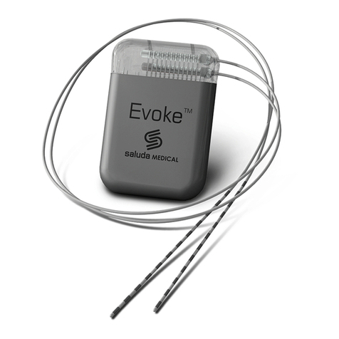
SALUDA MEDICAL Evoke Instructions for use

Document Reference: CLIN-UMAN-002424 Revision: 12.00
Evoke™ SCS System Clinical Manual
Use of the Evoke Clinical Interface (CI) and software (CPA) with the
Evoke Clinical System Transceiver (CST) for programming the Evoke
SCS System

Evoke™ Clinical Manual
Document Reference: CLIN-UMAN-002424 Revision: 12.00 Page 2 of 56
Table of Contents
1DESCRIPTION .............................................................................................................. 4
1.1 THE CONCEPT OF FEEDBACK CONTROL (FC)......................................................................... 4
1.2 EVOKE CLOSED LOOP STIMULATOR (CLS) ........................................................................... 4
1.3 EVOKE EXTERNAL CLOSED LOOP STIMULATOR (ECLS)............................................................ 4
1.4 EVOKE 12C PERCUTANEOUS LEAD KIT,60CM AND 90CM ...................................................... 5
1.5 EVOKE 12C LEAD EXTENSION KIT,55CM ............................................................................ 5
1.6 EVOKE LEAD ADAPTER KIT ............................................................................................... 5
1.7 EVOKE POCKET CONSOLE (EPC) ....................................................................................... 5
1.8 EVOKE CHARGER ........................................................................................................... 5
1.9 EVOKE CLINICAL INTERFACE (CI) ....................................................................................... 5
1.10 EVOKE CLINICAL SYSTEM TRANSCEIVER (CST) .................................................................. 5
2PACKAGE CONTENTS................................................................................................... 6
2.1 EVOKE CLINICAL INTERFACE (CI) ....................................................................................... 6
2.2 EVOKE CLINICAL SYSTEM TRANSCEIVER (CST)...................................................................... 6
3INDICATION FOR USE .................................................................................................. 6
4CONTRAINDICATIONS ................................................................................................. 6
5WARNINGS AND PRECAUTIONS .................................................................................. 6
5.1 PRECAUTIONS ............................................................................................................... 6
6INTRODUCTION........................................................................................................... 8
6.1 EVOKE CLINICAL INTERFACE (CI) ....................................................................................... 8
6.2 EVOKE CLINICAL SYSTEM TRANSCEIVER (CST)...................................................................... 9
7CLINICAL INTERFACE – GENERAL PROGRAMMING USING THE CPA ............................. 9
7.1 CONNECTING THE CI TO THE CST AND ECLS/CLS................................................................. 9
7.2 SET STIMULATOR TIME .................................................................................................. 12
7.3 RETRIEVE OR SET THE PATIENT ID AND PATIENT ZONE.......................................................... 13
7.4 MEASURE ELECTRODE IMPEDANCE................................................................................... 14
7.5 SET UP LEAD ORIENTATION ............................................................................................. 15
7.6 PROGRAMMING OVERVIEW............................................................................................ 16
7.7 CHOOSE THE STIMULATION ELECTRODES AUTOMATICALLY ..................................................... 16
7.8 START AND STOP STIMULATION ....................................................................................... 17
7.9 SET UP ECAP MEASUREMENT......................................................................................... 19
7.10 SET UP FEEDBACK CONTROL (FC) THERAPY .................................................................... 20
7.11 ENABLE FEEDBACK CONTROL ...................................................................................... 21
7.12 SAVE A PROGRAM TO THE STIMULATOR......................................................................... 21
7.13 INTERLEAVED STIMULATION........................................................................................ 24
8CLINICAL INTERFACE – SETTINGS GUIDE.................................................................... 27
8.1 STIMULATION SETTINGS MENU....................................................................................... 27
8.2 MEASUREMENT AND FEEDBACK SETTINGS MENU ............................................................... 27
8.3 ELECTRODE SELECTION MODES ........................................................................................ 28
8.4 CURRENT STEERING ...................................................................................................... 28
8.5 PATIENT PERCEPTION.................................................................................................... 29
8.6 PATIENT SURVEY ......................................................................................................... 30
8.7 CLS MENU................................................................................................................. 31
8.8 NAVIGATION MENU ..................................................................................................... 33
8.9 SETTINGS MENU.......................................................................................................... 33
8.10 ALERT AND ERROR DISPLAY......................................................................................... 34
9INTRA-OPERATIVE PROGRAMMING WITH THE CI ..................................................... 35

Evoke™ Clinical Manual
Document Reference: CLIN-UMAN-002424 Revision: 12.00 Page 3 of 56
9.1 CONFIRMATION OF OPTIMAL LEAD PLACEMENT................................................................... 36
9.2 CONFIRMATION OF PROPER CLS CONNECTION.................................................................... 37
10 POST-OPERATIVE PROGRAMMING PROCEDURES ..................................................... 38
10.1 CONNECTING THE LEAD OR LEAD EXTENSION TO THE LEAD ADAPTER ..................................... 38
10.2 CONNECT THE LEAD ADAPTER CABLE TO THE LEAD ADAPTER EXTENSION ................................ 41
11 OPERATION OF STIMULATOR WHEN ERRORS OCCUR ............................................... 42
11.1 OUT OF COMPLIANCE................................................................................................ 42
11.2 REFERENCE CLOCK ERROR .......................................................................................... 42
11.3 ELECTRODE DISCONNECTED ........................................................................................ 42
11.4 CURRENT AT MAXIMUM ............................................................................................ 42
11.5 ERT CLIPPING ......................................................................................................... 42
12 EVOKE POCKET CONSOLE AND EVOKE CHARGER....................................................... 43
12.1 PAIR EPC TO STIMULATOR ......................................................................................... 43
12.2 EVOKE CHARGER ...................................................................................................... 43
13 PATIENT EDUCATION AND ID CARD .......................................................................... 44
14 MAINTENANCE OF THE EVOKE CI AND EVOKE CST .................................................... 44
14.1 MAINTENANCE OF THE EVOKE CI................................................................................. 44
14.2 MAINTENANCE OF THE EVOKE CST .............................................................................. 44
15 DISPOSAL OF DEVICES............................................................................................... 44
16 TROUBLESHOOTING.................................................................................................. 45
17 TECHNICAL SPECIFICATIONS...................................................................................... 48
17.1 DEVICE SPECIFICATIONS ............................................................................................. 48
17.2 WIRELESS COMMUNICATION ...................................................................................... 49
17.3 ELECTROMAGNETIC INTERFERENCE............................................................................... 50
18 GLOSSARY AND SYMBOLS......................................................................................... 53
18.1 GLOSSARY .............................................................................................................. 53
18.2 SYMBOLS................................................................................................................ 54
19 REGULATORY STATEMENTS ...................................................................................... 55
20 CONTACT US ............................................................................................................. 56
Trademarks
Saluda, Evoke, and the Saluda Medical logo are either trademarks or registered trademarks
of Saluda Medical Pty Ltd.
Copyright © 2019 Saluda Medical Pty Ltd, Sydney, Australia. All rights reserved.
Refer to the Evoke SCS System Surgical Guide for:
•Instruction on the implantation of the Evoke System components
•System warnings and precautions
•Other system component device specifications and package contents
Refer to the Evoke SCS System User Manual for full details on the use of the
Evoke Pocket Console (EPC) and Evoke Charger.
Refer to the Evoke SCS System MRI Guidelines for information on the safe
use of the Evoke System in the MRI environment.
Manuals are accessible at http://www.saludamedical.com/manuals.

Evoke™ Clinical Manual
Document Reference: CLIN-UMAN-002424 Revision: 12.00 Page 4 of 56
1Description
The Saluda™ Medical Evoke™ SCS System is a Spinal Cord Stimulation (SCS) system that
comprises several components to deliver therapy for the management of chronic,
intractable pain. The Evoke Clinical Interface (CI) and Evoke Clinical System Transceiver (CST)
enable the programming of the implantable Closed Loop Stimulator (CLS) and the non-
implantable External Closed Loop Stimulator (eCLS), to deliver therapeutic SCS utilising
Feedback Control (FC).
1.1 The concept of Feedback Control (FC)
Figure 1.1, below, explains the concept of FC in the Evoke SCS System using the
measurement of Evoked Compound Action Potentials (ECAPs). Following a stimulation
impulse, the magnitude of the ECAP generated in the spinal cord from that stimulus is
recorded. This recorded value is compared to the desired target or set point and then used
to automatically adjust the stimulation output of the next stimulus to maintain a constant
evoked stimulation strength.
Figure 1.1: Feedback Control (FC) using ECAP Measurement.
1.2 Evoke Closed Loop Stimulator (CLS)
Ref No. 1002
The Evoke Closed Loop Stimulator (CLS) is a totally implanted spinal cord stimulator that
connects to the 12C Percutaneous Leads and is implanted under the skin for long-term
therapy. The CLS delivers stimulation through the leads and measures the neural response
to stimulation.
1.3 Evoke External Closed Loop Stimulator (eCLS)
Ref No. 1020
During the trial stimulation period, the 12C Percutaneous Leads are connected to the Evoke
External Closed Loop Stimulator (eCLS). The eCLS is an external stimulator used during the
trial stimulation period. The eCLS delivers stimulation through the leads, and measures the
neural response to stimulation.

Evoke™ Clinical Manual
Document Reference: CLIN-UMAN-002424 Revision: 12.00 Page 5 of 56
1.4 Evoke 12C Percutaneous Lead Kit, 60cm and 90cm
Ref No. 1008/1016/1009/1017
The Evoke 12C Percutaneous Leads are placed in the epidural space overlying the spinal
cord, and are connected to an eCLS for a trial stimulation period, or to a CLS for long-term
therapy. One or two leads, each with 12 electrodes, are implanted.
1.5 Evoke 12C Lead Extension Kit, 55cm
Ref No. 1011
The Evoke 12C Lead Extensions are required when the implanted lead does not reach the
CLS pocket, or when trialling a permanently implanted lead, when an extension is
externalised for connection to an eCLS. They may be used optionally in other circumstances.
1.6 Evoke Lead Adapter Kit
Ref No. 1028
The Evoke Lead Adapter, Lead Adapter Cable, and Lead Adapter Extension allow you to
connect the eCLS to the implanted leads for intraoperative testing and trial stimulation.
1.7 Evoke Pocket Console (EPC)
Ref No.1003
The Evoke Pocket Console (EPC) allows the patient to control their therapy and actively
monitors the stimulator battery status and other elements of the system. The EPC and the
stimulator communicate with each other wirelessly.
1.8 Evoke Charger
Ref No.1006 - EU/4006 - UK/5006 - AU
The Evoke Charger allows you to recharge the battery in a CLS (or eCLS, if applicable). The
Charger coil (attached to the Charger) is placed over the CLS and charge is transferred to the
CLS through thin clothing and the skin. The Charger kit also includes a power adapter for
recharging the Charger.
1.9 Evoke Clinical Interface (CI)
Ref No. 1024
The Evoke Clinical Interface (CI) is a tablet computer with a preinstalled programming
application (the Clinical Programming Application (CPA)) used by the clinician to adjust the
therapy settings of the Evoke CLS and eCLS.
1.10 Evoke Clinical System Transceiver (CST)
Ref No. 1004
The Evoke Clinical System Transceiver (CST) is a plug in device (USB connection) that enables
exchange of information wirelessly between the CI and the stimulator.

Evoke™ Clinical Manual
Document Reference: CLIN-UMAN-002424 Revision: 12.00 Page 6 of 56
2Package contents
2.1 Evoke Clinical Interface (CI)
Contents: One (1) Tablet Computer (Microsoft provided)
One (1) Tablet Keyboard (Microsoft provided)
One (1) Tablet Pen (Microsoft provided)
Four (4) Power Cables for EU/UK&IRE/AUS/US (Saluda provided)
One (1) Quick Start Guide (Microsoft provided)
One (1) Set of Safety and Warranty Documents (Microsoft provided)
2.2 Evoke Clinical System Transceiver (CST)
Contents: One (1) Clinical System Transceiver (CST)
3Indication for use
The Saluda Medical Evoke SCS System is indicated as an aid in the management of chronic
intractable pain of the trunk and/or limbs.
4Contraindications
The Evoke System should not be used in patients who:
•Are unable to operate the system.
•Are unsuitable surgical candidates.
•Are unsuitable candidates for SCS.
5Warnings and Precautions
Note: For general system warnings and precautions refer to the Evoke SCS System Surgical
Guide, accessible at http://www.saludamedical.com/manuals.
Note: The Evoke CI is based on a Microsoft Surface Pro tablet computer. Non-therapy
specific warnings and precautions on this product can be found at
https://support.microsoft.com/en-gb/help/4023454/safety-information.
5.1 Precautions
5.1.1 Unsupported software applications
Do not load software applications onto the Evoke CI. The Evoke CI has all the necessary
software required to interact with and program the Evoke SCS System from Saluda Medical.
Other applications could interfere in unpredictable ways with the programming software
installed and affect the delivery of therapy for patients. Any required software installations
shall be supported directly by Saluda Medical representatives or via detailed instructions
concerning specific installations as required.

Evoke™ Clinical Manual
Document Reference: CLIN-UMAN-002424 Revision: 12.00 Page 7 of 56
5.1.2 Unsupported hardware
Do not connect any device to the Evoke CI other than the supplied: keyboard, charger
and Evoke CST. Do not connect the Evoke CST to any device other than a Saluda Medical
supplied Evoke CI. Unsupported hardware could interfere in unpredictable ways with the
programming software installed and affect the delivery of therapy for patients.
For data file extraction, it is permissible to use an external USB memory stick that has
passed a screening check by an up-to-date anti-virus software application, but no files
should be transferred onto the CI unless otherwise instructed by Saluda Medical to do so.
5.1.3 Shared IT networks
Network connection (via Wi-Fi) is only permitted to secure networks. Connecting to
unsecure networks could lead to the modification of the CI system or software that interfere
in unpredictable ways with the programming software installed and affect the delivery of
therapy for patients.
5.1.4 Modification of the programming software
Do not attempt to modify the Clinical Programming Application (CPA) software which
comes preinstalled on the CI for the programming of Saluda Medical neurostimulators. Any
deletion or modification of files associated with the CPA could adversely affect the
system's ability to effectively adjust therapy for patients.
Required software upgrades will be supported directly by Saluda Medical representatives or
via detailed instructions concerning specific upgrades as required. Additionally, any
stimulator software upgrades will be fully supported by Saluda Medical representatives –do
not attempt to modify the stimulator software without Saluda Medical’s instruction.
5.1.5 Non-sterile components
DO NOT STERILISE either the CI or CST; these items are not to be sterilised and doing so
could irrevocably damage the devices.
5.1.6 Clinical staff training
Clinical staff using the CI/CST to program the Evoke SCS System must be adequately
trained in the programming of SCS systems generally. Additionally, clinical staff
programming the Evoke SCS System should have read the instructions within this manual. A
poor understanding of the programming of SCS systems generally, and the Evoke system
specifically, could cause unpleasant or painful stimuli for patients.
5.1.7 Electromagnetic interference (EMI)
As the CI communicates via the CST to the neurostimulator (eCLS or CLS) wirelessly, the
quality of this connection can be adversely affected by some types of electrical equipment

Evoke™ Clinical Manual
Document Reference: CLIN-UMAN-002424 Revision: 12.00 Page 8 of 56
that generate EMI. Such equipment should be avoided where possible when programming
and/or suspected if communication between stimulator and CI/CST is poor. Examples of
such equipment found in clinical environments include but are not limited to: Mobile
phones, electro-surgery tools, electromagnets, radiofrequency identification devices and
emergency vehicle/services radios.
5.1.8 General precautions for the CI
The CI is a critical piece of equipment to enable the delivery of therapy. Always handle it
with care and regularly inspect the device for damage and/or impaired functioning. Never
modify the CI in any way. If you have concerns about the integrity of the CI/CST, contact
Saluda Medical representatives to arrange repair or replacement. The CI runs on a
rechargeable battery and can be used wirelessly or whilst plugged in via the power adapter
supplied. Care should be taken to keep the CI well charged so it can be used in clinical
environments where plug sockets are not readily available. Always have a spare charged CI
available in case of malfunction.
6Introduction
6.1 Evoke Clinical Interface (CI)
The CI is a Microsoft Surface Pro tablet computer. Figure 6.1 shows the basic physical
specifications. Full specifications for the tablet computer are available at
https://support.microsoft.com/en-gb/hub/4295210/surface-pro-help. The computer is not
physically modified in any way. The CI operates on the Microsoft Windows platform. The CI
is supplied with the software necessary for programming Saluda Medical stimulators pre-
installed, and no other software should be installed on the device.

Evoke™ Clinical Manual
Document Reference: CLIN-UMAN-002424 Revision: 12.00 Page 9 of 56
Figure 6.1: Basic Physical Properties of CI.
Upon starting and logging in to the CI, the user will immediately find a program icon .
This will lead the user into the Clinical Programming Application (CPA) that enables
programming of either the Evoke eCLS or CLS.
Note: Login password for the CI will be provided by Saluda Medical representatives and
cannot be changed. All potential CI operators should be made aware of this password.
6.2 Evoke Clinical System Transceiver (CST)
The CST is a radio telemetry device that enables communication between the CI and the
stimulator (eCLS or CLS). Commands generated through the CPA loaded on the CI are sent to
the stimulator and data is received back from the stimulator to display in the CPA via the
CST. The CST is connected to the CI via a USB connector and receives power from the CI via
this link.
7Clinical Interface – General programming using the CPA
7.1 Connecting the CI to the CST and eCLS/CLS
To program and download data from the eCLS or CLS, communication must first be
established. The CST connects to the CI to communicate using a radio signal transmitted to
the eCLS or CLS.
1. Connect the CST to the CI with the USB connection. See Figure 7.1.
On/Off Button
Touchscreen
Charging Port
Keyboard

Evoke™ Clinical Manual
Document Reference: CLIN-UMAN-002424 Revision: 12.00 Page 10 of 56
Figure 7.1: Connecting the CST to the CI.
2. Position the CST near the stimulator and double-click the Evoke Clinical Programing
Application (CPA) icon to start the CPA (see Figure 7.2 for the main screen
layout).
Note: The CST can link with the stimulator within a 1.0 m (3.3 ft) radius.
Note: EMI can affect the quality of this wireless link; see Section 5.1.7 - Electromagnetic
interference (EMI).

Evoke™ Clinical Manual
Document Reference: CLIN-UMAN-002424 Revision: 12.00 Page 11 of 56
Figure 7.2: Functional layout of the CPA main screen.
Stimulation Settings
(hidden)
ECAP Measurement bar
Side
Bar
Electrode Display Window
(‘Stimulation Settings’ and ‘ECAP
Measurement Settings’ hidden)
Stimulation
Amplitude Control
ECAP Measurement and
Current rolling plot
Text
Input
Error Log
Count
Stimulation sets
Patient
ID/Patient
zone
ECAP Measurement
Settings (hidden)
Stored
programs
ECAP
Display
Electrode Selection
Mode
CLS Menu and RF
communication
Active
program
Navigation Menu

Evoke™ Clinical Manual
Document Reference: CLIN-UMAN-002424 Revision: 12.00 Page 12 of 56
3. Choose the appropriate Visit Name from the dropdown menu (see Figure 7.3).
4. Touch Connect to Implant to search for nearby stimulators (see Figure 7.3).
Figure 7.3: Location of the Visit Name dropdown menu and Connect to Implant button
5. Click on the stimulator serial number that you wish to connect to.
6. The CPA will connect to the stimulator and retrieve any patient data and Programs.
Note: Depending on the amount of data saved on the device this could take several
minutes. Downloading can be cancelled but this is not recommended as any system
error and device usage logs will be missed.
7. The CPA will display the electrode display window when it has successfully
connected and downloaded data from the stimulator.
Note: When the CPA connects to a stimulator it will attempt to download three log
files from the stimulator. If any logs cannot be downloaded an error message will be
displayed on the ECAP Measurement and Current rolling plot (see Section 8.10). To
download the logs manually, such as when download fails, refer to Section 8.7.
7.2 Set stimulator time
1. Touch the CLS icon to open the CLS Menu.
2. Touch Sync Time in the CLS Menu to set the stimulator time to the CI time (if the
time is not already synchronized).
Note:The time error between the CI and stimulator is displayed in brackets.
Visit Name
dropdown menu
Connect to
Implant button

Evoke™ Clinical Manual
Document Reference: CLIN-UMAN-002424 Revision: 12.00 Page 13 of 56
Note:If out of sync, a red ‘clock’ icon will be displayed in the CLS icon window
and the time error between CI and stimulator is displayed in brackets in the
CLS menu.
Note:Ensure that the time and date on the CI are correct (top left corner of CPA
screen, Figure 7.2). Refer to the CI instructions (see Section 6.1 for link) to change
the time and date.
7.3 Retrieve or set the Patient ID and Patient Zone
7.3.1 For an existing patient
1. On connection to the stimulator the Patient ID and Patient Zone are retrieved and
displayed under the CLS icon (see Figure 7.4).
Figure 7.4: CLS Icon with Patient ID and Zone underneath.
2. Check that the correct Patient ID and Patient Zone have been retrieved.
7.3.2 For a new patient
1. For a new patient, touch the Patient ID box under the CLS icon (see Figure 7.4).
2. Delete any existing text and enter the new Patient ID.
3. Touch the Done button that appears above the ID when you finish typing (see Figure
7.5).
Figure 7.5: CLS Icon with Patient ID and Done button.
Note: If you do not click the Done button, the Patient ID will be automatically
updated in the stimulator when you start stimulation.
4. Navigate to the settings page by opening the Navigation Menu and tapping
Settings (see Figure 7.6). Select the appropriate Patient Zone (see Figure 7.7).
5. Return to the CLS programming page by opening the Navigation Menu and
tapping Programming (see Figure 7.6).
Patient ID
field
Patient
Zone field

Evoke™ Clinical Manual
Document Reference: CLIN-UMAN-002424 Revision: 12.00 Page 14 of 56
Figure 7.6: Navigation Menu
Figure 7.7: Settings Menu with Patient Zone dropdown menu highlighted
7.4 Measure electrode impedance
Measure the electrode impedance to determine if all connections are intact between leads,
any lead adapters, and the stimulator.
1. Touch the Impedance icon .
2. The impedance on the 24 electrodes and CLS case will be shown in the electrode
display window (see Figure 7.8).
Note: The icon will spin during the measurement and stop once it is complete.
Patient Zone
dropdown menu

Evoke™ Clinical Manual
Document Reference: CLIN-UMAN-002424 Revision: 12.00 Page 15 of 56
Figure 7.8: Impedances displayed on the 24 electrodes and CLS case (#25).
3. Electrodes with a cross through them are high impedance (> 4000 Ω) and
may be disconnected. Disconnected electrodes show an impedance of ∞and cannot
be used for stimulation or recording.
Note: The CLS case cannot be used for stimulation, and may show as high impedance
(> 4000 Ω). The CLS case may be used for recording even if high impedance is shown.
4. Electrodes with a lightning bolt through them may be shorted (< 50 Ω) and
care should be taken when programming.
Caution: If the electrodes show an open circuit (disconnected):
•Wipe any blood or fluid off the lead connection contacts.
•If the system is fully implanted, high impedance may indicate that the lead is
broken or dislodged from the header and the patient may require revision
surgery if stimulation is insufficient.
Note: When connected to an eCLS the CLS case is disconnected and cannot be used.
7.5 Set up lead orientation
1. Touch the handle at the bottom of the lead image to move it up, down, or switch
sides to a position that reflects the lead location in the most recent fluoroscopy
image (see Figure 7.9). This will aid in determining the best stimulation and
measurement electrode combination.

Evoke™ Clinical Manual
Document Reference: CLIN-UMAN-002424 Revision: 12.00 Page 16 of 56
Figure 7.9: You can drag the leads up, down or switch sides.
7.6 Programming overview
1. Test stimulation from several electrodes (see Section 7.7 and 7.8) and ask the patient
to report where they feel paresthesia.
2. Determine the stimulation electrodes that give the best paresthesia coverage of the
patient’s painful anatomy.
3. Determine the settings that provide a good measurement of the neural response to
stimulation (ECAP – see Section 7.9).
4. Determine the settings for optimum Feedback Control (FC) therapy (see Section
7.10).
5. Save the Program to the eCLS/CLS memory (see Section 7.12), and proceed to set up
a maximum of four programs.
7.7 Choose the stimulation electrodes automatically
1. Stop stimulation if stimulation is running.
2. Change the Electrode Selection Mode icon (see Figure 7.2) until the Automatic
Electrode Selection icon is displayed.
3. In the electrode display window, touch the electrode that you wish to use as the
stimulation electrode .
4. Touch the stimulation electrode again to cycle through electrode configurations.
Tripolar: 1 lead
Bipolar: 1 lead
Tripolar: 2 leads
Bipolar: 2 leads

Evoke™ Clinical Manual
Document Reference: CLIN-UMAN-002424 Revision: 12.00 Page 17 of 56
5. The CPA will automatically select the stimulation , return ,
measurement and reference electrodes for you.
•You may steer the current between stimulation electrodes (see Section 8.4).
•You can also manually change the electrode configuration (see Section 8.3).
6. Touch Set Defaults icons in the Settings menu, Stimulation Settings menu and ECAP
Measurement Settings menu (see Figure 7.10) to set standard stimulation
parameters.
7. Restart stimulation on the new electrodes.
Note: You cannot change the stimulation or return electrodes while stimulation is
running.
Figure 7.10: Set defaults buttons in the Stimulation Settings, ECAP Measurement
Settings, and Settings menus (shown from left to right respectively).
7.8 Start and stop stimulation
Touch the Stimulation Settings icon to change the stimulation parameters. The icon
will change to show the Electrode Display icon (Figure 7.11). Changes made to the
Stimulation Settings will affect the Stimulation Amplitude Control bar on the right (refer to
Figure 7.12 for more details).

Evoke™ Clinical Manual
Document Reference: CLIN-UMAN-002424 Revision: 12.00 Page 18 of 56
Figure 7.11: Location of the Stimulation Settings Menu
and Start Stimulation arrow on the CPA.
1. Touch the Start Stimulation arrow (see Figure 7.11).
Note: The arrow will change orientation to an Up arrow for increasing
stimulation current, and various areas of the screen will become active, e.g. the
ECAP Measurement and Current rolling plot.
2. Touch the Up arrow to increase stimulation current to the desired level (mA;
see Figure 7.12A).
3. Touch the Down arrow to decrease stimulation current (Figure 7.12G).
Note: The current will increase/decrease by the Current Increment (mA) set. The
increment in the current scale is shown on the right side (Figure 7.12D). The scale
will extend to the Maximum current set (Figure 7.12B).
A: Up arrow
B: Maximum current
C: Current scale
D: Current increment scale
E: Desired current level
F: Current increment
G: Down arrow
Figure 7.12: Features of the Stimulation Amplitude Control.
Start
Stimulation
A
B
E
G
F
D
C

Evoke™ Clinical Manual
Document Reference: CLIN-UMAN-002424 Revision: 12.00 Page 19 of 56
7.8.1 Stop
1. Touch the Stop button to stop stimulation at any time.
7.9 Set up ECAP measurement
The stimulator records the ECAP signal and displays a graph of the ECAP on the
programming screen (Figure 7.13). ECAP measurement is only possible when the stimulation
is running and a clear signal is visible.
Figure 7.13: Location of ECAP display on the CPA.
The ECAP display (Figure 7.14) shows both a single and averaged ECAP, as well as the
correlation filter used to measure the ECAP. The ECAP display shows the current and
recommended measurement settings for the ECAP, the Sampling Period, and buttons to
zoom in and out of the Y-scale.
Figure 7.14: ECAP Display. Note the measurement settings, in order, are: Sampling Delay,
Processing Offset (number of samples), filter frequency, and number of filter samples.
Graph of ECAP
Zoom out
(Y-scale)
Zoom in
(Y-scale)
Sampling
period
Raw ECAP
(orange)
Average
ECAP (black)
Recommended
measurement settings
Measurement settings
in use
Correlation filter used
to measure (white)

Evoke™ Clinical Manual
Document Reference: CLIN-UMAN-002424 Revision: 12.00 Page 20 of 56
Figure 7.15: A) ECAP Measurement and Current rolling plot; B) ECAP Measurement
Settings menu; C) ECAP Measurement settings icon; D) Patient sensitivity graph.
1. Touch the ECAP Measurement Settings icon to open the ‘Measurement and
Feedback Settings’ menu (Figure 7.15B). The icon will change to show the Electrode
Display icon (Figure 7.15C).
2. Start stimulation and increase the stimulation current (see Section 7.8) so that a
clear ECAP signal is visible and/or above the patient’s perception threshold.
3. Touch ‘Apply’ to set the optimal Processing Offset . The
open circle on the graph is the recommended offset (peak of graph), while the black
line is the offset setting in use.
4. Touch ‘Apply’ to set the optimal Filter Frequency . The
open circle on the graph is the recommended frequency (peak of graph), while the
black line is the frequency setting in use.
5. The ECAP Measurement and Current rolling plot (Figure 7.15A) displays the ECAP
measurement (top) and current (bottom) over time.
7.10 Set up Feedback Control (FC) therapy
The settings for FC therapy vary between patients and for different electrode
configurations. Settings can be optimised in the ‘Measurement and Feedback Settings’
menu (Figure 7.15B).
The settings for the FC therapy depend on the sensitivity of the ECAP to changes in current.
The CPA can measure ECAP sensitivity as the current is varied (see Figure 7.15D).
1. Optimise the ECAP measurement (refer to Section 7.9).
2. Increase current from near paresthesia threshold to a strong but comfortable level.
3. The Sensitivity Graph will display the ECAP size data as a function of current (see
Figure 7.16).
B
A
C
D
Other manuals for Evoke
2
Table of contents
Other SALUDA MEDICAL Medical Equipment manuals
Popular Medical Equipment manuals by other brands

Gima
Gima RS01 user manual

Ossur
Ossur Unloader One OTS & Custom Instructions for use

Beka Hospitec
Beka Hospitec NORA Alu user manual

Champion
Champion TMM5 Plus Owner's operating and maintenance manual

Otto Bock
Otto Bock 17KO1 Series Instructions for use

sorin
sorin SYNTHESIS C Ph.I.S.I.O Instructions for use