Saluki S1465 Series User manual

S1465 Series Signal Generator
User Manual
Saluki Technology Inc.

Tel: 886.909 602 109 Email: sales@salukitec.com
www.salukitec.com
2
The manual applies to the signal generators of the following models:
S1465C signal generator, 100kHz - 10GHz
S1465D signal generator, 100kHz - 20GHz
S1465F signal generator, 100kHz - 40GHz
S1465H signal generator, 100kHz - 50GHz
S1465L signal generator, 100kHz - 67GHz
S1465B-V signal generator, 100kHz - 6GHz
S1465C-V signal generator, 100kHz - 10GHz
S1465D-V signal generator, 100kHz - 20GHz
S1465F-V signal generator, 100kHz - 40GHz
S1465H-V signal generator, 100kHz - 50GHz
S1465L-V signal generator, 100kHz - 67GHz
Standard pack and accessories:
Part No.
Name
1
Main machine
2
User manual
3
Power cable assembly
4
Certificate of quality
Options of the S1465(-V) series signal generator in addition to standard accessories:
(1) S1465 series options:
Option ID
Description
Function
Match
S1465-H01A
115dB programmable step
attenuator
To expand output power dynamic
range
For model
S1465C/D/F
S1465-H01B
90dB programmable step
attenuator
To expand output power dynamic
range
For model S1465H/L
S1465-H02A
Analog modulation
Additional analog modulation, including
AM, FM, ΦM, and low-frequency output
All models
S1465-H02B
Pulse modulation
Additional pulse modulation, with the
minimum pulse width of 100ns
All models

Tel: 886.909 602 109 Email: sales@salukitec.com
www.salukitec.com
3
S1465-H02C
Narrow pulse modulation
Additional pulse modulation, with the
minimum pulse width of 20ns
All models, including
H02B
S1465-H03
Analog sweep
Additional analog sweep (slope sweep)
All models
S1465-H04
Ultra low phase noise
To reduce phase noise,
10GHz@10kHz: -120dBc/Hz
All models
S1465-H05
High-power output
To increase the maximum output
power
All models
S1465-H06
Enhanced high-power output
To increase the maximum output
power of 10MHz-20GHz substantially
Only S1465D option
S1465-H80
S87230 USB power probe
For power measurement and
calibration (9kHz-6GHz)
All models
S1465-H81
S87231 USB power probe
For power measurement and
calibration (10MHz-18GHz)
All models
S1465-H82
S87232 USB power probe
For power measurement and
calibration (50MHz-26.5GHz)
All models
S1465-H83
S87233 USB power probe
For power measurement and
calibration (50MHz-40GHz)
All models
S1465-H90
Electromagnetic compatibility
As specified in GJB-151A (touch
screen disabled)
All models
S1465-H91
N RF output port
To change RF output port to N (female)
Only S1465D option
S1465-H92
Rear panel RF output
To move RF output port to rear panel
All models
S1465-H93
Front handle kit
Front panel mounting handle
All models
S1465-H94
Rack installation kit
Kit for installing instrument on the
cabinet
All models
S1465-H95
Commercial calibration certificate
Instrument is entrusted to metrology
service
All models
S1465-H99
Aluminum alloy transport case
For safety transportation
All models
S1465-S10
Complex pulse sequence (software)
Pulse generation mode expansion,
support double pulse, multi-pulse,
re-frequency staggered, re-frequency
jitter, re-frequency slip and other
complex pulse sequence generation
(need option H02B/C)
All models

Tel: 886.909 602 109 Email: sales@salukitec.com
www.salukitec.com
4
(2) S1465-V series options:
Option ID
Description
Function
Match
S1465V-H01A
115dB programmable step
attenuator
To expand output power dynamic
range
For model
S1465C/D/F-V
S1465V-H01B
90dB programmable step attenuator
To expand output power dynamic
range
For model
S1465H/L-V
S1465V-H02A
Analog modulation
Additional analog modulation, including
AM, FM, ΦM, and low-frequency output
All models
S1465V-H02B
Pulse modulation
Additional pulse modulation, with the
minimum pulse width of 100ns
All models
S1465V-H02C
Narrow pulse modulation
Additional pulse modulation, with the
minimum pulse width of 20ns
All models, including
H02B
S1465V-H03
Analog sweep
Additional analog sweep (slope sweep)
All models
S1465V-H04
Ultra low phase noise
To reduce phase noise,
10GHz@10kHz: -120dBc/Hz
All models
S1465V-H05
High-power output
To increase the maximum output
power
All models
S1465V-H31
Large Modulation Bandwidth
Internal demodulation extend to
200MHz
All models
S1465V-H32
Internal Baseband large memory
Extend to 8GB
S1465V-H33
Broadband External IQ Input
Add wideband external IQ input
function.
For model
S1465C/D/F-V
S1465V-H35
High-speed External Baseband
Data Input (Optical Port)
Support user external arbitrary wave
baseband data to be imported in real
time through the optical fiber interface,
a total of 4 optical fiber interfaces.
All models
S1465V-H36
500MHz Large Modulation
Bandwidth
The internal modulation bandwidth is
expanded to 500MHz.
All models
S1465V-H37
1GHz Large Modulation
Bandwidth
The internal modulation bandwidth is
expanded to 1GHz.
All models
S1465V-H80
S87230 USB power probe
For power measurement and
calibration (9kHz-6GHz)
All models
S1465V-H81
S87231 USB power probe
For power measurement and
calibration (10MHz-18GHz)
All models

Tel: 886.909 602 109 Email: sales@salukitec.com
www.salukitec.com
5
S1465V-H82
S87232 USB power probe
For power measurement and
calibration (50MHz-26.5GHz)
All models
S1465V-H83
S87233 USB power probe
For power measurement and
calibration (50MHz-40GHz)
All models
S1465V-H90
Electromagnetic compatibility
As specified in GJB-151A (touch
screen disabled)
All models
S1465V-H91
N RF output port
To change RF output port to N (female)
Only S1465D-V option
S1465V-H92
Rear panel RF output
To move RF output port to rear panel
All models
S1465V-H93
Front handle kit
Front panel mounting handle
All models
S1465V-H94
Rack installation kit
Kit for installing instrument on the
cabinet
All models
S1465V-H95
Commercial calibration certificate
Instrument is entrusted to metrology
service
All models
S1465V-H99
Aluminum alloy transport case
For safety transportation
All models
S1465V-S01
Arbitrary Wave
Support arbitrary wave data download
and play, generate baseband signal or
realize signal playback.
All models
S1465V-S02
Linear Frequency Modulation
Support intra-pulse linear frequency
modulation function.
All models
S1465V-S03
Gaussian White Noise
Support pure noise generation, additive
noise and continuous wave
interference functions.
All models
S1465V-S04
Dynamic Fading Function
Support general fading simulation and
dynamic fading simulation of aviation
channel. Need option S01.
All models
S1465V-S05
Radar Signal Simulation
Can simulate radar radiation signals,
echo signals, clutter signals and
various deceptive and suppressive
interferences of various systems, and
has a hierarchical multi-radar
simulation scene management
function. Need option S01.
All models
S1465V-S10
Complex Pulse Sequence
The pulse generation pattern is
extended to support complex pulse
sequences such as double pulse,
All models

Tel: 886.909 602 109 Email: sales@salukitec.com
www.salukitec.com
7
Preface
Thanks for choosing S1465 Series Signal Generator produced by Saluki Technology Inc. Please read this user manual
carefully for your convenience.
We devote ourselves to meeting your demands, providing you high-quality measuring instrument and the best
after-sales service. We persist with “superior quality and considerate service”, and are committed to offering satisfactory
products and service for our clients.
Manual No.
S1465-03-01
Version
Rev01 2019.04
Saluki Technology
Manual Authorization
The information contained in this User Manual is subject to change without notice. The power to interpret the contents
of and terms used in this Manual rests with Saluki.
Saluki Tech owns the copyright of this User Manual which should not be modified or tampered by any organization or
individual, or reproduced or transmitted for the purpose of making profit without its prior permission, otherwise Saluki
will reserve the right to investigate and affix legal liability of infringement.
Product Quality Certificate
The product meets the indicator requirements of the manual at the time of delivery. Calibration and measurement are
completed by the measuring organization with qualifications specified by the state, and relevant data are provided for
reference.
Quality/Environment Management
Research, development, manufacturing and testing of the product comply with the requirements of the quality and
environmental management system.
Contacts
Service Tel:
886.909 602 109
Website:
www.salukitec.com
Email:
sales@salukitec.com
Address:
No. 367 Fuxing N Road, Taipei 105, Taiwan (R.O.C.)

Tel: 886.909 602 109 Email: sales@salukitec.com
www.salukitec.com
8
Content
1 Overview.................................................................................................................................................................. 9
1.1 General.......................................................................................................................................................... 9
1.2 Safety guide..................................................................................................................................................16
2 Start Guide............................................................................................................................................................. 21
2.1 Preparation before use................................................................................................................................21
2.2 Description of front and rear panels..............................................................................................................36
2.3 Basic configuration method......................................................................................................................... 40
2.4 Data management...................................................................................................................................... 62
3 Operation Guides................................................................................................................................................... 68
3.1 Basic operation guides................................................................................................................................68
3.2 Advanced operation guides......................................................................................................................... 75
4 Menu...................................................................................................................................................................... 97
4.1 Menu structure and parameter settings.........................................................................................................98
4.2 Menu description...................................................................................................................................... 122
5 Remote Control.................................................................................................................................................... 176
5.1 Remote control Basis................................................................................................................................176
5.2 Remote interface and its configuration........................................................................................................189
5.3 Basic programming method of the VISA interface........................................................................................ 191
5.4 I/O library.................................................................................................................................................195
6 Fault Diagnosis & Repair...................................................................................................................................... 197
6.1 Operating principle....................................................................................................................................197
6.2 Fault diagnosis and troubleshooting........................................................................................................... 198
6.3 Error information.......................................................................................................................................203
6.4 Repair methods........................................................................................................................................ 204
7 Test Methods......................................................................................................................................................... 206
Appendix A Explanations of Terms............................................................................................................................. 218
Appendix B Lookup Table of SCPIs............................................................................................................................ 226
Appendix C Lookup Table of Error Information.............................................................................................................242
Appendix D Lookup Table of PC Keyboard in Function Configuration Windows.............................................................. 243

Tel: 886.909 602 109 Email: sales@salukitec.com
www.salukitec.com
9
1 Overview
This chapter introduces the product features, main scope of application and specifications. Also, it
describes how to properly operate the instrument and electrical safety precautions.
1.1 General
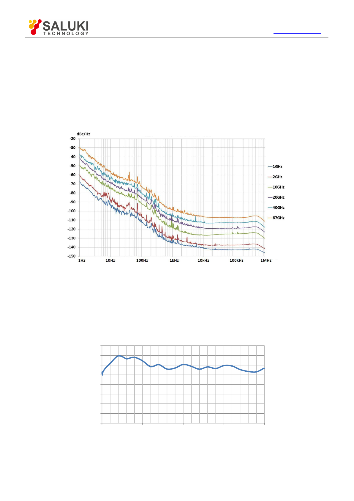
The S1465 series signal generator has a frequency range of 100kHz - 67GHz, excellent
spectrum purity and output power, with SSB phase noise of 10GHz carrier @ 10kHz frequency offset
of - 126dBc/Hz, max. output power up to 1W@20GHz, power dynamic range greater than 150dB
which can meet high demands for test signals; it also features high-precision analog sweep function,
excellent simulation modulation, pulse modulation and vector modulation; the baseband signal
generator is easily set up and flexible, and supports multiple modulation formats, alllowing users to
edit and download the required waveform for signal simulation based on individual needs; the internal
and external vectors have wide modulation bandwidth (internal 200MHz and external 2GHz) which
can meet the needs of broadband signal simulation; the internal modulation signal generator has
frequency up to 10MHz and multiple signal waveforms, pulse modulation supports minimum PW of
20ns and generates flexible pulse trains that can satisfy the needs for testing various complex signals;
the product has a 10.1″ large display with resolution of 1280×800 and can be operated by keys, a
mouse or screen touch, improving the operating experience while enhancing the testing efficiency.
The S1465 series generates high-quality signals in both continuous wave and modulation, making it
an ideal local oscillator and clock source, and a high-performance simulation signal source. It is
mainly used for comprehensive assessment of radar performance, high-performance receiver testing
and component parameter testing, applicable for many fields such as aerospace, radar,
communication, navigation equipment, etc.
1.1.1 Product features
1.1.1.1 Basic function
The S1465 series signal generator developed by Saluki embraces the following main features:
1) Three basic modes of signal output: Continuous wave (CW) signal, sweep signal and digital
modulation signal.
Continuous wave (CW) signal
In this mode, the instrument generates a CW sine signal with the frequency and power level defined
by the user.
Sweep signal
Basic sweep outputs are provided, including step sweep, list sweep and ramp sweep. Multiple sweep
triggering inputs and outputs are provided.
High-precision broadband vector modulation signal output
If an internal baseband is used in the S1465-V signal generator, vector modulation signals of
bandwidth up to 200MHz can be generated; when an external I/Q is used, the modulation bandwidth
is 200MHz, supporting broadband I/Q input of external arbitrary waveform generator, with RF
modulation bandwidth up to 2GHz.
2) Generation of internal broadband and multi-system baseband signals. The vector signal
generator can produce digital modulation (real-time) baseband signals, with single-channel
bandwidth up to 100MHz.
3) External reference clock (ERCLK) input of baseband, and synchronous input of external data
source.
4) Storage and calling of instrument set state, and one-button self test.

Tel: 886.909 602 109 Email: sales@salukitec.com
www.salukitec.com
10
SSB Phase Noise Option H04
Frequency offset
5) Including GPIB, LAN, and other I/O remote interfaces;
1.1.1.2 High performance
1) Excellent spectrum purity
The S1465 series signal generator can generate high-purity signal spectrum, of SSB phase
noise 10GHz carrier@10kHz frequency offset (typical value) -126dBc/Hz, 1GHz carrier@10kHz
frequency offset (typical value) -142dBc/Hz, making it applicable for testing of Doppler radar,
high-performance receiver blocking and adjacent channel selectivity, and an ideal alternative of local
oscillator and low-jitter clock.
Fig. 1.1 SSB Phase Noise
2) Broadband high power output
Typical value of max. output power of H05 high power option: +22dBm @ 20GHz, +20dBm @
40GHz (-V series: +16dBm), +10dBm @ 67GHz (-V series: +6dBm). H06 enhanced high power
option has output power up to 30dBm (1W). During testing, high power excitation signals, if required,
can be obtained without connecting to an external amplifier, and the power has higher accuracy and
stability.
S1465D Max. Output Power (Option H06)
0 5 10 15 20
Frequency/GHz
Fig. 1.2 Max. Output Power of S1465D+H06
Power/dBm

Tel: 886.909 602 109 Email: sales@salukitec.com
www.salukitec.com
11
0 5 10 15 20 25 30 35 40
Frequency /GHz
Fig. 1.3 Max. Output Power of S1465F+H05
S1465F-V Max . Output Power(Option H05)
0 5 10 15 20 25 30 35 40 45
frequency/GHz
Fig. 1.4 Max. Output Power of S1465F-V+H05
3) High-vector modulation bandwidth
The S1465-V series can generate vector signals of modulation bandwidth 200MHz and 2GHz
external (> 3.2GHz carrier).
Fig. 1.5 5GHz Carrier 200MHz Modulation Bandwidth Multi-tone Signal
S1465F Max. Output Power (Option
H05)
Power/dB m
Power/dB m

Tel: 886.909 602 109 Email: sales@salukitec.com
www.salukitec.com
12
Frequency (GHz)
Fig. 1.6 60GHz Carrier 200MHz Modulation Bandwidth Multi-tone Signal
4) Download of high-compatibility arbitrary waveform data format
The S1465-V series supports downloading and playing of arbitrary waveform data in storage
formats of Mat-File 5, ASCII, Binary, cap, csv and up to the depth of 2G sampling point.
Fig. 1.7 Downloading and Playing of Arbitrary Waveform Data
5) Vector modulation accuracy
The S1465-V series has high vector modulation accuracy of EVM<1.4% (test value<1.0% for 100kHz
- 40GHz) and EVM<2.5% (test value<1.5% for 40GHz - 67GHz).
Fig. 1.8 Vector Modulation Accuracy
6) Universal digital modulation in complete formats
The S1465-V series supports real-time generation of universal digital modulation signals in more
than 20 formats including PSK, QAM, FSK, MSK, etc.

Tel: 886.909 602 109 Email: sales@salukitec.com
www.salukitec.com
13
Fig. 1.9 8PSL Fig. 1.10 512QAM
7) Complete series of frequency band
Based on specific demands of different users, the S1465 series signal generator can provide
various test plans for upper frequency limits of 3GHz/6GHz/10GHz/20GHz/40GHz/50GHz/67GHz,
and there are signal generators of common type and with vector modulation function (-V series) for
each frequency band, i.e. totally 14 types of this series. Each type has many options for function and
performance extensions. From measuring-level solutions to basic types, whether you only need test
signals of RF band or of MMW frequency, we guarantee a suitable one for you.
1.1.1.3 Flexibility
1) Large-screen TFT LED gives graphical display and supports operation by screen touch
and front-panel keys.
The S1465 series signal generator is applied with self-designed software, a large screen and a
Chinese/English operation interface to provide a panoramic view of current status information. The
interface is of a window-type operation structure, allowing easy operation by keys and screen touch
for efficient, flexible and convenient use.
Fig. 1.11(a) Screenshot of Actual Operation Interface

Tel: 886.909 602 109 Email: sales@salukitec.com
www.salukitec.com
14
Fig. 1.11(b) Screenshot of Actual Operation Interface
2) It supports flexible function configurations such as sweep, real-time baseband, etc.
The S1465 series signal generator supports flexible configurations such as sweep, real-time
baseband, and trigger source. The setting of trigger source determines the source of the event
triggered, and the setting of trigger mode determines the trigger action after event generation.
Through the combination of both, users can generate trigger signals according to actual needs of the
test.
Fig. 1.12 Baseband Gating (Low Effective)
3) Abundant remote interfaces
There are multiple remote interfaces available for the S1465 series signal generator, including
source module port, GPIB port, network port, for easy remote control and network upgrading.

Tel: 886.909 602 109 Email: sales@salukitec.com
www.salukitec.com
15
Fig. 1.13 Remote interfaces
1.1.2 Typical Applications
1) Building a solid basis for high-reliability satellite communication equipment testing
The S1465-V series can generate high-quality user-defined and basic digital modulation signals
within the frequency range of 100kHz ~ 67GHz, and provide repeatable and reliable tests for satellite
communication system. The high-bandwidth external vector modulation, self-defined data source and
additive noise functions enable users to produce true test signals for product tests.
2) Providing radar equipment and electronic countermeasures system with test signals
for different application scenarios.
The S1465-V series has wide frequency range, high resolution (16bit) and excellent signal
simulation. In combination with synchronous trigger port with rich functions, it produces complex
sequences in various modulation formats by editing waveform segments for different scenarios, in
order to simulate complex interference signals in real combat environment to test the radar ECCM
performance.
3) Providing accurate arbitrary waveform modulation signals for invisible aircraft systems,
high-capacity communication equipment systems and electronic warfare systems (EWS)
to meet the current and future market demands.
The S1465-V series has waveform storage up to 2G sampling point to allow designers to obtain
long-time test scheme closer to reality. It supports five arbitrary waveform data formats that meet the
design requirements of main tool software.
4) High-performance receiver test
With ultra-low SSB phase noise and excellent anharmonic suppression, the S1465 series signal
generator can produce ideal pure signals for testing the phase noise, blocking, adjacent channel
selectivity of high-performance receivers used in radars, electronic wars and communication
equipment.
Fig. 1.14 Application of S1465 series signal generator in High-performance Receiver Test
Source module port

Tel: 886.909 602 109 Email: sales@salukitec.com
www.salukitec.com
16
5) High power device test
The S1465-D series has output power up to 1W to allow high power devices to be tested without
connecting to an external amplifier. Also, it overcomes the test system loss and provides higher
signal power accuracy and stability.
6) Excitation signal and local oscillator substitution
The S1465 series signal generator has extremely pure signal quality and high output power,
making it suitable for signal excitation of various amplifiers and an ideal substitution as a local
oscillator for the one in devices under test such as the transmitter, receiver, etc.
Fig. 1.15 Application of S1465 series signal generator in Local Oscillator Substitution
1.2 Safety guide
Please carefully read and strictly follow the precautions below!
We will spare no effort to ensure that all production processes meet the latest safety standards
and provide users with the highest security. Our product and its auxiliary equipment have been
designed and tested in accordance with relevant safety standards, and a quality assurance system
has been established for product quality monitoring to ensure that the product complies with these
standards. To keep the equipment in good condition and ensure safe operation, please observe the
precautions in this manual. In case of any doubt, please contact us for consultation.
In addition, it is your responsibility to use this product properly. Please carefully read and follow
safety instructions prior to use. This product is applicable to measurement in industrial and laboratory
environments or on the site. Always remember to use this product within its restricted conditions to
avoid personal injury or property damage. Any problems caused by failure to use this product
properly or as required are to be accounted by yourself, and we will not bear any responsibility
therefrom. Therefore, please always follow the safety instructions to prevent any risks of
personal injury or property damage. Please keep the basic safety instructions and product
document properly and deliver them to the end user.
1.2.1 Safety signs
1.2.1.1 Safety signs on the product
The warning signs on the product are given as follows (see Table 1.1):

Tel: 886.909 602 109 Email: sales@salukitec.com
www.salukitec.com
17
Table 1.1 Safety Signs on the Product
Symbol
Meaning
Symbol
Meaning
CAUTION, which indicates
information that requires special
attention from the user, or operation
information or instructions require
attention from the user.
Power ON/OFF
ATTENTION, which represents
handling of heavy equipment.
Readiness Indicator
DANGER! Risk of electric shock.
Direct current (DC)
WARNING! Risk of scalding.
Alternating current (AC)
Protection of conductive terminal
Direct/alternating current (DC/AC)
Ground
Reinforced insulation protection of
instrument
Grounding terminal
EU mark of battery
For detailed description, please
refer to Paragraph 1 of
―
2.2.8
Disposal/environmental protection.
ATTENTION, care should be taken
to handle the electrostatic sensitive
device.
EU mark of separate collection of
electronic device
Disposal/environmental protection.
WARNING! Risk of radiation.
1.2.1.2 Safety signs in the manual
For the purpose of this manual, the following safety warning signs are used to remind the user of
operating the instrument safely and paying attention to relevant information:

Tel: 886.909 602 109 Email: sales@salukitec.com
www.salukitec.com
18
!
DANGER
WARNING
CAUTION
DANGER indicates a situation which, if not being avoided, will lead to
personal injury or equipment damage.
WARNING indicates a situation which, if not being avoided, will lead to
personal injury or equipment damage.
CAUTION indicates a situation which, if not being avoided, will lead to
minor or moderate personal injury or equipment damage.
ATTENTION indicates an important information rather than a danger.
NOTE indicates information about the instrument and its operation.
1.2.1 Operation status and position
Before instrument operation, please pay attention to the followings:
1) Unless otherwise indicated, the environment where the instrument is operated shall reach
Grade 3 according to GJB3947A-2009. Non-working temperature: -40°C - +70°C; working
temperature: 0°C - 50°C; relative humidity: (5%-95%) ±5%RH; random vibration: Frequency 5 -
100 Hz, PSD 0.015g2/Hz; frequency 100 - 137Hz, slope -6dB; frequency 137 - 350Hz, PSD
0.0075g2/Hz; frequency 350 - 500Hz, slope -6dB; frequency 500Hz, PSD 0.0039g2/Hz; function
impact: 20g half-sine shock; drop when inclined: Taking one side as the fulcrum, lift the opposite
side of the base by 10cm to let it free fall on the test bench.
2) Do not place the instrument on a surface with water or an unfixed item such as a car, cabinet,
table or others not meeting the weight condition. Please place and fix the instrument reliably on the
surface of a solid object (e.g. anti-static workbench).
3) Do not place the instrument on the surface of a radiating object (e.g. radiator). The ambient
temperature in which the instrument works should not exceed the value given in the section
regarding description of relevant indicators of the product. Overheating of the product will result in
electric shock, fire and other hazards.
4) Warm-up: in the event of cold start, warm up the instrument for 30min; at a stable ambient
temperature, warm up for 2h to reach internal temperature equilibrium. Warm up the instrument by
keeping it at ambient temperature for 2h, and perform calibration, then all the performance
indicators shall be satisfied.
1.2.2 Electrical safety
Electrical safety precautions of the instrument:
1) Before turning on the instrument, ensure that the supply voltage matches the indicated supply
voltage of the apparatus.
2) With reference to the power requirements on the instrument's rear panel, a three-core power
cord is used to ensure reliable grounding of the power wire during use. Poor floating or grounding
may cause damage to the instrument or harm to the user.
3) Do not damage the power cord; otherwise leakage will occur, which may damage the
instrument and even cause injury to the operator. If an external power cord or terminal board is
used, check it before use to ensure the electrical safety.
4) If the power outlet is not equipped with ON/OFF switch, the instrument can be directly
unplugged for deenergization. For this purpose, it is necessary to ensure that the instrument can
be plugged and unplugged conveniently.
5) Do not use a damaged power cord. It is necessary to check the integrity and safety of the
power cord before connecting it to the instrument, and place it reasonably to avoid the influence
due to human factors, e.g. the operator is tripped by an excessively long power cord.
CAUTION
NOTE

Tel: 886.909 602 109 Email: sales@salukitec.com
www.salukitec.com
19
6) The outlet should be kept clean and tidy, and the plug and outlet should be contacted properly
and firmly.
7) The outlet and power cord should not be overloaded; otherwise, fire or electric shock will be
caused.
8) Unless otherwise permitted, the instrument enclosure should not be opened; otherwise, the
internal circuits and components will be exposed, causing unnecessary damage or injury.
9) If the instrument needs to be fixed at the test site, a protective ground wire should be installed
between the test site and the instrument by a qualified electrician.
10) Appropriate overload protection measures should be taken to avoid instrument damage or
personal injury caused by overload voltage (in the event of lightning for example).
11) When the instrument enclosure is opened, do not place other foreign objects into the case;
otherwise a short circuit may be easily caused, resulting in instrument damage or personal injury.
12) Unless otherwise stated, the instrument not subject to waterproof treatment should not be
exposed to liquid, lest instrument damage or even personal injury should occur.
13) Do not place the instrument in an environment that is prone to fogging. For example, if the
instrument is moved in an alternate cooling and heating environment, water droplets will be formed
on the instrument, causing electric shock and other hazards.
1.2.3 Operation precautions
1) The instrument operator should have certain professional technical knowledge, good
psychological quality and certain ability of emergency response.
2) Before moving or transporting the instrument, please refer to the relevant instructions in “2.2.7
Transport” of this section.
3) If the instrument operator suffers from allergy (e.g. rash, frequent sneezing, red eyes, or
breathing difficulty) during operation due to the inevitable use of substances (such as nickel) that
may cause personal allergy in the process of production of the instrument, please seek medical
advice promptly to find the cause and resolve the symptom.
4) Before disassembling the instrument for disposal, please refer to the relevant instructions of
“2.2.8 Disposal/environmental protecti
on “o
f this section.
5) As the radio frequency instrument will produce a high level of electromagnetic radiation, a
pregnant woman and an operator with a heart pacemaker need special protection. If the radiation
level is high, appropriate measures can be taken to remove the radiation source to avoid personal
injury.
6) The instrument will release toxic substances once catching fire. For this reason, the operator
should wear suitable PPEs (such as protective mask and cloth), just in case.
7) EMC grade: instruments with option H90 shall meet the requirements of 3.9.2 in GJB
3947A-2009, and those without H90 meet the requirements of 3.9.1 in GJB 3947A-2009.
1.2.4 Maintenance
1) Other persons than those authorized technicians who have received professional technical
trainings are not allowed to open the instrument case. Before performing such operation, it is
necessary to disconnect the power cord to prevent instrument instrument or even personal injury.
2) The instrument should be repaired, replaced or maintained by a professional electronic
engineer designated by the manufacturer. The replaced and maintained part should be subject to
safety test to ensure safe use of the product in the future.
1.2.5 Battery or power module
1) The instrument has power consumption of 400W maximum, supply of 50Hz - 60Hz and single
phase of 110V or 220V adaptive. The steady-state power conditions meet the
requirements of 3.5.1.3 in GJB3947A-2009, and the persmissible range of steady-state voltage
and frequency is 10% and 5% of the rating, respectively.

Tel: 886.909 602 109 Email: sales@salukitec.com
www.salukitec.com
20
1.2.6 Transportation
1) If the instrument is heavy, please move it carefully, and if necessary, use an aid (such as crane)
to move the instrument so as to avoid body damage.
2) The instrument handle is suitable for personal handling, and it should not be used to fix the
instrument on the carrier for transportation. To prevent property damage or personal injury, please
transport the equipment based on the safety regulations specified by the manufacturer.
3) When operating the equipment on a transport vehicle, the driver must be cautious to ensure
the safety of transport. The manufacturer is not responsible for any unforeseen circumstances
during the transport process. Therefore, please do not operate the apparatus when it is being
transported. In addition, safety measures should be reinforced in order to ensure that the product is
transported safely.
1.2.7 Disposal/environmental protection
1) Please do not dispose of equipment marked with batteries or rechargeable batteries with
unsorted waste. These wastes should be individually collected and disposed of at an appropriate
collection point or through the customer service center of the manufacturer.
2) Please do not dispose of electronic equipment with unsorted waste. These wastes should be
individually collected. The manufacturer has the right and responsibility to aid the end user in
managing waste products. If necessary, please contact the customer service center of the
manufacturer for the corresponding procedures in order to avoid environmental harm.
3) When the product or the internal components are subjected to mechanical or thermal
reprocessing, toxic substances may be released (e.g. lead, niobium, nickel, etc.) To avoid causing
harm to the user, the equipment must only be dissembled by technical personnel who have
received professional training and have the relevant experience in handling the equipment.
4) During reprocessing, the product may release toxic material or fuel. Please refer to the
operational safety procedures outlined by the manufacturer and use specific measures for
processing in order to avoid causing harm to the user.
Table of contents
Other Saluki Portable Generator manuals
Popular Portable Generator manuals by other brands

Westinghouse
Westinghouse WH4500 owner's manual

HiT WELDING
HiT WELDING GEN4000DF-STW Step-By-Step Quick Start Guide

KRAFTWELE
KRAFTWELE KW18000B manual

Cooper
Cooper Weller EC 2002 antistatic Operating instruction

Champion Power Equipment
Champion Power Equipment 41111 Owner's Manual and Operating Instructions

Keysight
Keysight N5181B Analog Configuration guide

National Instruments
National Instruments PXIe-5413 Getting started guide

Multi-Power
Multi-Power MP7500E owner's manual

Kohler
Kohler 15/30RES Service manual

BCS
BCS 710 Gardener Owner's use and care manual

Yamaha
Yamaha EF2800i - Inverter Generator owner's manual

Honeywell
Honeywell 1600 Watt Operator's manual