Saluki SER Series User manual

Saluki Technology Inc.
SER300/SER2000/SER3600
SER Series EMI Receiver
User Manual

Security requirements
General Safety Summary
Know the following safety precautions to avoid injury and prevent damage to this product or any
products connected to it. To avoid possible dangers, please use this product in accordance with the
regulations.
Use the correct power cord
Only use the power cord approved for this product in your country.
Ground the product
This product is grounded through the protective earth of the power cable. To avoid electric shock,
before connecting any input or output terminals of this product, please ensure that the grounding
terminal of the power cable of this product is reliably connected to the ground terminal of the
protective connection.
Properly connect the probe
Proper use of the probe, the ground wire of the probe is the same as the ground, do not connect the
ground wire to high voltage.
View All Terminal Ratings
In order to avoid fire and the impact of excessive current, please check all the ratings and marking
instructions on the product. Please refer to the product manual for the detailed information of the
rating when connecting the product.
Use suitable overvoltage protection
Make sure that no overvoltage, such as that caused by lightning, reaches the product. Otherwise, the
operator may suffer from electric shock again.
1

Do not open the cover to operate
Do not operate this product with the instrument case open.
Do not insert foreign objects into the exhaust vent of the fan
Do not insert foreign objects into the air outlet of the fan to avoid damage to the instrument.
Use the proper fuse
Only use fuses with specifications specified for this product.
Avoid circuit exposure
Do not touch exposed connections and components when power is on.
Maintain proper ventilation
Poor ventilation can cause the temperature of the instrument to rise, which can cause damage to
the instrument. Keep well ventilated when in use, and check the vents and fans regularly.
Do not operate in wet environment
To avoid the risk of short circuit or electric shock inside the instrument, do not operate the
instrument in wet environment.
Please keep the product surface clean and dry
To avoid dust and moisture in the air from affecting the performance of the instrument, please
keep the surface of the product clean and dry.
2

Anti-static protection
Static electricity will cause damage to the instrument, and the test may be performed in an
anti-static area. Before connecting a cable to an instrument, briefly ground its inner and outer
conductors to discharge static electricity.
Pay attention to handling safety
In order to prevent the instrument from slipping during transportation and causing damage
to the buttons, knobs or interfaces on the panel of the instrument, please pay attention to the
safety of transportation.
General inspection
Check shipping packaging
If the shipping packaging is damaged, keep the damaged packaging and shockproof material
until the shipment has been fully inspected.
If the instrument is damaged due to transportation, the sender and the carrier will contact
each other for compensation. Saluki does not provide free repair and replacement.
Check the whole machine
If there is mechanical damage or missing, or the instrument fails the electrical performance
test. Please contact Saluki Technology Inc. or your distributor.
Check the accessories
Please check the accompanying accessories according to the packing list. If there is any loss
or missing, please contact Saluki Technology Inc.
3

Power connection
Please use the power cord provided in the accessories to connect the spectrum
analyzer to the AC power supply.
This instrument supports 100V-24V, 45-440Hz AC power supply. When the spectrum
analyzer is connected to the AC power supply through the power cord, the instrument
automatically adjusts to the correct voltage range, no need to manually select the
voltage range.
Notice:
To avoid electric shock, make sure the instrument is properly grounded.
Maintenance and Cleaning
Maintainance
Do not place the instrument in a place exposed to sunlight and humidity for a
long time.
Cleaning
Please clean the instrument frequently according to usage conditions.
Methods as below:
1. Disconnect the power
2.Wipe the exterior of the instrument with a soft cloth soaked in mild detergent
or water. Be careful not to scratch the LCD display.
Notice:
Do not let any corrosive liquid get on the instrument, so as not to damage
the instrument.
4

Overview
SER series is a small size, light weight, highly integrated portable EMI receiver. It
has an easy-to-operate keyboard layout, a high-definition color LCD display, and
rich remote communication interfaces, and can be widely used in many fields such
as education science, enterprise research and development, and industrial
production.
Key features:
The frequency range is 1kHz—300MHz/2GHz/3.6GHz
There are multiple detection functions
There are various EMI measurement standards
Best Sensitivity-145dBm
8.4-inch bright TFT LCD display
Universal USB, LAN for easy control
Weight less than 6.5kg
5

Table of contents
6
3.1 Measurement items under EMI state................................... ........................................22
2.2.1 EMI receiver instrument interface................................... ................................17
3.1.3 Standard test under EMI receiver................................... ...................................25
3.2 Operation of network measurement................................................... ...................................................26
2.2 EMI Receiver................................................ ................................................... .16
1.5 Parameter input interface................................... ................................................16
3.1.2 EMI receiver menu structure................................... ...............................24
1. Introduction to receiver................................... ................................................... ..........10
2.2.3 Common Operations of EMI Receivers................................... ................................19
3.3.1 Filter simulation function................................................... ...................................27
Table of contents................................................. ................................................... ............................. 8
2.2.2 EMI Receiver Test Standards................................... ................................18
3.3 Filter simulation operation................................... ................................................27
1.2 Rear panel................................................... ................................................... ..........12
2.4 Filter simulation................................................... ................................................... 21
2.3 Network measurement................................................... ................................................... ...20
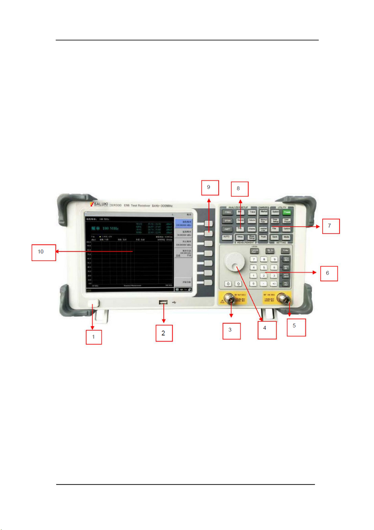
1.1 Front panel................................................... ................................................... ..........11
1.4 Detailed description of the function keys................................... ................................................13
3.1.1 Main functions................................................... ...............................................23
1.3 Key control area................................................ ................................................... ...12
EMI Receiver Instructions for Use

ÿ
ÿ
3.3.2 Detailed operation guide...................................... ...................................................28
4.2.2 Measurement of Injection Probe Conduction Sensitivity................................... ................................37
5.2 Save operation................................................... ................................................... ......44
4.2.1. Measuring interference on power lines and signal lines with a current detection probe............................................................................................................ 36
4.2 Detection probe and injection probe................................... .................................................35
4.1 EMI Receiver and Near Field Probe Operation................................... ...................................30
5.1 Limit line editing of the instrument................................................... ...................................................39
4 Accessory test operation guide..................................... ................................................... ..29
5 Editing and saving of instruments................................................... ................................................... ....38
4.1.2 Use a near-field probe to find electromagnetic leakage in the gap of the chassis.......................... ......32
5.1.2 Limit line parameters and operation steps................................... ...................................42
5.1.1 Limit lines of the instrument................................... ...................................41
4.1.1 Near-field probes................................................... ................................................31
4.1.4 Quantitative testing (absolute value measurement) is possible with near-field probes .................. 34
6. Precautions for using the instrument................................................... ................................................... ..46
4.1.3 Use a near-field probe to find the source of electromagnetic interference on the PCB........................... ......33
7
EMI Receiver Instructions for Use

Figure 1.2 EMI receiver measurement block diagram
ÿÿÿÿÿÿÿÿÿÿÿÿÿÿÿÿÿÿ
Figure 1.1 EMI Receiver
8
1. Receiver Introduction
EUT
LISN
Current sense probe
EMI receiver
Hardware circuit
low noise amplifier
EMI Near Field
Diagnostic Probes
Spectrum Module
Common differential
mode splitter
Trace source
EMI Receiver Instructions for Use
Measurement accessories
Processing Module

1. Power switch
9.soft menu setting area
ÿÿÿÿ
9
8.System function area
3.Tracking source output terminal
8
13
2.USB interface
5.RF input terminal
7.Cursor keypad
The EMI receiver provides the user with a simple and well-defined front panel for basic operation. panel
5
10.display screen
It includes a knob and function keys, and the function of the knob is similar to that of other instruments. There
are 7 function soft keys on the right side of the display, keys, through which different options of the current
menu can be set. Other keys are function keys, through them, it is possible to enter different function
menus or directly obtain specific function applications.
4
10
6.parameter input area
7
6
4.Knob
2
1.1 Front panel
Figure 1.3 Front panel of ER series EMI receiver
9
EMI Receiver Instructions for Use

5
2.LAN interface
2
5.USB interface
4
6.headphone jack, audio output
3
1.RS232 interface
4.VGA interface
7
3.10MHz reference signal input/output connector
7.EMI receiver power input socket
6
1
1.3 Button control area
1.2 Rear panel
Figure 1.4 ER series EMI receiver rear panel
10
EMI Receiver Instructions for Use

Figure 1.5 Explanation diagram of button and knob control area
1.4 Detailed Description of Function Keys
11
Function details
2.Parameter setting keypad
Function key detailed table
1.Common function key area
Functional positioning
4.System function key area
function key
3.Cursor measurement function key area
EMI Receiver Instructions for Use

【Trig】
Scanning Time Set
manual/manual), frequency offset (default 0Hz), frequency reference (internal
【SPAN】
Blanking, viewing, trace calculation
Reference units (dBm, dBuV, dBpW, dBmW, dBmV, W,
【BW】
【Detector】
Resolution Bandwidth Set
Automatically test RF IN 50ÿ input RF signal
Analyzer Setup Keypad
Trace (1, 2, 3), Refresh, Max Hold, Min Hold,
Type (Linear/Logarithmic), Reference Bias (0dB),
【AUTO】
Ruler (on/off), label (on/off)
Span (automatic/manual), full span, zero span, previous span
Span setting
Trigger mode setting
Full screen display, window scaling (on/off), display lines
continued), video bandwidth (on/off)
Frequency parameter setting
【FREQ】
【Trace】
V), pre-amplification (automatic/manual)
Auto Search
【Sweep】
Amplitude setting Reference level, attenuator, scale/div (default 10dB), scale
Trace settings
-25dBm (on/off), grid (on/off), amplitude
internal/external), LF channel (on/off)
【Display】
【AMPT】
Scan point settings
EMI Receiver Instructions for Use
12
Detection mode setting automatic, normal, positive peak, negative peak, sampling
resolution bandwidth (auto/manual), resolution step (default/continuous
the scanning time (automatic/manual), single scanning,
continuous scanning,
center frequency, start frequency, stop frequency, frequency step (from
Display settings
automatic, video (-20.00dB), external (rising edge/falling edge)

【Peak】Peak measurement key Maximum search, next peak, left peak, right peak, minimum
【Marker】Frequency marker indication
setting
on/off), 75ÿ impedance compensation 0.00dB (on/off)
Orientation (Landscape/Portrait)
storage (screenshots, trace data, user status)
Difference, Off, All Off, Marker List (On/Off)
Value search, peak search (on/off)
【Marker Fctn】
Default state, cannot be replaced
System information, configuration I/O, power on/reset, date/time,
Backlight adjustment, user calibration, system service, screen refresh (on
Frequency standard function key area
Frequency, Frequency StandardÿStop Frequency, Frequency StandardÿReference Level
【Preset】
Measurement function settings
【Meas】
【Print Setep】
【System】
Channel power (on/off), occupied bandwidth (on/off)
【Meas Setup】
on, off), frequency counting (on/off)
paper size, printing language, printing type (black and white/color),
Function off, NdB3.00 (on/off), frequency standard noise (on
【Marker 】
Measurement function keypad
System Function Keypad
EMI Receiver Instructions for Use
13
time spectrum (on/off), adjacent channel power (on/off),
Measuring settings
key frequency marker (1, 2, 3, 4, 5), trace (1, 2, 3), normal,
Frequency marker function key
Frequency marker indication
change key
Frequency marker center frequency, frequency marker frequency step,
frequency marker start
system setting key
System reset
Print setup

2.Backspace key
EMI receivers, spectrum analyzers, network measurements, filter simulations
1.Knob
mode selection key
5.Arrow keys
3) Network measurement interface
4.Number keypad
【Mode】
2) EMI receiver user interface
3.Confirm key
1) Spectrum analyzer user interface
real
Figure 1.6 Explanation diagram of parameter input interface
The 3 modes of the user interface are as follows:
14
1.5 Parameter input interface
EMI Receiver Instructions for Use

2.1 EMI Receiver
Figure 2.2 EMI receiver user interface
15
2. Introduction to EMI Receiver
2.1.1 EMI receiver instrument interface
5
NO.
3
NO.
2
1
6
4
EMI Receiver Instructions for Use
Name Description Name Description

Figure 2.3 EMI receiver CE102 operation interface
3 6
Attenuation value
Display current BW value
mark
Measurement Item
bit
Display amplitude value range resolution band
Test report style:
4
Single display of the current amplitude value
Amplitude sitting
bit
5
Width
Amplitude sheet
1
2
16
EMI Receiver Instructions for Use
Displays the value of the attenuator
Standard baseline Show standard limit curves
Displays the current measurement
item

4
9
Conduction: ≤20kVA, >20kVA;
GJB151A
Conduction: power terminal, below 700W, 700W-1000W, above 1000W
3
RE102 (ships, submarines, air, ground)
JAPAN lamps
5
FCC Part 15B
Conduction: GB9254A, GB9254B
conduction: power terminal, below 700W, 700W-1000W, above 1000W
GB4824
GJB151B CE102 (28V, 115V, 220V)
FCC conduction
7
CE102 (28V, 115V, 220V)
Conduction: power terminal, below 700W, 700W-1000W, above 1000W
EN55011
1
6
Harassment: power terminal, below 700W, 700W-1000W, above 1000W
Standard
Radiation: GB9254A, GB9254B
GB9254
10
GB17743 conduction, GB17743 radiation
8Conduit, Harassment
GB17743
Harassment: power terminal, below 700W, 700W-1000W, above 1000W
RE102 (RE102-1, RE102-2, RE102-3)
2
EN55015
Remark
EN55014
Harassment: power terminal, below 700W, 700W-1000W, above 1000W
Conduction
11
2.1.2 EMI Receiver Test Standards
17
EMI Receiver Instructions for Use
SN.
JAPAN home
appliance

EMI Receiver Instructions for Use
2.2.3.1 Common parameter settings
18
2.1.3 Common EMI Receiver Operations
The spectrum display area displays the range, which can display 100dB dynamic range by default, and the minimum level is 0dBuV.
Operation steps: [FREQ]→[Stop Frequency], the default is 1GHz, after adjustment, the spectrum displays the regional frequency
【Stop frequency】
Operation steps: [AMPT] →[level range], the default is 100dB, and the adjustable range is 10dB~200dB
auto range adjustment
Adjustable range
[AMPT] →[Minimum level], default 0dBuV
【attenuation】
-93dBuv~297dBuV
Common parameters of the receiver include: start frequency, stop frequency, attenuation, preamplification, dynamic range, bandwidth,
Operation steps: [AMPT] →[Attenuation], the default is 9dB, the range of change is 0~39dB, 3dB step
,
【Pre-amplification】
After the setting is completed, the dynamic range of the spectrum display area is automatically updated.
Measurement time, scan mode, etc.
【bandwidth】
Operation steps: [AMPT] →[Pre-amplification], the default is off, and the gain can be increased by 20dB after opening
【Start Frequency】
Operation steps: [FREQ]→[Start Frequency], the default is 30MHz, after adjustment, the frequency spectrum displays the area
frequency
【Dynamic Range】
rate range auto-adjust

EMI Receiver Instructions for Use
2.2.3.2 Fixed frequency measurement
Operation steps: 【Meas】→【Measuring time】, the default is 10ms
Operation steps: [Sweep] →[List Sweep] / [Current Settings]
Average value (AVG), effective value (RMS) four kinds of detection results display, each detection value has a maximum hold
【Scan mode】
[List Scan] mode provides 10 independent measurement intervals, and each interval can be set for different measurements
Operation steps: [BW] →[Resolution Bandwidth] Receiver mode provides
Hold function in dBuV. As shown in the figure above, the maximum value (MAX) detection, the current real-time value is 47.56dBuV,
The historical maximum is 48.46dBuV. After the receiving frequency is modified, the maximum hold value is automatically reset.
10Hz/100Hz/200Hz/1kHz/9kHz/10kHz/100kHz/120kHz/1MHz total 9 file resolution
Parameters, executed in interval order during measurement
Bandwidth, you can cycle through the up and down arrow keys, and the menu area displays commonly used
【Current setting】Quick measurement, equivalent to an interval measurement
200Hz/9kHz/120kHz/1MHz four-speed resolution bandwidth
Fixed frequency measurements are automatically activated when not scanning, and automatically hide after starting a scan or measurement
【measure time】
The fixed frequency is determined by the receiving frequency, and the maximum value (MAX), quasi-peak value (QPK),
Receiver measurement time range: 100us~100s
19
This manual suits for next models
3
Table of contents