SaMASZ RP 110 User manual

SaMASZ Sp. z o.o.
ul. Trawiasta 1
16-060 Zabłudów
Poland
tel. (+48) (85) 664 70 31
fax (+48) (85) 664 70 41
e-mail: samasz@samasz.pl
www.samasz.pl
OPERATOR’S MANUAL
ROAD SHOULDER CUTTER
RP 110
The orginal operator’s manual
ENGLISH
Serial number
IN335EN002
05.01.2015
EDITION No 2

2
RP 110
ROAD SHOULDER CUTTER
OPERATOR’S MANUAL
Apart from this Operator's Manual observe also operator's manual for KWT or Camel
extension arm.
This instruction manual is an indispensable part of each road shoulder cutter and its goal is to
familiarise the user with the proper operation and use of the machine, as well as with the related
hazards. Read this instruction manual carefully and follow the safety instructions before running the
machine for the first time. Keep the instruction manual for future reference.
The road shoulder cutter should be used, operated, and repaired only by persons familiar with
its maintenance and safety rules.
The accident prevention regulations and all basic occupational health and safety regulations,
as well as traffic regulations should always be observed.
In case of any doubts related to the start-up and operation, contact the manufacturer’s service
centre.
The manufacturer will not be liable for any damage resulting from unauthorised repairs or
changes to the road shoulder cutter which have been made without the manufacturer’s consent.
If the road shoulder cutter is sold to another user, the instruction manual must be also handed
over with a written confirmation of this fact.
CAUTION:
The instructions in this instruction manual marked with this sign and warning
signs placed on the machine inform about hazards.
CAUTION:
Keep this manual for future reference.
Well-proven design with thousands of machines in regular use in many countries and quality materials
ensure high durability and reliability of SaMASZ machines.
We congratulate you on the purchase of your new SaMASZ machine and wish you much pleasure and
the very best work results through the years to come.

3
OPERATOR’S MANUAL
ROAD SHOULDER CUTTER
RP 110
Contents page
1. IDENTIFYING THE MACHINE.................................................................................................................4
2. INTRODUCTION ...................................................................................................................................4
3. SAFETY PRECAUTION ..........................................................................................................................5
3.1. Safety rules................................................................................................................................... 5
3.2. Safety labels ................................................................................................................................. 8
3.3. Residual risk ................................................................................................................................10
4. OPERATING.......................................................................................................................................11
4.1. Intended use and design...............................................................................................................11
4.2. Steerage ......................................................................................................................................12
4.3. Transport position and drives........................................................................................................12
4.4. Installing......................................................................................................................................13
4.5. Initial adjustment..........................................................................................................................14
4.6. Preparing for operation.................................................................................................................14
4.7. Safe start uo and shut down..........................................................................................................14
4.8. Operation.....................................................................................................................................15
4.9. Proceedings in case work unit is locked ........................................................................................15
4.10. Malfunctions and their repair ....................................................................................................16
5. EQUIPMENT AND FITTINS ..................................................................................................................17
6. OPERATING.......................................................................................................................................17
6.1. Maintenance and service ..............................................................................................................17
6.2. After-season maintenance and storing ..........................................................................................19
7. MAINTENANCE AND STORING ...........................................................................................................19
8. TRANSPORT AND DELIVERY...............................................................................................................19
9. SPECIFICTIONS .................................................................................................................................20
10. DISASSEMBLY AND SCRAPING...........................................................................................................21
10.1. Disassembly.............................................................................................................................21
10.2. Scraping...................................................................................................................................21
10.3. Environment.............................................................................................................................21
11. WARRANTY .......................................................................................................................................22
11.1. Warranty card...........................................................................................................................22
11.2. Warranty terms.........................................................................................................................22
11.3. Warranty repairs record.............................................................................................................24

4
RP 110
ROAD SHOULDER CUTTER
OPERATOR’S MANUAL
1. IDENTIFYING THE MACHINE
Each road shoulder cutter can be identified with a nameplate, which is permanently attached to
the frame, as shown below Fig. 1.
Fig. 1. Data place location
Data plate includes:
❑name and adress of the manufacturer,
❑model year,
❑CE marking means, that the produce conforms
❑version number,
to 2006/42/EC Directive and harmonized standards,
❑machine weight,
❑machine symbol,
❑id number,
❑date of manufacture,
❑barcode.
CAUTION:
In case the operator's manual is unclear or illegible all necessary information
can be obtained from manufacturer or the dealer.
CAUTION!
The nameplate has the status of a document and it is forbidden to change its
contents or make it illegible.
It contains the necessary information to communicate with the supplier in
case of any questions or problems.
2. INTRODUCTION
❑This operator’s manual should be considered as the basic tree stump grinder’s equipment. If the
machine is handed over to another operator, it should be in working condition and given away
along with operator’s manual and it’s other basic equipment.
❑Before starting the operation of the road shoulder cutter, the user must read and understand the
instruction manual and the safety regulations.
❑Respecting warnings herein shall ensure full operation safety.
❑If you have any questions related to commission and operation of the tree stump grinder, please
contact the manufacturer.
❑This operator’s manual is an indispensable part of any machine and is intended to familiarize
future user with principles of proper operation and use of the machine as well as the risks
involved.

5
OPERATOR’S MANUAL
ROAD SHOULDER CUTTER
RP 110
3. SAFETY PRECAUTION
CAUTION!
The road shoulder cutter is a dangerous machine. The machine can only be
operated by personnel who have learned this manual.
Every user of the road shoulder cutter should be completely aware of the existing hazards and
should know how to avoid them.
Always have workwear, protective shoes and appropriate personal protective equipment when
using the road shoulder cutter.
❑Protective helmet,
❑Ear protection,
❑Protective gloves.
Operator should always have a first-aid kit within his reach.
3.1. Safety rules
Operating
❑During operation of the machine the Regulation of the Farm Ministry and Food Economy
(Rozporządzenie Ministra Rolnictwa i Gospodarki Żywnościowej) from 12.01.1998 dealing with
safety and hygiene during the operation of tractors, machinery, tools and equipment used for
farming (Journal of Laws No. 12/98 item 51), should be observed.
❑Apart from this Operator's Manual observe also operator's manual for KWT or Camel extension
arm.
❑Do not use the road shoulder cutter for any purposes other than its intended use.
❑Do not introduce any design modifications without prior arrangements with the Manufacturer.
❑Unfamiliarity with the instruction manual may result in damage to the machine.
❑The machine must not be operated by minors or handicapped persons.
❑Observe all safety signs, warnings or warning signs placed on the machine.
Attaching
❑The assembly and disassembly of the road shoulder cutter on the extension arm should be
performed when the arm is attached to the tractor, when the entire assembly is immobilised by
the tractor parking brake.
❑When connecting hydraulic hoses to the road shoulder cutter nozzles wear protective gear such
as eyewear, gloves and clothing.
❑Mount and dismount the road shoulder cutter from extension arm on an even and paved surface
while keeping particular attention.
❑Tractor's 3-point linkage should be adjusted with tensioning chains, so as to ensure a stiff
connection between the tractor and the extension arm, onto which the machine is to be mounted.
❑Tractor with the mounted aggregation of the extension arm and the road shoulder cutter should
be balanced so as to provide the stability of the aggregation including the tractor and the
extension arm.
❑In order to mount the machine on the extension arm use original fittings and safety devices only.

6
RP 110
ROAD SHOULDER CUTTER
OPERATOR’S MANUAL
❑When connecting hydraulic hoses to the tractor's hydraulic connectors make sure, that the
hydraulics on either the tractor or the extension arm aggregate are pressure free.
❑Before connecting the hydraulics reduce pressure in hoses.
Transport
❑When driving on public roads always respect the local traffic regulations concerning warning
lights.
❑Remove or partially disconnect the PTO shaft on the tractor side for the transport of the
assembly.
❑While transporting the above aggregation mount remote warning light device and warning triangle
for a slow driving vehicle.
❑During transport, always set the machine in its proper and safe transport position. See section
3.3.
❑Any modifications in the machine's position are possible only if no vehicles or unauthorized
personnel are around (children in particular).
❑Always adjust the driving speed to the road conditions.
❑Do not drive over 25 km/h (15 mph).
❑In case of damage to the hydraulic system during transport, the extension arm actuator should be
secured with a special lock (the c-rail on the actuator piston rod).
Operation
❑When operating on public roads always respect the local traffic regulations and provisions
concerning warning lights.
❑Admissible slope, on which the machine is able to operate is provided by the Manufacturer.
Angular value for safe operation on slope is 8º.
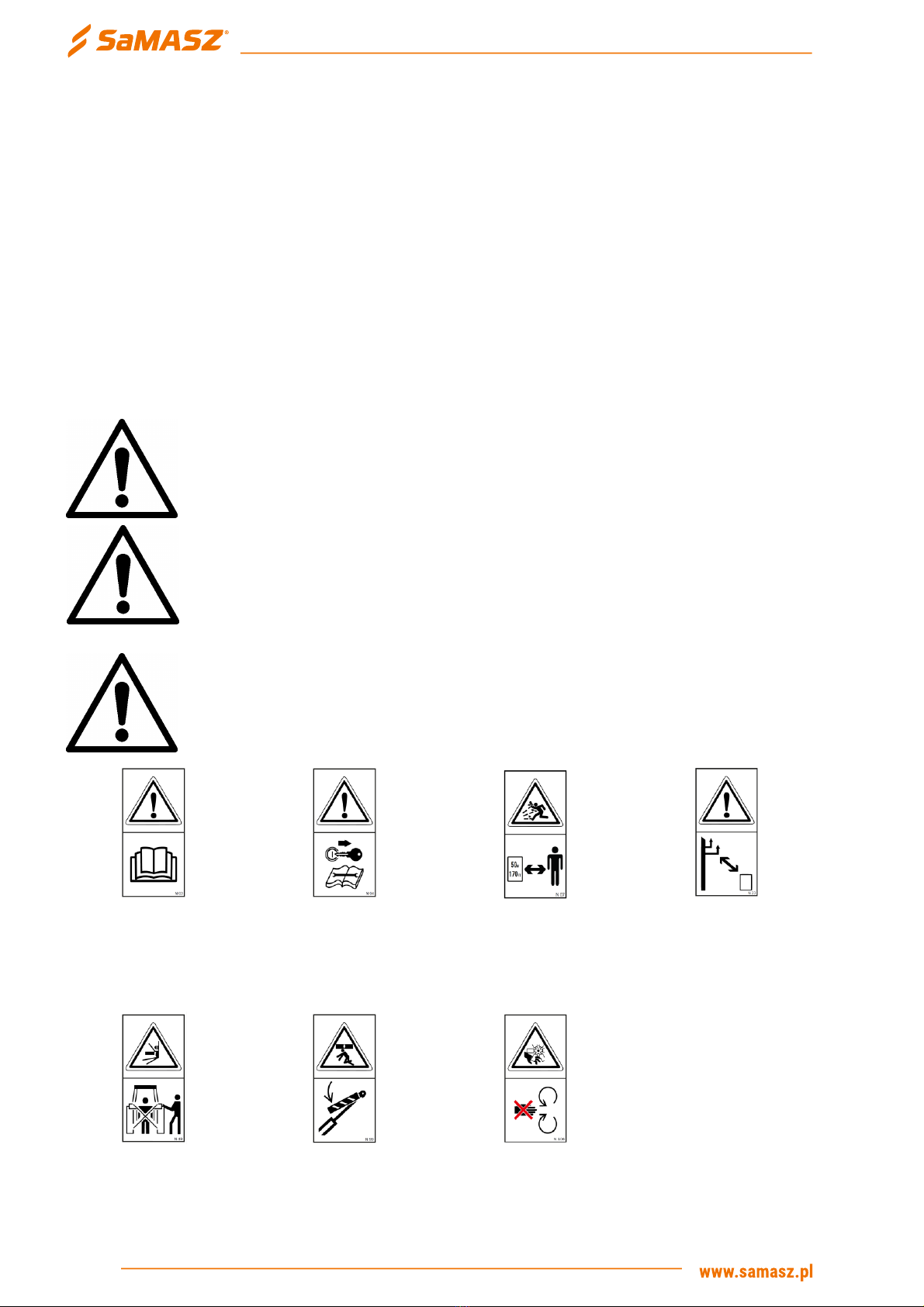
❑Unauthorised personnel and animals should keep away from the grinder for a safe distance, which
is at least 10 m from the machine. Keep particular attention when operating near roads and lanes,
where presence of unauthorized personnel is likely.
❑When operating the aggregation of arm and road shoulder cutter, make sure the tractor is always
equipped with operator's cabin.
❑When operating the aggregation of arm and grinder, make sure the tractor is always equipped with
operator's cabin.
❑Before starting the tractor, make sure that all drives are disconnected and control levers for
hydraulics are in neutral position.
❑Before moving, make sure whether there are no unauthorised personnel directly nearby the
machine, give an acoustic signal.
❑Never leave the tractor’s engine running without any supervision. Before leaving the tractor, turn
the drive off, set the aggregation of tractor and extension arm and the tree stump grinder in a
standstill position and remove the ignition key.
❑For any break in the machine operation, disconnect the drive.
❑The road shoulder cutter should be operated at 540 rpm of the PTO (applies to SaMASZ extension
arms).
❑All machine movements must be performed only from the operator’s seat. Do not control the
machine outside of the tractor cab.
❑The operating speed of the extension arm-cutter assembly should be adjusted to the operating
conditions, such as: the amount of removed material, its density, terrain unevenness.

7
OPERATOR’S MANUAL
ROAD SHOULDER CUTTER
RP 110
❑Do not operate after dusk.
❑Do not leave the tractor-arm system on slopes without additional protection.
❑Do not operate with damaged or missing guards.
Inspection and repair
❑Perform any inspection, repair and maintenance works as well as cleaning parts or assemblies
when the drive is switched off and there is no pressure in the hydraulics, having taken the ignition
key off and set the aggregation of tractor and machine in a standstill position.
❑Inspect bolts and other fasteners regularly. Do not operate with damaged or worn fasteners.
❑Replace damaged or worn (aged 5 years or older) hydraulic hoses and other hydraulic parts as
recommended by the Manufacturer.
❑Do not perform any repair works underneath the lifted machine’s assemblies, unless protected
against free falling.
❑Check the condition of the cutting blades before each operation. If they are blunt, return them for
renovation. Replace if damaged or worn.
❑Use only original spare parts ordered at our store or at your dealer.
❑During operation, maintenance and adjustment, always wear protective gloves, shoes and clothing
without loose elements, belts, etc. Always respect warnings on safety labels attached to the
machine.
❑When operating the hydraulics, always wear protective eyewear and gloves. Hydraulic oil leaking
under pressure (20 MPa) may penetrate the skin and cause its irritation thereafter. In such case,
visit a doctor immediately.
❑In the event of a serious failure, please call for technical service, and if an accident (in this case:
road accident) occurs, respect first aid rules and contact responsible authorities.
Storage
❑Machine should be stored under a roof and protected against access of animals and unauthorised
persons who could get injured.
Transport
❑Both the driver and the carrier are responsible for the cutter's safe transport. Any equipment and
parts must be secured for transport.
❑Handle with the lifting devices only by attaching to rigid elements of the road shoulder cutter, such
as the support frame and the mounting plate.
❑Use the lifting devices and accessories with a lifting capacity greater than the weight of the road
shoulder cutter indicated on the nameplate.
❑Secure the road shoulder cutter on the vehicle load bed in such a way as to prevent its movement.
WARNING!
The person in charge of the machine's transport shall be responsible for
securing the danger area and performing the work.

8
RP 110
ROAD SHOULDER CUTTER
OPERATOR’S MANUAL
Qualifications of operator
To provide safe machine operation each person being the machine operator must meet the
following requirements:
❑Operator should hold driving license, have ability to drive vehicles safely and know road traffic
rules.
❑Operator must be in proper physical condition to be able to operate the machine.
❑Operator must not be under the influence of alcohol, drugs and medicines, which all have
influence on vehicle driving and machine operation.
❑Operator should be familiarized with this manual and follow its provisions.
❑Operator should be familiar with working principles of both the tractor and the machine, and be
able to recognize and avoid hazards resulting from operation of the aggregate.
3.2. Safety labels
CAUTION!
Always comply with safety decals describing risks, and warning signs placed
on the machine.
CAUTION!
•All warning decals (labels) should be clean and legible.
•Lost or damaged decals (labels) must be replaced with new ones.
•New decals (labels) may be ordered at the Manufacturer.
CAUTION!
The spare assemblies used during the repair of the machine should have all
the safety signs provided by the manufacturer.
N-3
Before use read the
operator’s manual
N-4
Disconnect the machine
before approaching any
service or repair works
N-7
Operating is forbidden
when any person is
within the danger area of
50 m / 170 ft
N-23
Caution: power lines
N-49
Do not remain in
machine’s swinging area
N-99
Danger of crushing
N-106
Warning: rotating
elements

9
OPERATOR’S MANUAL
ROAD SHOULDER CUTTER
RP 110
Wear protective eyewear
N-100
Wear protective gloves
N-52
Wear protective clothing
N-101
Wear protective helmet
N-102
Wear ear protection
N-103

10
RP 110
ROAD SHOULDER CUTTER
OPERATOR’S MANUAL
3.3. Residual risk
CAUTION!
There is a residual risk mainly due to incorrect behaviour of the machine
operator and failure to comply with the instruction manual.
CAUTION!
When presenting the residual risk, the road shoulder cutter is treated as a
machine which has been designed and manufactured in accordance with the
state of the art on the date of its manufacture.
Trapping, pinching hazard.
This hazard is posed by running operating parts when the position of the road shoulder cutter is
changed during operation.
Danger of cutting limbs off.
Contact between cutting knives and body may lead to serious injuries, and in extreme cases
amputation of limbs or even death. Failure to pay enough attention when operating the machine
nearby unauthorized personnel may cause an accident.
Injury hazard.
It occurs during the replacement of the operating parts with sharp edges. Always use protective
gloves for all repairs and maintenance work.
Projection hazard.
Projection is one of the most dangerous accidents that can occur during the operation of the
road shoulder cutter. “Projection” means an uncontrolled and rapid movement of the processed
material or its fragments (stones, pebbles, branches, etc.). If the human body is hit directly by the
material, this may cause, depending on the weight, size, speed, and location of the impact: bruises,
skin perforation, loss of an eye or teeth, or even death as a result of damage to organs and extensive
internal bleeding.
Skin and eye irritation hazard.
When connecting/disconnecting the hydraulic hoses to/from the tractor’s hydraulic outlets,
make sure that both the tractor’s hydraulic system and the extension arm are depressurised.
Otherwise, the oil may leak at a pressure of approx. 16 MPa. It is also the case for damaged hoses.
That is why you must wear safety glasses and protective gloves when operating the hydraulic system.
Inspect regularly the hydraulic system hoses.

11
OPERATOR’S MANUAL
ROAD SHOULDER CUTTER
RP 110
PROHIBITIONS!
Keep the following in mind when using the machines.
❑Do not clean, adjust, or repair the machine while it is in operation.
❑Never change the sequence of operations described in the instruction manual.
❑Never operate the road shoulder cutter when it is not in good working order.
❑Never approach the moving parts of the machine.
❑When performing repairs or maintenance of the road shoulder cutter, always follow the
instructions in the instruction manual. The drive of the tractor must be disconnected.
❑Before you start, focus exactly on what you need to do.
❑Never operate the road shoulder cutter while under the influence of alcohol, drugs, or
medications that impair motor skills.
❑The road shoulder cutter must not be operated by unauthorised or untrained personnel.
❑Always pay attention that there are no bystanders or animals in the vicinity of the road shoulder
cutter.
4. OPERATING
4.1. Intended use and design
The machine is intended for removing and levelling road shoulders, ground pedestrian paths,
and other irregular formations on the ground. The operation of the machine for other purposes
constitutes use contrary to the intended purpose. The hardened wear-resistant steel cutting blades
enable operation on the soils of III category.
The operation of the machine consists in lowering the cutting blades into the ground and
transferring the waste material outside the machine working zone. The maximum processing depth is
20 cm. A few crossings should be made to level the soil shoulders of higher height.
The RP 110 road shoulder cutter is designed to work with the following extension arms:
•KWT 550, KWT 550 E, KWT 550 EP,
•KWT 650 , KWT 650 E, KWT 650 EP,
•KWT 651 E, KWT 651 EP,
•CAMEL 900, CAMEL 900 EP.
It is possible to adapt the road shoulder cutter to another extension arm with the same
mounting plate or another arm after it has been adapted.
When using the machine, do not:
•attach ropes, chains or towing hooks,
•process a rocky or bituminous surface.

12
RP 110
ROAD SHOULDER CUTTER
OPERATOR’S MANUAL
Fig. 2. Mounting plate
The road shoulder cutter consists of a single-part fixed support frame with a mounting plate,
and a movable worm shaft with replaceable cutting blades attached to it. The worm shaft is moved
via a chain drive by a hydraulic motor attached to the chassis. The operating principle and the
connection method according to the hydraulic diagram are shown in Fig. 3b.
Fig. 3a. Road shoulder cutter RP 110 –1,2 m
The description of the road shoulder cutter.
A –Mounting plate of the machine.
E –Hydraulic motor.
B –Support frame.
F –Connection ports of hydraulic hoses.
C –Worm shaft.
G –Support wheel.
D –Milling blades.
H –Chain drive guard.
Fig. 3b. Hydraulic schema
4.2. Steerage
The road shoulder cutter is controlled by the extension arm via its individual control panel.
4.3. Transport position and drives
The transport position of the road shoulder cutter attached to SaMASZ extension arm is in
accordance with the transport position of the arm. See the Fig. 4.
D
C
E
G
H
F
B
A

13
OPERATOR’S MANUAL
ROAD SHOULDER CUTTER
RP 110
If the road shoulder cutter is installed on another type of an extension arm, the assembly of the
machine and the extension arm should be folded to the most compact position.
❑During the transport of the cutter-arm assembly, use all transport safety devices provided for the
control and structure of the extension arm.
❑Dismount the PTO shaft for transport. Provide proper marking and lighting of the aggregated
machines for a low-speed vehicle to comply with road traffic provisions.
❑Driving speed should always be adjusted to current road conditions.
❑Transport speed on public roads cannot exceed the mean speed of 25 km/h (15 mph).
Fig. 4. Transport position
4.4. Installing
To connect properly the road shoulder cutter to the extension arm, proceed as follows:
❑place the pallet with the road shoulder cutter on a level and hardened ground,
❑drive up the tractor with the attached extension arm and set the arm mounting plate so that it is
aligned with the mounting plate of the cutter.
❑secure the tractor against movement with the parking brake,
❑attach the road shoulder cutter mounting plate to the extension arm mounting plate with 6 M14
screws and nuts,
❑connect the hydraulic hoses with quick-release couplings; pay special attention to connect the
power supply line of the road shoulder cutter to the power supply connector P(+) of the extension
arm, and connect the return line of the cutter to the return connector T(-) of the extension arm
(Fig. 5).

14
RP 110
ROAD SHOULDER CUTTER
OPERATOR’S MANUAL
Lift the machine slightly above the pallet and check the condition of the screw connections (see
Table 1) and also check for any visible damage.
Start the road shoulder cutter to check its correct connection and operation.
Fig. 5. Markings of hydraulic hoses
CAUTION!
When connecting and inspecting the machine, follow any and all safety
conditions provided herein.
4.5. Initial adjustment
Machine is factory adjusted and requires no additional adjustments. If any signs of improper
operation of the grinder are found, please contact the Manufacturer's service.
4.6. Preparing for operation
Before operation do the following:
❑carefully check that the machine is in good working order and free of play and damage. Pay
particular attention to the condition of the screw connections of the cutting blades,
❑remove all guards, locks, and safety devices installed on the cutter-arm assembly,
❑connect the PTO shaft to the tractor,
❑having made sure there is no unauthorized personnel around, start machine with no load and
reach the pre-set PTO rpm rate, and then shut down and check for tightness,
❑if the tree stump grinder's condition and its idle operation raise no doubts, start operating.
4.7. Safe start uo and shut down
Before operating make sure there are no unauthorized personnel or animals within the range of
10 m. Next set the grinder in the mean working position and start it afterwards.
Before stopping the road shoulder cutter, finish the work by lifting the machine above the
processed surface. Next, turn off the machine drive and then you can proceed with handling the
extension arm to fold the arm-cutter assembly to the transport position.

15
OPERATOR’S MANUAL
ROAD SHOULDER CUTTER
RP 110
4.8. Operation
In order to ensure proper high-quality operation, as well as to maintain machine durability follow
these rules:
❑Respect work safety and traffic rules solely.
❑keep hydraulic oil consumption for machine supply pump at max. 70-100 l/min. For SaMASZ
extension arm such demand is achieved at tractor’s PTO shaft rpm of 540 rpm.
❑Before starting the operation, it is recommended that the operator should adjust the road
shoulder cutter in a position adequate to the task and then the operator should not change its
position throughout the entire processed path. This type of operation ensures safety and good
look of the processed surface.
❑Remember to adjust the driving speed to the depth and the compactness of the removed material,
so as not to overload the machine and thus not to jam it.
❑Do not make any movements with the extension arm during the operation. Steady extension arm
contributes to the high quality of the performed work.
❑When the road shoulder cutter and the extension arm are positioned as shown in Fig. 6, start the
machine and lower it slowly to the ground level.
❑In the case of long operating cycles, it is recommended to inspect regularly the condition of the
cutting blades, screw connections, and the entire road shoulder cutter.
❑To ensure precise control over the extension, adjust the throttle valves located on the actuators
with the knobs.
Fig. 6. Operating position of the road shoulder cutter with the extension arm
4.9. Proceedings in case work unit is locked
❑perform any works at the machine only with its drive turned off and no pressure present in the
hydraulics,
❑lower adaptor onto the ground,

16
RP 110
ROAD SHOULDER CUTTER
OPERATOR’S MANUAL
❑remove the ignition key and secure the vehicle against uncontrolled movements or unintended
start up,
❑wear protective gloves and remove the part which causes the machine's locking.
4.10. Malfunctions and their repair
Defect
Reason
Repair
Machine is not
working
Damaged or worn cutting blades
Renovate or replace with new ones.
Too low PTO rpm
Increase the engine speed
Worn, damaged hydraulic engine
Recover hydraulic engine or replace
Damaged or torn bolts securing
hydraulic engine
Replace
Not tight hydraulics
Seal or tighten connectors
Improperly adjusted or damaged
oil distributor
Adjust or replace
Worm shaft rotates in the
opposite direction
Replace the wires
Not tight hydraulic assembly,
broken or torn hydraulic hoses
Remove any non-tightness, replace
hoses
The road shoulder
is not equal
Blunt or damaged cutting blades
Renovate or replace with new ones
Rapid, non-accurate movements
of the extension arm
Unaligned throttle valves on the
extension arm actuators
Low speed of the
worm shaft
Improper tractor's PTO rpm
engaged
Switch tractor's PTO shaft rate to 1000
rpm
Low rpmat tractor's PTO
Increase tractor's engine rotary speed
Worn hydraulic engine
Replace
Not tight hydraulics
Seal
Loud operation
Loose mounting bolts of
hydraulic engine or tree stump
grinder’s mounting plate
Tighten bolts
High vibration of
the road shoulder
cutter and
extension arm
Loose cutting blades
Tighten bolts
Loose screw connections
Tighten bolts
No cutting blade
Attach the cutting blade
Oil leak
Improperly bolted connecting
nozzles
Bolt connecting nozzles
Worn, damaged sealants, fittings
Replace sealants, fittings
Not tight hydraulic cylinder
Recover
Replace

17
OPERATOR’S MANUAL
ROAD SHOULDER CUTTER
RP 110
Carry out any works related to the replacement of the worn or damaged parts only when the
machine is switched off and when you have read and understood the instruction manual.
The machine must be put in standstill according to the instructions contained in the instruction
manual. When repairing or replacing worn or damaged parts, wear protective gloves, covered
footwear and protective clothing without loose parts. When working with the equipment raised, secure
it with supports. When replacing parts with sharp edges, use personal protective equipment and tools
intended for this purpose.
When the activities related to the replacement of defective parts are complete, install all guards
and safety devices.
5. EQUIPMENT AND FITTINS
The machine are sold with the following standard equipment:
❑road shoulder cutter with parts required for connection,
❑warranty card,
❑operator's manual with spare part list and the Declaration of Conformity,
❑spray paint (150 ml).
Equipment and spare parts:
❑worm shaft,
❑hydraulic motor,
❑milling blades,
❑hydraulic hoses,
❑all other parts in the Parts Catalogue.
Accessories:
❑warning signs with combined lamps and reflective parts,
❑warning triangle.
CAUTION!
Use only original SaMASZ accessories and spare parts. The parts supplied by
unknown sources may adversely affect the functioning of the machine and the
safety of operation, and have a lower durability.
CAUTION!
SaMASZ is not liable for any damage resulting from the use of non-original
parts and accessories.
6. OPERATING
6.1. Maintenance and service
Before each operation of the shoulder milling machine:
❑make sure that the tractor and the extension arm to which the road shoulder cutter is attached
work correctly,
❑check the screw connections of the cutting blades and tighten the bolts if necessary,

18
RP 110
ROAD SHOULDER CUTTER
OPERATOR’S MANUAL
❑Examine torque of all bolts and nuts Table 1,
Table 1. Torque values for bolts
❑check the condition of hydraulic hoses and connections,
❑check the condition of the cutting blades and, if necessary, renovate or replace them with new
ones,
❑replace damaged parts.
After 4-5 hours of work:
❑check the screw connections, in particular screw shaft connections, cutting blades, and tighten if
necessary according to Table 1,
❑check the condition of the hydraulic hoses and connections,
❑check if the cutting blades are suitable for further operation.
After finishing the operation with the road shoulder cutter:
❑clean and wash the machine thoroughly.
Fig. 7. Adjustment of the height of the support wheel
To adjust the operating depth of the milling machine, it is possible to change the height of the
support wheel. For this purpose, when the road shoulder cutter is raised above the ground, remove pin
1(Fig. 7) unlock pin 2, then pull it out and move the support wheel to set an appropriate, one of the
four, operating heights of the cutter.

19
OPERATOR’S MANUAL
ROAD SHOULDER CUTTER
RP 110
The parts whose damage may pose threat to the operator’s health and safety are: the working
tool and the damaged protective covers.
6.2. After-season maintenance and storing
Carry out all the actions in accordance with the section: “Maintenance and storage”.
7. MAINTENANCE AND STORING
After disconnecting the road shoulder cutter from the extension arm, if the cutter is not used for
more than one month, always perform the following maintenance activities:
❑thoroughly clean the road shoulder cutter from dirt, then wash and dry it..
❑if the road shoulder cutter requires any repairs, adjustments, replacement of seals, hoses, or
cables, these activities must be performed.
❑remove the corroded areas and repaint the defects in the paint coating.
❑protect the uncoated metal surfaces with a thin layer of solid grease, e.g. ŁT – 43, or transmission
oil, mineral oil, or engine oil, e.g. 15W40.
❑fill out or replace illegible warning and information signs.
❑plug the connection ports of hydraulic hoses.
Store the road shoulder cutter in a horizontal position, in a dry and clean place which is
inaccessible to third parties or animals, on a flat, hard surface under a roof or other cover protecting
the cutter against weather conditions.
Before commencing work after the storage period of the machine, it is necessary to:
❑check the technical condition of the hydraulic and drive systems in the same way as in the case of
daily maintenance,
❑repair any defects in the paint coating,
❑lubricate the machine,
❑check the condition of hydraulic hoses,
❑check the condition of screw connections, tighten or replace if necessary.
8. TRANSPORT AND DELIVERY
During the transport, the machine must be placed in a position close to the operating position
with the mounting plate facing up. When the road shoulder cutter is secured in this way, wrap it in a
bubble wrap and secure it to the pallet with a fastening tape. Further movement of the machine
should be carried out with a pallet as an integrated whole.
To place the road shoulder cutter on a pallet, use a belt sling and a lifting device with a lifting
capacity not lower than the weight of the cutter.
CAUTION:
The person in charge of the machine's transport shall be responsible for
securing the danger area and performing the work.

20
RP 110
ROAD SHOULDER CUTTER
OPERATOR’S MANUAL
9. SPECIFICTIONS
Table 2. Technical characteristics
Characteristic parameters
RP 110
Working diameter [m]
1,2
Weight [kg]
255
Dimensions (length/width/height) [mm]
1040/1480/550
Drive type
hydraulic
Recommended hydraulic oil demand for machine [l/min]
80÷100
Max. permissible pressure [MPa]
20
Nominal PTO speed (for SaMASZ extension arm) [rpm]
540
Mounting on extension arm
6 bolts M14x50
Nozzles of hydraulic hoses
M30x2
Cutting wheel rotational speed [rpm]
Max 280
Number of cutting blades [pcs.]
25
Transport speed [km/h]
Max 25
Number of operators
One person
Level of noise emitted by the machine LpA
95 ± 1 dB
LAmax
106 ± dB
LCpeak
109 ± dB
Table 3. Extension arm operating range with RP 110 road shoulder cutter
Extension arm type
Operating range (arm + RP 110)
KWT 550
5,8 m
KWT 550 E
5,8 m
KWT 550 EP
5,8 m
KWT 650
6,65 m
KWT 650 E
6,65 m
KWT 650 EP
6,65 m
KWT 651 EP
6,65 m
CAMEL 900
8,85 m
CAMEL 900 EP
8,85 m
Table of contents
Other SaMASZ Construction Equipment manuals
Popular Construction Equipment manuals by other brands

Protech Machinery
Protech Machinery P220+ Operator and parts manual

LeeBoy
LeeBoy L150 manual

ELEM Technic
ELEM Technic LM1T Original instructions

Maeda
Maeda MC-174CRM Service manual

Pittsburgh Automotive
Pittsburgh Automotive 41188 69513 Owner's manual & safety instructions

Textron
Textron GREENLEE GVIS 300 instruction manual